US1853964A - Electric switch - Google Patents
Electric switch Download PDFInfo
- Publication number
- US1853964A US1853964A US436195A US43619530A US1853964A US 1853964 A US1853964 A US 1853964A US 436195 A US436195 A US 436195A US 43619530 A US43619530 A US 43619530A US 1853964 A US1853964 A US 1853964A
- Authority
- US
- United States
- Prior art keywords
- contact
- bridging contact
- stationary contacts
- bridging
- switch
- Prior art date
- Legal status (The legal status is an assumption and is not a legal conclusion. Google has not performed a legal analysis and makes no representation as to the accuracy of the status listed.)
- Expired - Lifetime
Links
- 238000004140 cleaning Methods 0.000 description 3
- 230000000694 effects Effects 0.000 description 3
- 238000005096 rolling process Methods 0.000 description 3
- 238000010276 construction Methods 0.000 description 2
- 102000007469 Actins Human genes 0.000 description 1
- 108010085238 Actins Proteins 0.000 description 1
- 102100035683 Axin-2 Human genes 0.000 description 1
- 101700047552 Axin-2 Proteins 0.000 description 1
- 239000004020 conductor Substances 0.000 description 1
- 239000000428 dust Substances 0.000 description 1
- 239000011810 insulating material Substances 0.000 description 1
- 239000002184 metal Substances 0.000 description 1
- 238000004080 punching Methods 0.000 description 1
- 239000011435 rock Substances 0.000 description 1
Images
Classifications
-
- H—ELECTRICITY
- H01—ELECTRIC ELEMENTS
- H01H—ELECTRIC SWITCHES; RELAYS; SELECTORS; EMERGENCY PROTECTIVE DEVICES
- H01H13/00—Switches having rectilinearly-movable operating part or parts adapted for pushing or pulling in one direction only, e.g. push-button switch
- H01H13/02—Details
- H01H13/12—Movable parts; Contacts mounted thereon
Definitions
- Our invention relates to electric switches and more particularly to ush button master switches and has for its o ject the provision of an improved form of switch of small overall size but of ample current carrying and interrupting capaclty in which speclal provision is made for insuring a rolling and wipin action between the switch contacts in or er to obtain self-cleaning operation.
- Our improved form of switch also provides for ease of mounting and wiring and involves onl a relatively few parts of simple, rugged an inexpensive construction.
- improvements of the present invention are particularly adapted for use in a double acting push button, master switch for controlling both normally open and normally closed circuits.
- a single bridging contact member is employed for roviding a double break in both the normal y open and normally closed circuits and is so mounted on a special off-center rocking pin associated with the push button operating rod that the rolling and wipin action of the bridging member is obtaine upon engagement thereof with each of two pairs of stationary contacts mounted in opposing spaced alignment.
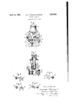
- Fig.. l is a perspective view of a double actin push utton master switch embodying t e improvements of the present invention
- Fig. 2 1 s a sectional view revealing more clearly the arrangement for the bridging contact and igs. 3, 4, 5 and 6 show diagrammatically the relative positions of the bridging contact as it wipes into engagement with the upper and lower pairs of stationary contacts.
- the double acting push button switch comprises a base or frame 10, preferably formed of moulded insulating material with an open slot 11 located in one side thereof.
- the pair of stationary contacts 12 are mounted on the block in spaced a art relation at one side of the slot 11, pre erably being held in position by rivets anchored in the holes 13 formed in the base 1.0.
- the block 10 is suitably formed to provide easy access to the terminal screws 14 by means of which the circuit conductors are connected to the stationary contacts 12.
- a second pair of a stationary contacts 15 are mounted on the block 10 on the opposite side of the slot 11, also preferably by means of rivets 16.
- the upper portion 17 of tho block 10 preferably is cutaway t0 permit ready access to the terminal screws 18 provided for connecting the circuit terminals to the stationary switch Contact 15.
- the bridging contact member 20 is mounted for movement between the pairs of stationary contacts 12 and 15 on the opposite sides of slot 11. As more clearly shown in Fig. 2, the bridging contact is 'mounted on the reci rocating operating rod 21 which carries t e push button 22 at this upper end.
- the operating rod 21 preferably is of square or rectangular cross section and has a freely sliding non-rotatable fit with a suitable opening formed inthe u per portion 17 of the block 10.
- the reducedO section 23 at the lower end of the operating rod 21 is screw-threaded and carries the projecting collar or washer 24, which is held in position by the nut 25 and lock washer 26.
- the bridging contact 20 is provided with an cifcenter rocking pin 27, which preferably 1s formed by punching out the metal of the contact member as indicated in the drawing.
- the non-circular opening 28 in the bridging contact member is made somewhat larger than the cross section of the operating rod 21 extending therethrough so as to permit free tilting and rocking movement of the bridging contact member on the rocking pin 27 when the bridging member engages with thehstationary contacts cooperating therewit
- the bridging contact member 20 is provided with the skewed contact portions 30 and 3l which-project slightly upward and downward from the opposite edges of the bridging contact so as to engage respectively with the upper stationary contacts 12 and the lower stationary contacts 15. In order to yieldingly bias the bridging contact 20 to a position in laterally skewed loo Yoperating' rod 21 andthe bridging contact 20.
- the contact portions 30 at one ed e of the bridging contact'20 are equidistant the contact portions 31 at the opposite edge of the brid 'ng contact 20 also are equidistant from t e stationary contacts but are at a different distance than the contactportions 30.
- the biasing spring 34 is interposed between the.
- Tiie biasing spring 34 is somewhat stronger than the blasing spring 32 and hence serves to operate the bridging contact 2O to the tilted position in which it is shown in Fig. 2, thereby compressing the spring 32.
- the bridging contact 20 normally closes the circuit throu h the stationary contacts 12 and consequenty normally opens the circuit through the stationary contacts 15.
- the tilting and rocking motion imparted to the bridgingcontact 20 is as follows: As the operating vrod 21 is lowered, the biasing spring 32 serves to rock the bridging contact 20 on the rocking pin 27 until the portion of the bridging contact 20, on the opposite side of the operating arm 21 from the rocking pin 27, rests upon the shoulder 24. In this way, as shown in Fig.
- the skewed portions 30 of the bridging contact 20 are substantially simultaneously disengaged from the pair of spaced apart stationary contacts 12. Thereafter the bridging contact 2() is maintained on the operating rod 21 in skewed alignment with each pair of the stationary contacts. As the downward movement of the operating rod 21 is continued, the skewed portions 31 extending downward from the rear edge of thebridging contact 2O are brought substantially simultaneously into engagement with the lower pair of stationary contacts 15.
- the substantially simultaneous disengagement of the bridging contact 20 from thestationary contact 12 enables a simultaneous double break to be obtained which is most effective in interrupting the current in the circuit. Also the simultaneous double break distributes the arcing duty between the conrom the stationary contacts and tacts and thereby prevents localized burning or pitting of any particular contact.
- the biasing spring 34 Upon the release of the push button 22, the biasing spring 34 returns the bridging contact 20 to its initial position.
- the brid ing contact 20 sugstantially simultaneousIy disengages the lower pair of stationary contacts 15 returns to its position in skewed alignment with the stationary contacts so that the skewed projecting portions 30 substantially simultaneously engage the upper discourse. ⁇ of stationary contacts 12.
- the further upward movement of the operating rod 21 serves ⁇ to tilt the bridging contact 20 about the rocking pin 27 and in this way produce a wiping, rolling action of the skewed portions 30 on the statlonary contacts 12 as illustrated in Figs. 3 and 4.
- the projecting boss 37 is formed to be received into a suitable opening in the member upon which the switch is mounted.
- the improved double acting switch embodying the present invention is not only of compact, rugged, and inexpensive construction, permitting ease of mounting and wiring, but also effectively insures self-cleaning, wiping action between the contacts so as always to obtain good contact engagement therebetween.
- a switch comprising a pair of spaced apart stationary contacts, a bridging contact therefor, amovable operating member for the bridging contact, and means for tiltably mounting the bridging contact on the operating member in skewed alignment with the stationary contacts to effect substantially sil'IE multaneous engagement and disengagement therewith with a wiping action.
- a switch comprising a pair of spaced apart stationary contacts, a bridging contact therefora movable operating member for the bridging contact, and means including a rocking pin for tiltably mounting the bridging contact on the operating member in skewed alignment with the stationary contacts to effect a wiping action upon engagement therebetween.
- a switch comprising a pair of spaced apart contact plates, a bridging contact therefor having skewed projecting portions at the edge thereof for engaging with said stationary contact plates, a movable operating member having the bridging contact tiltably mounted thereon, and means for biasing the bridging contact to a position in laterally skewed alinement with the spaced apart contact plates for effecting substantially simultaneous disengagement and engagement of the skewed projecting portions .of the bridging contact with the stationary contact plates with a wiping action.
- a switch comprising a pair of spaced apart stationary contact plates, a bridging contact having skewed projecting portions at one edge thereof for engaging with said stationary plates, a movable operating member for the bridging contact, and means including a rocking pin for tiltably mounting the bridging contact on the operating member in laterally skewed alignment with the stationary contact plates to effect a wiping action upon engagement therebetween.
- a double acting switch comprising two pairs of stationary spaced apart contacts mounted in opposing alignment, a movable bridging contact having oppositely skewed projecting portions at the opposite edges thereof for engaging with the stationary contacts, and an operating member extending between the opposing airs of stationary contacts and having the ridging member tiltably mounted thereon.
- a double acting switch comprising two pairs of stationary spaced apart contacts mounted in opposin contact havin oppositely skewed projecting portions at te opposite edges thereof for engaging with the stationary contacts a movable operating member for the bridging contact, and means including a rocking pin for tiltably mountin the bridging contact on the operating mem er in laterally skewed alignment with each pair of the stationary contacts to eect a wiping action upon enga ement therebetween.
Landscapes
- Push-Button Switches (AREA)
Description
April 2, 1932. G. H. DoRGl-:LOH ET AL.
ELECTRIC SWITCH Filed March 1'5, 1930 details of the mountiig Patented Apr. l2, 1932 UNITED -STATES PATENT OFFICE GEORGE E. DORGELOH, OIPEAST ORANGE, THOMAS I. MASLIN, F BLOOMIIELD, NEW JERSEY, ASSIGNORS TO GENERAL ELECTRIC COMPANY, A CORPORATION 0F NEW YORK ELECTRIC SWITCH Application led Iarch 15, 1980. Serial No. 433,195.
Our invention relates to electric switches and more particularly to ush button master switches and has for its o ject the provision of an improved form of switch of small overall size but of ample current carrying and interrupting capaclty in which speclal provision is made for insuring a rolling and wipin action between the switch contacts in or er to obtain self-cleaning operation. Our improved form of switch also provides for ease of mounting and wiring and involves onl a relatively few parts of simple, rugged an inexpensive construction.
While not necessarily limited thereto, the
improvements of the present invention are particularly adapted for use in a double acting push button, master switch for controlling both normally open and normally closed circuits. In carrying the invention into effeet in such a switch, a single bridging contact member is employed for roviding a double break in both the normal y open and normally closed circuits and is so mounted on a special off-center rocking pin associated with the push button operating rod that the rolling and wipin action of the bridging member is obtaine upon engagement thereof with each of two pairs of stationary contacts mounted in opposing spaced alignment.
In the accompanying drawings Fig.. l is a perspective view of a double actin push utton master switch embodying t e improvements of the present invention; Fig. 2 1s a sectional view revealing more clearly the arrangement for the bridging contact and igs. 3, 4, 5 and 6 show diagrammatically the relative positions of the bridging contact as it wipes into engagement with the upper and lower pairs of stationary contacts.
In the preferred form shown in Fig. 1 the double acting push button switch comprises a base or frame 10, preferably formed of moulded insulating material with an open slot 11 located in one side thereof. The pair of stationary contacts 12 are mounted on the block in spaced a art relation at one side of the slot 11, pre erably being held in position by rivets anchored in the holes 13 formed in the base 1.0. The block 10 is suitably formed to provide easy access to the terminal screws 14 by means of which the circuit conductors are connected to the stationary contacts 12.
A second pair of a stationary contacts 15 are mounted on the block 10 on the opposite side of the slot 11, also preferably by means of rivets 16. The upper portion 17 of tho block 10 preferably is cutaway t0 permit ready access to the terminal screws 18 provided for connecting the circuit terminals to the stationary switch Contact 15.
The bridging contact member 20 is mounted for movement between the pairs of stationary contacts 12 and 15 on the opposite sides of slot 11. As more clearly shown in Fig. 2, the bridging contact is 'mounted on the reci rocating operating rod 21 which carries t e push button 22 at this upper end. The operating rod 21 preferably is of square or rectangular cross section and has a freely sliding non-rotatable fit with a suitable opening formed inthe u per portion 17 of the block 10. The reducedO section 23 at the lower end of the operating rod 21 is screw-threaded and carries the projecting collar or washer 24, which is held in position by the nut 25 and lock washer 26. It will be observed that the bridging contact 20 is provided with an cifcenter rocking pin 27, which preferably 1s formed by punching out the metal of the contact member as indicated in the drawing. The non-circular opening 28 in the bridging contact member is made somewhat larger than the cross section of the operating rod 21 extending therethrough so as to permit free tilting and rocking movement of the bridging contact member on the rocking pin 27 when the bridging member engages with thehstationary contacts cooperating therewit It will be noted that the bridging contact member 20 is provided with the skewed contact portions 30 and 3l which-project slightly upward and downward from the opposite edges of the bridging contact so as to engage respectively with the upper stationary contacts 12 and the lower stationary contacts 15. In order to yieldingly bias the bridging contact 20 to a position in laterally skewed loo Yoperating' rod 21 andthe bridging contact 20.
With the bridging contact 20 thus biased to a position in laterally skewed alinement with Y 'the stationary contacts, the contact portions 30 at one ed e of the bridging contact'20 are equidistant the contact portions 31 at the opposite edge of the brid 'ng contact 20 also are equidistant from t e stationary contacts but are at a different distance than the contactportions 30. In other words, pboth contact portions 30 and 31 are in alinement with the stationary contacts but the two portions 30 and 31 are laterally skewed with respect to the stationary contacts. Likewise in order to bias the bridging contact into engagementwith the upper pair of stationary contacts 12 and out of engagement with the lower pair of contacts 15, the biasing spring 34 is interposed between the. ush button 22 and the top of the block 10. Tiie biasing spring 34 is somewhat stronger than the blasing spring 32 and hence serves to operate the bridging contact 2O to the tilted position in which it is shown in Fig. 2, thereby compressing the spring 32.
With the switch thus constructed, the bridging contact 20 normally closes the circuit throu h the stationary contacts 12 and consequenty normally opens the circuit through the stationary contacts 15. Upon operation of the push button 22 to disengage the bridging contact 20 from the stationary contacts 12 and operate the same into engagement with the stationary contacts 15, the tilting and rocking motion imparted to the bridgingcontact 20 is as follows: As the operating vrod 21 is lowered, the biasing spring 32 serves to rock the bridging contact 20 on the rocking pin 27 until the portion of the bridging contact 20, on the opposite side of the operating arm 21 from the rocking pin 27, rests upon the shoulder 24. In this way, as shown in Fig. 3, the skewed portions 30 of the bridging contact 20 are substantially simultaneously disengaged from the pair of spaced apart stationary contacts 12. Thereafter the bridging contact 2() is maintained on the operating rod 21 in skewed alignment with each pair of the stationary contacts. As the downward movement of the operating rod 21 is continued, the skewed portions 31 extending downward from the rear edge of thebridging contact 2O are brought substantially simultaneously into engagement with the lower pair of stationary contacts 15. The substantially simultaneous disengagement of the bridging contact 20 from thestationary contact 12 enables a simultaneous double break to be obtained which is most effective in interrupting the current in the circuit. Also the simultaneous double break distributes the arcing duty between the conrom the stationary contacts and tacts and thereby prevents localized burning or pitting of any particular contact. Moreover, due tothe rocking action of the bridging contact 20, any burning or pitting of the `jecting portions 31 to wipe and roll on the stationary contacts 15 thereby cleaning away any dirt, dust or other impediment that might prevent Good electrical conductin contact between tie bridging contact 20 and the stationary contacts. This wiping action thus maintains the contacts in a clean condition.
Upon the release of the push button 22, the biasing spring 34 returns the bridging contact 20 to its initial position. Durin this operation, the brid ing contact 20 sugstantially simultaneousIy disengages the lower pair of stationary contacts 15 returns to its position in skewed alignment with the stationary contacts so that the skewed projecting portions 30 substantially simultaneously engage the upper paix.` of stationary contacts 12. The further upward movement of the operating rod 21 serves` to tilt the bridging contact 20 about the rocking pin 27 and in this way produce a wiping, rolling action of the skewed portions 30 on the statlonary contacts 12 as illustrated in Figs. 3 and 4.
Provision is made for readily mounting the switch by roviding the recess hole 36 in the block 10 or receiving a holding down screw or bolt. In order to prevent turning of the block 10 about'the holding down screw or bolt, the projecting boss 37 is formed to be received into a suitable opening in the member upon which the switch is mounted.
From the foregoing it will be seen that the improved double acting switch embodying the present invention is not only of compact, rugged, and inexpensive construction, permitting ease of mounting and wiring, but also effectively insures self-cleaning, wiping action between the contacts so as always to obtain good contact engagement therebetween.
What we claim as new and desire to secure by Letters Patent of the United States, is,
1. A switch comprising a pair of spaced apart stationary contacts, a bridging contact therefor, amovable operating member for the bridging contact, and means for tiltably mounting the bridging contact on the operating member in skewed alignment with the stationary contacts to effect substantially sil'IE multaneous engagement and disengagement therewith with a wiping action.
2. A switch comprising a pair of spaced apart stationary contacts, a bridging contact therefora movable operating member for the bridging contact, and means including a rocking pin for tiltably mounting the bridging contact on the operating member in skewed alignment with the stationary contacts to effect a wiping action upon engagement therebetween.
3. A switch comprising a pair of spaced apart contact plates, a bridging contact therefor having skewed projecting portions at the edge thereof for engaging with said stationary contact plates, a movable operating member having the bridging contact tiltably mounted thereon, and means for biasing the bridging contact to a position in laterally skewed alinement with the spaced apart contact plates for effecting substantially simultaneous disengagement and engagement of the skewed projecting portions .of the bridging contact with the stationary contact plates with a wiping action.
4. A switch comprising a pair of spaced apart stationary contact plates, a bridging contact having skewed projecting portions at one edge thereof for engaging with said stationary plates, a movable operating member for the bridging contact, and means including a rocking pin for tiltably mounting the bridging contact on the operating member in laterally skewed alignment with the stationary contact plates to effect a wiping action upon engagement therebetween.
5. A double acting switch comprising two pairs of stationary spaced apart contacts mounted in opposing alignment, a movable bridging contact having oppositely skewed projecting portions at the opposite edges thereof for engaging with the stationary contacts, and an operating member extending between the opposing airs of stationary contacts and having the ridging member tiltably mounted thereon.
6. A double acting switch comprising two pairs of stationary spaced apart contacts mounted in opposin contact havin oppositely skewed projecting portions at te opposite edges thereof for engaging with the stationary contacts a movable operating member for the bridging contact, and means including a rocking pin for tiltably mountin the bridging contact on the operating mem er in laterally skewed alignment with each pair of the stationary contacts to eect a wiping action upon enga ement therebetween.
n witness whereof, we have hereunto set our hands this 13th dav of March, 1930. GEORGE H. DORGELOH. THOMAS I. MASLIN.
relation, a bridging
Priority Applications (2)
| Application Number | Priority Date | Filing Date | Title |
|---|---|---|---|
| US436195A US1853964A (en) | 1930-03-15 | 1930-03-15 | Electric switch |
| DEA61164D DE580085C (en) | 1930-03-15 | 1931-03-17 | Push button switch |
Applications Claiming Priority (1)
| Application Number | Priority Date | Filing Date | Title |
|---|---|---|---|
| US436195A US1853964A (en) | 1930-03-15 | 1930-03-15 | Electric switch |
Publications (1)
| Publication Number | Publication Date |
|---|---|
| US1853964A true US1853964A (en) | 1932-04-12 |
Family
ID=23731496
Family Applications (1)
| Application Number | Title | Priority Date | Filing Date |
|---|---|---|---|
| US436195A Expired - Lifetime US1853964A (en) | 1930-03-15 | 1930-03-15 | Electric switch |
Country Status (2)
| Country | Link |
|---|---|
| US (1) | US1853964A (en) |
| DE (1) | DE580085C (en) |
Cited By (11)
| Publication number | Priority date | Publication date | Assignee | Title |
|---|---|---|---|---|
| US2758169A (en) * | 1954-03-15 | 1956-08-07 | Gen Motors Corp | Electrical switch |
| US2811615A (en) * | 1954-10-29 | 1957-10-29 | Gen Electric | Double throw switch |
| US2859312A (en) * | 1956-03-15 | 1958-11-04 | Wilcolator Co | Electric switch mechanism |
| US2885516A (en) * | 1956-08-13 | 1959-05-05 | Square D Co | Contact holder |
| US2919327A (en) * | 1957-05-20 | 1959-12-29 | Allen Bradley Co | Contact structure for electromagnetic actuator |
| US2947827A (en) * | 1957-11-29 | 1960-08-02 | Clark Controller Co | Cam-operable twin-switches |
| US2954447A (en) * | 1958-12-18 | 1960-09-27 | Therm O Disc Inc | Thermostatic switch |
| US3099728A (en) * | 1958-06-11 | 1963-07-30 | Ward Leonard Electric Co | Electrical multipole control relays |
| US3273365A (en) * | 1963-05-14 | 1966-09-20 | Cincinnati Shaper Co | Method and apparatus for forming metal |
| US5359163A (en) * | 1993-04-28 | 1994-10-25 | Eaton Corporation | Pushbutton switch with adjustable pretravel |
| FR2868874A1 (en) * | 2004-04-09 | 2005-10-14 | Itt Mfg Enterprises Inc | ELECTRICAL SWITCH OF NORMALLY CLOSED TYPE |
Families Citing this family (3)
| Publication number | Priority date | Publication date | Assignee | Title |
|---|---|---|---|---|
| DE1003318B (en) * | 1955-04-23 | 1957-02-28 | Maecker Elan Schaltelemente | Push switch |
| DE1118312B (en) * | 1959-06-24 | 1961-11-30 | Bbc Brown Boveri & Cie | Low voltage switchgear |
| DE1615564B1 (en) * | 1967-01-17 | 1971-03-04 | Anker Werke Ag | Electrical switch for calculating, accounting and similar machines |
-
1930
- 1930-03-15 US US436195A patent/US1853964A/en not_active Expired - Lifetime
-
1931
- 1931-03-17 DE DEA61164D patent/DE580085C/en not_active Expired
Cited By (12)
| Publication number | Priority date | Publication date | Assignee | Title |
|---|---|---|---|---|
| US2758169A (en) * | 1954-03-15 | 1956-08-07 | Gen Motors Corp | Electrical switch |
| US2811615A (en) * | 1954-10-29 | 1957-10-29 | Gen Electric | Double throw switch |
| US2859312A (en) * | 1956-03-15 | 1958-11-04 | Wilcolator Co | Electric switch mechanism |
| US2885516A (en) * | 1956-08-13 | 1959-05-05 | Square D Co | Contact holder |
| US2919327A (en) * | 1957-05-20 | 1959-12-29 | Allen Bradley Co | Contact structure for electromagnetic actuator |
| US2947827A (en) * | 1957-11-29 | 1960-08-02 | Clark Controller Co | Cam-operable twin-switches |
| US3099728A (en) * | 1958-06-11 | 1963-07-30 | Ward Leonard Electric Co | Electrical multipole control relays |
| US2954447A (en) * | 1958-12-18 | 1960-09-27 | Therm O Disc Inc | Thermostatic switch |
| US3273365A (en) * | 1963-05-14 | 1966-09-20 | Cincinnati Shaper Co | Method and apparatus for forming metal |
| US5359163A (en) * | 1993-04-28 | 1994-10-25 | Eaton Corporation | Pushbutton switch with adjustable pretravel |
| FR2868874A1 (en) * | 2004-04-09 | 2005-10-14 | Itt Mfg Enterprises Inc | ELECTRICAL SWITCH OF NORMALLY CLOSED TYPE |
| WO2005098883A1 (en) * | 2004-04-09 | 2005-10-20 | Itt Manufacturing Enterprises, Inc. | Electrical switch of the normally closed type |
Also Published As
| Publication number | Publication date |
|---|---|
| DE580085C (en) | 1933-07-05 |
Similar Documents
| Publication | Publication Date | Title |
|---|---|---|
| US1853964A (en) | Electric switch | |
| US1978246A (en) | Electric circuit breaker | |
| US3852557A (en) | Electric switch with pivoting and wiping movable contractor | |
| US2384412A (en) | Electric switch | |
| US3337703A (en) | Snap switch with movable contacts on biased rocking plate | |
| US2472333A (en) | Snap acting electric switch | |
| US3200227A (en) | Carrier frame for movable contact and combination thereof with snap acting switch | |
| US1971212A (en) | Electric snap switch | |
| US4471181A (en) | Electric switch with cleaning action | |
| US2647974A (en) | Electric switch contact assembly | |
| US1600127A (en) | Push switch | |
| US2458511A (en) | Combined switch stud and fuse clip | |
| US1198340A (en) | Electric contact-making device. | |
| US3230334A (en) | Wiping action switch contacts | |
| US1963418A (en) | Arc suppressing air-break switch | |
| US2343807A (en) | Electric switch | |
| US3312801A (en) | Tool handle switch | |
| US2230737A (en) | Electric switch | |
| US1914529A (en) | Switch | |
| US3405243A (en) | Actuating lever for a switch | |
| US2418005A (en) | Electric switch | |
| US2174237A (en) | Electric switch | |
| US2210037A (en) | Electric switch | |
| US2188780A (en) | Snap switch | |
| US2549794A (en) | Control switch |