US1853961A - Needling apparatus - Google Patents
Needling apparatus Download PDFInfo
- Publication number
- US1853961A US1853961A US413695A US41369529A US1853961A US 1853961 A US1853961 A US 1853961A US 413695 A US413695 A US 413695A US 41369529 A US41369529 A US 41369529A US 1853961 A US1853961 A US 1853961A
- Authority
- US
- United States
- Prior art keywords
- shafts
- guides
- tracks
- frame
- carried
- Prior art date
- Legal status (The legal status is an assumption and is not a legal conclusion. Google has not performed a legal analysis and makes no representation as to the accuracy of the status listed.)
- Expired - Lifetime
Links
- 239000004744 fabric Substances 0.000 description 16
- 239000000463 material Substances 0.000 description 8
- 210000003414 extremity Anatomy 0.000 description 3
- 210000003141 lower extremity Anatomy 0.000 description 3
- 238000004519 manufacturing process Methods 0.000 description 3
- 238000010276 construction Methods 0.000 description 2
- 230000003534 oscillatory effect Effects 0.000 description 2
- 210000001364 upper extremity Anatomy 0.000 description 2
- 229920000742 Cotton Polymers 0.000 description 1
- 239000000969 carrier Substances 0.000 description 1
- 230000000994 depressogenic effect Effects 0.000 description 1
- 230000003028 elevating effect Effects 0.000 description 1
- 230000001788 irregular Effects 0.000 description 1
- 230000010355 oscillation Effects 0.000 description 1
- 230000002250 progressing effect Effects 0.000 description 1
- 210000002268 wool Anatomy 0.000 description 1
Images
Classifications
-
- D—TEXTILES; PAPER
- D04—BRAIDING; LACE-MAKING; KNITTING; TRIMMINGS; NON-WOVEN FABRICS
- D04H—MAKING TEXTILE FABRICS, e.g. FROM FIBRES OR FILAMENTARY MATERIAL; FABRICS MADE BY SUCH PROCESSES OR APPARATUS, e.g. FELTS, NON-WOVEN FABRICS; COTTON-WOOL; WADDING ; NON-WOVEN FABRICS FROM STAPLE FIBRES, FILAMENTS OR YARNS, BONDED WITH AT LEAST ONE WEB-LIKE MATERIAL DURING THEIR CONSOLIDATION
- D04H18/00—Needling machines
- D04H18/02—Needling machines with needles
-
- D—TEXTILES; PAPER
- D04—BRAIDING; LACE-MAKING; KNITTING; TRIMMINGS; NON-WOVEN FABRICS
- D04H—MAKING TEXTILE FABRICS, e.g. FROM FIBRES OR FILAMENTARY MATERIAL; FABRICS MADE BY SUCH PROCESSES OR APPARATUS, e.g. FELTS, NON-WOVEN FABRICS; COTTON-WOOL; WADDING ; NON-WOVEN FABRICS FROM STAPLE FIBRES, FILAMENTS OR YARNS, BONDED WITH AT LEAST ONE WEB-LIKE MATERIAL DURING THEIR CONSOLIDATION
- D04H18/00—Needling machines
Definitions
- the present inventio-n relates to apparatus for manufacturing fabric and embodies, more specifically, an improved device, commonly called a needlmg machine, ⁇ for Working suitcharacteristic.
- VMore particularly the invention concerns itself With a machine for "producing a nap,i
- An obj ectV of 4the invention accordingly, is to provide an apparatus of the above .character Which applies a suitable finish -to a fabric base, ⁇ the .operation progressing continuously and effectively with a minimum amount Iof 'manualfsupervlision
- a further ⁇ objectoffthe invention is to .pro-
- Figure 2 is a vievv from the left in Figure d, and :showing Vthe device .of Figure l.
- Figure :3 is a view ,1n section, takenyon 3.-.3 lof Figure 1, ⁇ and looking in the direction of the arrows.;
- Figuret is .a lvievv inseetion, taken on liner et+-4 kof Figure 3K, andlookingin the direction ofthe arrows.
- v Figure .5 isa view insection, taken Lon liney ,r
- a horizontal shaft/f?)v7 is journaledin the closureinembers bt V of the ,standards and .extends across the in end elevation, taken machine Iunder the :bed yplate Zat.
- Suitable apertuinesb8 are @formed ainrthe adjacentsides of the standards 3b tofreceivethe longitudinal shaft :'57, manually .operable wheels @b9 :being secured ,tothe-.ends o-f shaft-,1:67 @to enablethe mechanmn tothe' elevated asdes-ired.
- a split section 512 is preferably formed at the top of the standards and ⁇ operated by a manual crank Z213 in a well known manner to lock the sleeves b2 in a desired position.
- Heads o are secured to the upper ends of sleeves b2 and provide journals c within which pivot shafts 03 are mounted.Y These pivot shafts are secured to the opposite ends of a head Z which preferably carries the needling mechanism as hereinafter described.
- Vertically extending brackets d are formed upon the head d and spaced at suitable intervalsto afford bearings for a crank shaft e, such bearings preferably being spaced in pairs as clearly shown in Figure l. Between each pair of brackets d', eccentrics e are mounted upon shaft e. 'Ihe throws of the respective eccentrics of each pair are preferably 180 apart, thus causing the ⁇ ⁇ crank arm of one eccentric of each pair to be diamerically opposite to the crank arm of the other eccentric of each pair. This relationship is clearly shown in Figure 6.
- Brackets 04 are mounted upon the pivot shafts 03 and receive the ends of crank shaft e, a pulley e2 being mounted at one end of the crank shaft to be driven by a driving pulley e3, the axis of which preferably coincides with the axis of the pivot shafts 03. Power from any suitable source may be supplied to A the driving pulley e3 and thus supply the necessary motive power to crank shaft e.
- guide tracks f2 which may be positioned with respect to the guides by means of bolts f3.
- Spaced vertical recesses or grooves f4 are formed in the guides f and receive oscillating shafts g, described more fully hereinafter.
- Guide tracks f2 are formed with grooves f5 which cooperate with keys g upon shafts g to transmit the oscillatory motion of shafts g to the tracks f2.
- two reciprocating tool heads 7L are utilized.
- the heads are similar in construction and formed with spaced lateral sides 7L which are recessed at h2 and upon which guide plates h3 are secured by means of bolts h4.
- the plates h3 vare recessed at 71,5 to receive the projecting rib of the guide shoes f2, thus transmitting the oscillating movement of the shafts g to the movable heads h.
- Jaws 71.6 are formed on the lower extremities of the heads 7L and receive tool carriers k7 which may be provided with a plurality of needles LS, the needles of the respective heads being preferably staggered in order that their work upon the fabric base may be uniformly distributed over thearea of the latter.
- crank shaft e Adjacent the extremities of crank shaft e, collars j are mounted. 'Ihe'se collars are formed with cam tracks y" and rotate with the crank shaft.
- Shafts g are connected to extending shaft sections g2 which are journaled in suitable extensions d2 and of, formed upon the head d.
- Extension cl3 is shorter than the extension cl2 and its shaft section g2 i is correspondingly shorter.
- crank arms g3 Mounted upon the upper extremities of the shaft sectionsl g2 are crank arms g3 having fingers g4 provided with rollers g5.
- the arms g3 for the respective shafts g2 are similar in construction but spaced upon opposite sides of the collars j, the rollers g5 engaging the cam groove y" as will be readily seen from Figures l, 3, and 4L.
- the rotation of shaft e is transmitted to the shafts g in the form Vof oscillatory motion, this motion being imparted to the movable heads 7L to cause the latter to be advanced and retracted periodically in a plane perpendicular to the vertical longitudinal plane of the machine.
- This Vmotion causes the movableV heads to be advanced with the fabric base. upon which they work and thus enable the needles to engage the base as the latter moves.
- the bed plate a is formed with a horizontal table a within which slots a2 are formed. As the needles 71,8 are depressed to engage the fabric, they are received within the slots a2 and thus enjoy an unobstructed path of movement.
- shafts g may be taken, at the lower extremities thereof, by stub shafts gV which are preferably journaled ⁇ in the lower extremity of the respective guides Suitable adjusting mechanism l(/7 may be provided and the guides may be held in opera-' tive position by means of brackets Z914 which are secured to the standards b. Lock pins Z215 are carried by the brackets 614 and engage the guides to lock them in the desired position.
- crank shaft e With power being suplied to the driving pulley e3, crank shaft e rotates to reciprocate the heads 7L in vertical planes. Simultaneously with their vertical reciprocation the oscillation of shafts g, derived through cam .groove y" and associated connections, is
- asuitable fabric has been'indicated at Z, in dotted lines and passes'under ⁇ the belt lo.
- Cotton, wool fibres, or any other suitable material may be distributed upon the base as it passes under the belt and thus car ried under the descending needles ofthe respective heads L.
- the needles As the needles pass through the fabric base they drive such material therethrough and cause it to be lodged in the base, the withdrawal of the needles leaving such material lodged therein.
- the material may be so effectively lodged in the base at a multiplicity of points that the nished product resembles the soft and irregular surface of any desired mate# rial.
- the particular material used in connection with the base may be varied as desired to simulate any desired fabric and in view of the fact that the needles advance with the base, the productivity of the machine is very great.
- Vthe heads fromthe material on.. the tables' fromlffollowing-.the needles in their'upward strokes', ⁇ 1 2.
- a deviceof the ⁇ charactes-describedl comprising a' frame, a work table on the' frame, vertical. vguideslcarried by the frame, a plug.-y
- a device of the characterl described comprising a frame, a work table o-n the frame, ⁇
- eachv guide Aand having means to reciprocate the'heads from thev crankshaft, cam grooves spaced at either end ,of the-crank shaft, and ycamf followers carried by thev respective first shafts yand engaging the respective grooves on opposite.
- -A device of the character described conij g if prising a frame, a work table on the frame, vertical guides carried by the frame, a plurality ofguide tracks carried by each guide,
- a device of the character described comprising a frame, a Work table on the frame7 vertical guides carried by the frame, guide tracks carried by the guides, shafts mounted in the guides and having portions engaging the tracks, a needle carrying head slidably v mounted on the tracks, a crank shaft carried by the guides, means connecting the crank shaft with the head to oscillate the latter, cam grooves on the crank shaft, means on the ⁇ first shafts engaging the grooves to oscillate the said shafts, and means to mount the guides pivotally.
- a device of the character described comprising a frame, a Work table on theV frame, v
- a device of the character described comprising a frame, a Work table on the frame, vertical guides carried by the frame, guide tracks carried by the guides, shafts mounted in the guides and having portionsengaging the tracks, a needle carryinghead slidably mounted on the tracks, and means to recprocate the head and oscillate the shafts.
- a device of the character described comprising a frame, a Work table on the frame, vertical guides carried by the frame, guide tracks carried by the guides, shafts mounted in the guides and having portions engaging the tracks, and means to oscillate the shafts.
- a device of the character described comprising a frame, a Work table on the frame, vertical guide tracks carried by the frame, a head slidably mounted between the guide tracks, means to move the h-ead vertically on the tracks, and means to move the tracks in a horizontal plane.
Landscapes
- Engineering & Computer Science (AREA)
- Textile Engineering (AREA)
- Treatment Of Fiber Materials (AREA)
Description
April l2, 1932.
A. CURIONI NEEDL I-NG- APPARATUS BYELL?, M
ELSy A ITORNE YS April l2, 1932. v AQ cuRloNl NEEDLING APPARATUS Filed new 15, 1929 s sheets-shetv2 A'VENTOR fw-7 M. G, W
121s ATTORNEYAV v April 12, 1932; A. cuRloNl NEEDLING APPARATUS Filed Dec. 13, 1929' 3 Sheets-Sheet 3 INVENTOR '010,
ELS ATTORNEYS Patented Apr. 12, 1932 Ampo -GURIONL 0F Leiten,
NT New YQRKAASSIGNOR tumori aros. me, 'a CORPORATION OF YEQRK 'Y l mamme Analist-UUS Y The present inventio-nrelates to apparatus for manufacturing fabric and embodies, more specifically, an improved device, commonly called a needlmg machine, `for Working suitcharacteristic.
VMore particularly the invention concerns itself With a machine for "producing a nap,i
or sur-face, upon a fabrictof simulate the ap 19Y pearance and characteristics of certain deisired materials. It is conternplated7 for exvolved Vdifficult and expensive operations Which have seriously retarded the commercial y productivity of the resulting fabric, thus causing the .costithereof 4to .approximate the cost of the goods simulated so closely as not to justify the marketing of Ythe imitating goods. Utilizing -the'sfundamental principle of applying a suitable finish to an inferior fabric, the present invention. carries the' manufacturing thereof forwardV to suchy anv extent that the resulting product `can abe manufactured inexpensively :and quickly,` thus ydrawing the `process involved into :thatv class of industry which requiresandOersan enormous and rapid output at a compara- 4 tively inexpensive figure yto justify quantity 40" production at .minimum overhead.v An obj ectV of 4the invention, accordingly, is to provide an apparatus of the above .character Which applies a suitable finish -to a fabric base, `the .operation progressing continuously and effectively with a minimum amount Iof 'manualfsupervlision A further {objectoffthe invention is to .pro-
videadevice ofthe .above charac-ter in which' the ifabric lease 4is Worked Jcontinuously and 50 rapidly, 'the operationethereof .iloeingncornV able fabric and causing it to have a desiredA *Ap'pncation mea v1`Jecember1: 1929. serieu No. 413,695;
trolled through mechanism `vvhielay is readvilfj7 constructed andfserviced. f
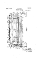
Further objects, not speclically .,eIluiIJe-l rated above, Wil-l be apparent .as the invention isdeSGribed lin greater .detail in connection With .the accompanying drawings, `wherein Figure f1 is a view in vfront elevation, part..-Y ly section, fand showing the .device con.- structedv in accordance lvvith the present vent-ion.
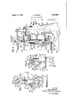
Figure 2 is a vievv from the left in Figure d, and :showing Vthe device .of Figure l.
Figure :3 is a view ,1n section, takenyon 3.-.3 lof Figure 1, `and looking in the direction of the arrows.; I
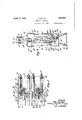
Figuret is .a lvievv inseetion, taken on liner et+-4 kof Figure 3K, andlookingin the direction ofthe arrows.
vFigure .5 isa view insection, taken Lon liney ,r
Y 5*-5of Figure, ,and looking in .the .direc-l ftion .of Jthe larrovvs. v Y
GTG of Figure '1, and, looking .in the l.direc-- tion .of the arrows.
lReferring to ythel .above dravvings,'k.a desigfY natos the `bed ,plate .or horizontal :Working table .of fa machine for :producing v.a desired fnishupon a .desired base in aceordance with the .present invention. #This ibed plate v.is
mountednp on supporting .bracketsfbfformed uponvertical end standards Y). lThese 'endV standards .aneprefena'blyhollow and slidaloly mount-.sleeves t? `Within Afthe flower extremities of which nutsjbV3 aresecu-red. `'illiesenuts` are` threadedto lreceive elevating .worm `,shafts b4., j ournaled inwardzlyextending brackets b5 which are formed .Jupon'iclosure' plateszt carried .by the standards J). A horizontal shaft/f?)v7 is journaledin the closureinembers bt V of the ,standards and .extends across the in end elevation, taken machine Iunder the :bed yplate Zat. @Suitable apertuinesb8 are @formed ainrthe adjacentsides of the standards 3b tofreceivethe longitudinal shaft :'57, manually .operable wheels @b9 :being secured ,tothe-.ends o-f shaft-,1:67 @to enablethe mechanmn tothe' elevated asdes-ired. Bevel pinions Z210 .are `mounted upon the .Sha-.H1157 and engage cooperatingwpiru'ons 191111 .upon the lovver'extremities .of the elevatingmorms b4. In this manner, it will be readily apparent that the sleeves b2 may be elevated or lowered simultaneously to a desired amount. A split section 512 is preferably formed at the top of the standards and` operated by a manual crank Z213 in a well known manner to lock the sleeves b2 in a desired position.
Heads o are secured to the upper ends of sleeves b2 and provide journals c within which pivot shafts 03 are mounted.Y These pivot shafts are secured to the opposite ends of a head Z which preferably carries the needling mechanism as hereinafter described. Vertically extending brackets d are formed upon the head d and spaced at suitable intervalsto afford bearings for a crank shaft e, such bearings preferably being spaced in pairs as clearly shown in Figure l. Between each pair of brackets d', eccentrics e are mounted upon shaft e. 'Ihe throws of the respective eccentrics of each pair are preferably 180 apart, thus causing the` `crank arm of one eccentric of each pair to be diamerically opposite to the crank arm of the other eccentric of each pair. This relationship is clearly shown in Figure 6.
Brackets 04 are mounted upon the pivot shafts 03 and receive the ends of crank shaft e, a pulley e2 being mounted at one end of the crank shaft to be driven by a driving pulley e3, the axis of which preferably coincides with the axis of the pivot shafts 03. Power from any suitable source may be supplied to A the driving pulley e3 and thus supply the necessary motive power to crank shaft e.
carry pairs of guide tracks f2 which may be positioned with respect to the guides by means of bolts f3. Spaced vertical recesses or grooves f4 are formed in the guides f and receive oscillating shafts g, described more fully hereinafter. Guide tracks f2 are formed with grooves f5 which cooperate with keys g upon shafts g to transmit the oscillatory motion of shafts g to the tracks f2.
In the form of mechanism in which the present invention has been embodied, two reciprocating tool heads 7L are utilized. The heads are similar in construction and formed with spaced lateral sides 7L which are recessed at h2 and upon which guide plates h3 are secured by means of bolts h4. The plates h3 vare recessed at 71,5 to receive the projecting rib of the guide shoes f2, thus transmitting the oscillating movement of the shafts g to the movable heads h. Jaws 71.6 are formed on the lower extremities of the heads 7L and receive tool carriers k7 which may be provided with a plurality of needles LS, the needles of the respective heads being preferably staggered in order that their work upon the fabric base may be uniformly distributed over thearea of the latter. v
Shoulders hg are forme-d on each movable head and receive bolts hm upon which yokeshaped bearings h are formed. Connecting rods z' are secured to the bearings 7b and mounted, at their upper extremities, over the respective eccentrics e by suitable eccentric straps 'i'. In this manner, the rotation of crank shaft e is transmitted t0 the heads L to impart reciprocating motion to the latter. Since the throws of the eccentrics are diametrically opposed, one head will be moved upwardly while the other is moving downwardly, thus alternately engaging the work as it passes over the work table or bench a.
Adjacent the extremities of crank shaft e, collars j are mounted. 'Ihe'se collars are formed with cam tracks y" and rotate with the crank shaft. Shafts g are connected to extending shaft sections g2 which are journaled in suitable extensions d2 and of, formed upon the head d. Extension cl3 is shorter than the extension cl2 and its shaft section g2 i is correspondingly shorter. Mounted upon the upper extremities of the shaft sectionsl g2 are crank arms g3 having fingers g4 provided with rollers g5. The arms g3 for the respective shafts g2 are similar in construction but spaced upon opposite sides of the collars j, the rollers g5 engaging the cam groove y" as will be readily seen from Figures l, 3, and 4L. By means of the above connection, therefore, it will be seen that the rotation of shaft e is transmitted to the shafts g in the form Vof oscillatory motion, this motion being imparted to the movable heads 7L to cause the latter to be advanced and retracted periodically in a plane perpendicular to the vertical longitudinal plane of the machine. This Vmotion causes the movableV heads to be advanced with the fabric base. upon which they work and thus enable the needles to engage the base as the latter moves. i
` The bed plate a is formed with a horizontal table a within which slots a2 are formed. As the needles 71,8 are depressed to engage the fabric, they are received within the slots a2 and thus enjoy an unobstructed path of movement.
The reaction of shafts g may be taken, at the lower extremities thereof, by stub shafts gV which are preferably journaled`in the lower extremity of the respective guides Suitable adjusting mechanism l(/7 may be provided and the guides may be held in opera-' tive position by means of brackets Z914 which are secured to the standards b. Lock pins Z215 are carried by the brackets 614 and engage the guides to lock them in the desired position.
In order that the fabric base may be held against the work table a to permit the ready withdrawal of the needles hs therefrom a guide belt k is provided. This belt is prefthe operation of the machine isas follows.l
With power being suplied to the driving pulley e3, crank shaft e rotates to reciprocate the heads 7L in vertical planes. Simultaneously with their vertical reciprocation the oscillation of shafts g, derived through cam .groove y" and associated connections, is
imparted to the movable heads to vcausevthe latter to be advanced and retracted in the direction of and counter to the direction of movement of the fabric base, respectively. As the heads h descend, needles hs are driven through the fabric base and moved therewith until the respective headsare moved upward-` vily during the opposite throw of their respective driving eccentrics which are rotating with shaft e. Upward movement of the heads and needles withdraws the latter from the fabric and permits them tobe advanced against the fabric and into the same at its initial starting position.Y 'y
In Figure 2, asuitable fabric has been'indicated at Z, in dotted lines and passes'under` the belt lo. Cotton, wool fibres, or any other suitable material may be distributed upon the base as it passes under the belt and thus car ried under the descending needles ofthe respective heads L. As the needles pass through the fabric base they drive such material therethrough and cause it to be lodged in the base, the withdrawal of the needles leaving such material lodged therein. By providing a, plurality of heads, each having a suitable number of needles disposed in staggered? relationship, the material may be so effectively lodged in the base at a multiplicity of points that the nished product resembles the soft and irregular surface of any desired mate# rial. It will be readily understood that the particular material used in connection with the base may be varied as desired to simulate any desired fabric and in view of the fact that the needles advance with the base, the productivity of the machine is very great.
While the invention has been described with specific reference to the accompanying rality of guide tracks carried by each guide,
shaftsv mounted in each Vguide and having portions engaging the respective tracks, a plurality of needle carrying heads slidably mountedY inspacedl tracks ofA the respective guides, ancrank shaft l'carried by the guides,
means to reciprocate Vthe heads fromthe material on.. the tables' fromlffollowing-.the needles in their'upward strokes',` 1 2. --A deviceof the `charactes-describedl comprising a' frame, a work table on the' frame, vertical. vguideslcarried by the frame, a plug.-y
shafts mounted in each guide and having perf tions engaging the respective tracks, a Vplurality of needle carrying heads slidably:
`rality of guidetracks carried by.- each guide, t.
soiv
mounted in spaced tracks of "the respective" guides, a crank shaft carriedl by the guides,
means to reciprocate the heads from the crank p shaft alternately, clearances in the work table: to lreceive the needles, means to oscillate the first shafts from'the crank shaft, and meansto prevent material on the table from the vfol- 'lowingthe needles .in their Aupward strokes; p
' 3. `A. device ofthe character described com?" risin a frame a ywork table o-n the frame vertical guides carried by the frame, a'plu.
rality of guide tracks carried by each guide,
`shafts `mounted in'each guide and having portions engaging-the respective tracks, a
plurality of `needle carrying heads slidablyy mounted in spacedtracks o'fthe respective guides, a crank shaft carried by the guides,
means to recipro-cate the heads from the crank shaft alternately, clearances in thel work taioo ble to receive the needles, and means to oscil-v late the first shaft from the crank shaft.
' ll. A device of the characterl described comprising a frame, a work table o-n the frame,`
vertical guides carried by the frame, a plus rality of guide tracks carried by each guide,
'shafts mounted in eachv guide Aand having means to reciprocate the'heads from thev crankshaft, cam grooves spaced at either end ,of the-crank shaft, and ycamf followers carried by thev respective first shafts yand engaging the respective grooves on opposite. i
sides thereof.`
' 5. -A device of the character described conij g if prising a frame, a work table on the frame, vertical guides carried by the frame, a plurality ofguide tracks carried by each guide,
shafts mounted iii each guide andliavingportions engaging the respective tracks, a plurality of needle carrying heads slidably fromthecrank shaft. l o I f 6. A device Vof the character describedcommountedv in spacedv tracks of the respective ,1,25: guides, a crank shaftcarried by'theguides, means toreciprocate the vheads `from th'e'crank shaft, and means to oscillate theiirstf'shafts' prising a frame7 a Work table on the frame, Vertical guides carried by the frame, guide tracks carried by the guides, shafts mounted in the guides and having portions engaging the tracks a needle carrying head slidably mounted on the tracks, a crank shaft carried by the guides, means connecting the crank shaft With the head to oscillatethe latter, camgrooves on the crank shaft, means on the first shafts engaging the grooves to oscillate the said shafts, means to mount the guides pivotally, and means concentric to the mounting to transmit power to the crank shaft.
7 A device of the character described comprising a frame, a Work table on the frame7 vertical guides carried by the frame, guide tracks carried by the guides, shafts mounted in the guides and having portions engaging the tracks, a needle carrying head slidably v mounted on the tracks, a crank shaft carried by the guides, means connecting the crank shaft with the head to oscillate the latter, cam grooves on the crank shaft, means on the `first shafts engaging the grooves to oscillate the said shafts, and means to mount the guides pivotally.
8. A device of the character described comprising a frame, a Work table on theV frame, v
vertical guides carried by the frame, guide tracks carried by the guides, shafts mounted in the guides and having portions engaging the tracks, a needle carrying head slidably mounted on the tracks, a crank shaft carried by the guides, means connecting the crank shaft with the head to oscillate the latter, cam grooves on the crank shaft, and means on the first shafts engaging the grooves to oscillate the said shafts. y
9. A device of the character described comprising a frame, a Work table on the frame, vertical guides carried by the frame, guide tracks carried by the guides, shafts mounted in the guides and having portionsengaging the tracks, a needle carryinghead slidably mounted on the tracks, and means to recprocate the head and oscillate the shafts.
10. A device of the character described comprising a frame, a Work table on the frame, vertical guides carried by the frame, guide tracks carried by the guides, shafts mounted in the guides and having portions engaging the tracks, and means to oscillate the shafts.
11. A device of the character described comprising a frame, a Work table on the frame, vertical guide tracks carried by the frame, a head slidably mounted between the guide tracks, means to move the h-ead vertically on the tracks, and means to move the tracks in a horizontal plane.
This specification signed this 12th day of December, A. D. 1929.
ALDO CURIONI.
Priority Applications (1)
| Application Number | Priority Date | Filing Date | Title |
|---|---|---|---|
| US413695A US1853961A (en) | 1929-12-13 | 1929-12-13 | Needling apparatus |
Applications Claiming Priority (1)
| Application Number | Priority Date | Filing Date | Title |
|---|---|---|---|
| US413695A US1853961A (en) | 1929-12-13 | 1929-12-13 | Needling apparatus |
Publications (1)
| Publication Number | Publication Date |
|---|---|
| US1853961A true US1853961A (en) | 1932-04-12 |
Family
ID=23638247
Family Applications (1)
| Application Number | Title | Priority Date | Filing Date |
|---|---|---|---|
| US413695A Expired - Lifetime US1853961A (en) | 1929-12-13 | 1929-12-13 | Needling apparatus |
Country Status (1)
| Country | Link |
|---|---|
| US (1) | US1853961A (en) |
Cited By (1)
| Publication number | Priority date | Publication date | Assignee | Title |
|---|---|---|---|---|
| US5153970A (en) * | 1990-01-18 | 1992-10-13 | Textilmaschinenfabrik Dr. Ernst Fehrer Aktiengesellschaft | Mechanism for operating a needle board in a needling machine |
-
1929
- 1929-12-13 US US413695A patent/US1853961A/en not_active Expired - Lifetime
Cited By (1)
| Publication number | Priority date | Publication date | Assignee | Title |
|---|---|---|---|---|
| US5153970A (en) * | 1990-01-18 | 1992-10-13 | Textilmaschinenfabrik Dr. Ernst Fehrer Aktiengesellschaft | Mechanism for operating a needle board in a needling machine |
Similar Documents
| Publication | Publication Date | Title |
|---|---|---|
| CN201143644Y (en) | Multiple-array staggered form polisher | |
| US1853961A (en) | Needling apparatus | |
| CN203378639U (en) | Sole gluing component and automatic sole gluing machine with sole gluing component | |
| US1771117A (en) | Confection stringing or decorating machine | |
| CN105252637A (en) | Material distributing method for producing natural-marble-like polished tiles and material distributing machine of material distributing method | |
| US2834704A (en) | Method of producing bonded twistless yarn | |
| US1944112A (en) | Dough dividing and working machine | |
| CN111406120B (en) | Improved softening machine | |
| CN202262360U (en) | Wrapper block rotating device for croissant machine | |
| US1822509A (en) | Machine for making pile fabric | |
| CN108849636A (en) | A kind of duck's egg marking device | |
| US1753834A (en) | Machine for producing seamless bodies, sweetmeats, and others from plastic masses | |
| US1225365A (en) | Apparatus for perforating jacquard-cards. | |
| US2193916A (en) | Machine for ornamenting bricks | |
| CN221094524U (en) | Carbon black processing apparatus is used in chemical fiber production | |
| US98871A (en) | Frederick s | |
| CN103306084B (en) | Plush laser embossing machine | |
| US790920A (en) | Process of making candy. | |
| KR200270425Y1 (en) | patten machine for synthetic fiber | |
| US2724379A (en) | Automatic surfacing machine | |
| US1793842A (en) | Wood-slicing machine | |
| NL2033986B1 (en) | Textile fabric cutting machine | |
| US1024511A (en) | Pottery-machine. | |
| US1967464A (en) | Press | |
| CN221142271U (en) | A cutting device for fabric processing |