US1853959A - Vine and potato separator and potato buncher - Google Patents
Vine and potato separator and potato buncher Download PDFInfo
- Publication number
- US1853959A US1853959A US497451A US49745130A US1853959A US 1853959 A US1853959 A US 1853959A US 497451 A US497451 A US 497451A US 49745130 A US49745130 A US 49745130A US 1853959 A US1853959 A US 1853959A
- Authority
- US
- United States
- Prior art keywords
- potato
- potatoes
- closure
- hopper
- vine
- Prior art date
- Legal status (The legal status is an assumption and is not a legal conclusion. Google has not performed a legal analysis and makes no representation as to the accuracy of the status listed.)
- Expired - Lifetime
Links
- 235000002595 Solanum tuberosum Nutrition 0.000 title description 48
- 244000061456 Solanum tuberosum Species 0.000 title description 48
- 235000012015 potatoes Nutrition 0.000 description 26
- 239000007787 solid Substances 0.000 description 5
- 230000005484 gravity Effects 0.000 description 2
- NIXOWILDQLNWCW-UHFFFAOYSA-N Acrylic acid Chemical compound OC(=O)C=C NIXOWILDQLNWCW-UHFFFAOYSA-N 0.000 description 1
- 239000000463 material Substances 0.000 description 1
- 230000000284 resting effect Effects 0.000 description 1
Images
Classifications
-
- A—HUMAN NECESSITIES
- A01—AGRICULTURE; FORESTRY; ANIMAL HUSBANDRY; HUNTING; TRAPPING; FISHING
- A01D—HARVESTING; MOWING
- A01D33/00—Accessories for digging harvesters
- A01D33/10—Crop collecting devices, with or without weighing apparatus
Definitions
- My invention has for its object to provide an improved'vine and potato separator and a potato buncher for potato diggers, and, to
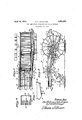
- Fig. 1 is a plan view of my improvements as applied to a potato digger with some parts broken away; 1 a
- Fig. 2 is a right side elevation of the parts shown in Fig. 1; Y
- Fig. 3 is a detall in vertical section show- .ing the lower end of the potato accumulator or hopper and the dropper attached thereto;
- Fig. 4 is a substantially horizontal section on the line 4 of Fig. 2.
- an ordinary standard potato digger includes a trunk or body portion 5 mounted in fan in clined position on the axle 6 of atwowheeled truck. At the forward'end ofthis trunk or body 5 is located a digging shovel not shown, in the drawings. In this trunk 5'is mounted aslat and link elevator 7 mounted on suitable sprockets, only the upper pair of which are shown in” the drawings and numbered 8. These sprockets 8 are carried by a common shaft, one end of which appearsin Fig. 2
- the saidelevator most of the dirt will be shaken outand dropped to the ground, but the potatoes and the vines will becarried upby the upper numerals 14 and 15, respectively, :14 denotend of which engageswith' thesprocket 17 on the right end of the shaft 15 that supfixed to the sidewalls of the trunk body 5a running fold of said elevator 7 and be delivered'over-the' upperend of'the same.
- the upper '7 5a ofthetrunk is mounted a second elevator j12of the slat and link type on suitable supportingfsprockets l3gfixed in pairs, respec-weoo tively, to two corresponding supporting shafts, the endsfoffwhich appear in Fig. 2 of thedrawings, and aremarked with the ingthe lower shaft','and 15' the upper shaft, 1.
- a cross rod19 Fixed in the trunk walls, and on this rod 19 are pivoted a series of arms 20 which extend clear to therear end of them'achine.
- An endless carrier 21 of the toothed slat'and chain type- is mounted on four sprockets 22,two of V which are fixed to the shaft 23, and the other two to the shaft 24.
- the shafts 23 and 24 aresuitably mounted in the sidebrackets 25 0 andextending rearward therefrom in a horizontal position.
- the shaft 24 extends, at one end, outward, beyond the adjacent bracket25 and is provided with a-sprocket26 engaged by a linkbelt chain 27, the forward vend of which is engaged by a sprocket 28 onthe shaft l5,rwhich'imparts motion to the second elevator 12.
- This endless carrier 21 is so located and mounted that it-travels in ahori 1 zontal plane and is so, positioned that its flee , potatoes and the vines from the delivery end of said elevator 12.
- the rods 20 overlie the upper running fold of the endless carrier 21, and the cross slats of this carrier are of such heights and the rods 20 are so located that the rearmost slats will raise the rear ends of the rods 20 and impart an up-and-.down.shaking ends secured to the brackets 25.
- the numeral 30 is a hopper-like receptacle having its up per end secured to the brackets 25, so that it is carried by said brackets with its forward edge slightly under-reaching the delivery end of the second elevator 12, and its open upper "end, or mouth, located directly below the receiving end of the endless carrier 21.
- This hopper 30 is provided with a dropper normally closed, but releasable at the will of the driver of the machine. As shown, this dropper is made up of a solid, or door-like piece 31,
- the said parts 31 and 32 afford a complete closure for the lower end of the hopper 30, so far as potatoes are concerned; and, when this closure is permitted to open, the potatoes, of course will drop out.
- This closure is controlled by the hereinbelow named connections.
- the numeral 35 represents a bell crank lever pivoted to one of the side walls of the hopper 30.
- the rear end of this bell crank lever 35 is connected by a link 36 to the solid part 31 of the hopper closure, at some distance away from the pivotal connection of the part 31 tothe hopper 30.
- the forward'arm of said bell crank 35 is connected by a rod 37 to a. foot lever 38 pivoted to an upstanding bracket arm 39 fixed to the trunk body 5, as clearly shown in Fig. 2 of the drawings.
- connection between the rod 37 and the lever 38 is a pivotal one.
- the location of the pivot for said lever 38 is higher than the pivot of the bell crank 35 and the throw of the lever 38 is of such extent that when the said lever is turned downward into its lowermost position, its outer end will stand below a straight line through the pivots of said two levers, or, in other words, be below the dead center and will, therefore, hold the closure of the hopper 30 in its closed position, as shown in Fig. 2 of the drawings; but when the lever 38 is thrown upward to its limit, then the said closure will drop by the gravity of its load of potatoes although this canbe assisted by the connections from the lever 38, and the accumulated bunch of potatoes willbe dropped onto the ground.
- the hopper being of a width to extend entirely across the machine.
- the upper'end of the hopper 30 is open thus affording a mouth extending entirely across the machine for the reception of the potatoes from the endless carrier 21.
- the rods 20 which overlie the carrier 21 are spaced sufliciently far apart notto interfere withthe free downward passage of the potatoes, but the said rods retain the vines.
- the slats on the endless carrier 21 are also so far apart that they do not interfere with the passage'of the potatoes into the mouth of the hopper.
- the operation of the machine as an entirety may besummarized as follows
- the potatoes, vines, and dirt, excavated by the shovel (not shown) of the digger are received on the primary elevator 7 and carried upward thereby, and, while this is being done,
- the potatoes and vines willbe deliveredtogether onto the rods'20 and the potatoes will fall through onto the carrier 21, while the vines will be held by the rods 20 and moved rearward by the teeth on the slats of said carrier 21 and be thrown 015: from the tail of the machine onto the ground.
- the potatoes drop down between the rods 20 and the slats of the machine, and then he will manipulate the lever 38 so as to throw it upward and rearwardbeyond its dead center and the closure of the hopper will immediately open under the weight of its bunchiot'potatoes supported thereby and drop to the ground, allowing the potatoes to drop out'in a bunch.
- a potatobuncher comprising a hopper adapted toreceive the potatoes from said separating elements and provided with a V closure upon which thepotatoes accumulate when the closure is in. its closed position but which v closure is releasable, at the will of the driver,
- the combination with a vine and potato separator comprising an endless carrier of the toothed slat and chain type, and aseries of pivoted rods overlying said carrier and receiving therefrom an up-and-down shaking hopper upon which the potatoes accumulate closure is in its open position and the ends digger, permits the potatoes to fall there'- through, and retains the vines on said rods 7 '95 I when the closure is in closed position and I 7 driver of the machine for dropping the bunches of potatoes to the ground.
Landscapes
- Life Sciences & Earth Sciences (AREA)
- Environmental Sciences (AREA)
- Harvesting Machines For Root Crops (AREA)
Description
April 12, 1932. B. o. CUDDIGAN VINE AND POTATO SEPARATOR AND POTATO BUNCHE'R Filed Nov. 22, 1930 Patented Apr. 12, 1932 UNITED! PATENT;
- massa- BARTHoLoMEw o. CUDDIG NQoF Anoiiemiimnsomn, nssrenonor own-Titian 'rofo, LB.
DIBBLE- AND ONE-THIRD-TO F, WQQHERMANN, BOTH oF ,REI) wins, MlNNES QTA vxnnAnn rornrro'sEr Aron'nnn POTATOBUNdHEB x Y 7 Application filed November 2 23930. Serial No: 497,451.
My invention has for its object to provide an improved'vine and potato separator and a potato buncher for potato diggers, and, to
this end my invention consists in the novel ,5 devices and combinations ofdevices hereinafter described and pointed out in they claims.
The accompanying drawingsillustrate my invention in its preferred form asappli'edto the delivery end of a potato digger; and in said drawings like notations referring to like parts throughout the several views,
Fig. 1 is a plan view of my improvements as applied to a potato digger with some parts broken away; 1 a
Fig. 2 is a right side elevation of the parts shown in Fig. 1; Y
; Fig. 3 is a detall in vertical section show- .ing the lower end of the potato accumulator or hopper and the dropper attached thereto; and
Fig. 4 is a substantially horizontal section on the line 4 of Fig. 2. y
As is well known, the delivery end of an ordinary standard potato digger includes a trunk or body portion 5 mounted in fan in clined position on the axle 6 of atwowheeled truck. At the forward'end ofthis trunk or body 5 is located a digging shovel not shown, in the drawings. In this trunk 5'is mounted aslat and link elevator 7 mounted on suitable sprockets, only the upper pair of which are shown in" the drawings and numbered 8. These sprockets 8 are carried by a common shaft, one end of which appearsin Fig. 2
of the drawings and ismarked with the numeral 9. One of the truck wheels, the'right hand member as shown, is provided'with a spur gearrlO which engages with the gear 11 on the end of the shaftQIand hence as the truck wheels revolve, motion will be im'e .parted to the sprocket 8 and these inturn will impart motion in the right directionto this slat and link elevator 7 The said elevator 7 receives, at its lower end, the vines;
the potatoes and most of the dirtexcavated by the shovel of the digger, and as these materials travel upwardwith. the saidelevator most of the dirt will be shaken outand dropped to the ground, but the potatoes and the vines will becarried upby the upper numerals 14 and 15, respectively, :14 denotend of which engageswith' thesprocket 17 on the right end of the shaft 15 that supfixed to the sidewalls of the trunk body 5a running fold of said elevator 7 and be delivered'over-the' upperend of'the same.
In the potato digger illustrated, the upper '7 5a ofthetrunk is mounted a second elevator j12of the slat and link type on suitable supportingfsprockets l3gfixed in pairs, respec-weoo tively, to two corresponding supporting shafts, the endsfoffwhich appear in Fig. 2 of thedrawings, and aremarked with the ingthe lower shaft','and 15' the upper shaft, 1.
which, through the sets of sprockets 13,'hithertonoted, impart traveling motion to the second elevator 12.1 This motion is secured through a link belt chain 16, the forward on the right end of the shaft 9to which are fixed the sprockets 8'that impart; motion to the main or primaryuelevatorj'Z. The rear end of said chain 16 engages a sprocket 18 i 5 ports the sprockets 13 that impart motion to the secondele'vator12. Some of the slats of said elevator 12 are teeth 12a. I g
Directly below the rear or upper'endof said shown as provided with second elevator '12 is located a cross rod19 :fixed in the trunk walls, and on this rod 19 are pivoted a series of arms 20 which extend clear to therear end of them'achine. An endless carrier 21 of the toothed slat'and chain type-is mounted on four sprockets 22,two of V which are fixed to the shaft 23, and the other two to the shaft 24. The shafts 23 and 24 aresuitably mounted in the sidebrackets 25 0 andextending rearward therefrom in a horizontal position. The shaft 24 extends, at one end, outward, beyond the adjacent bracket25 and is provided with a-sprocket26 engaged by a linkbelt chain 27, the forward vend of which is engaged by a sprocket 28 onthe shaft l5,rwhich'imparts motion to the second elevator 12. "This endless carrier 21 is so located and mounted that it-travels in ahori 1 zontal plane and is so, positioned that its flee , potatoes and the vines from the delivery end of said elevator 12. The rods 20 overlie the upper running fold of the endless carrier 21, and the cross slats of this carrier are of such heights and the rods 20 are so located that the rearmost slats will raise the rear ends of the rods 20 and impart an up-and-.down.shaking ends secured to the brackets 25. The numeral 30 is a hopper-like receptacle having its up per end secured to the brackets 25, so that it is carried by said brackets with its forward edge slightly under-reaching the delivery end of the second elevator 12, and its open upper "end, or mouth, located directly below the receiving end of the endless carrier 21. This hopper 30 is provided with a dropper normally closed, but releasable at the will of the driver of the machine. As shown, this dropper is made up of a solid, or door-like piece 31,
hinged to the forward wall of the lower end of the hopper 30, and of a series of spring fingers 32, all of which are separately hinged to the solid portions 31, forward of the edge of said door-like part 31 and bent upon them selves so that their rearward portions extend upwardly on an incline with their tips normally resting against the rear edge of the rear wall of the hopper 30. Headed and nutted bolts 33 pass through the solid portion 31 of the dropper and through holes in each of the spring fingers 32, and these bolts are subject to coiled springs 34 re-acting between the .nuts on the bolts and the underfaces of the spring fingers, and therefore, tending to hold the spring fingers in their closed position, as shown by the full lines in Figs. 2 and 3 of thedrawings. The said parts 31 and 32 afford a complete closure for the lower end of the hopper 30, so far as potatoes are concerned; and, when this closure is permitted to open, the potatoes, of course will drop out. This closure is controlled by the hereinbelow named connections. The numeral 35 represents a bell crank lever pivoted to one of the side walls of the hopper 30. The rear end of this bell crank lever 35 is connected by a link 36 to the solid part 31 of the hopper closure, at some distance away from the pivotal connection of the part 31 tothe hopper 30. The forward'arm of said bell crank 35 is connected by a rod 37 to a. foot lever 38 pivoted to an upstanding bracket arm 39 fixed to the trunk body 5, as clearly shown in Fig. 2 of the drawings. The connection between the rod 37 and the lever 38 is a pivotal one. The location of the pivot for said lever 38 is higher than the pivot of the bell crank 35 and the throw of the lever 38 is of such extent that when the said lever is turned downward into its lowermost position, its outer end will stand below a straight line through the pivots of said two levers, or, in other words, be below the dead center and will, therefore, hold the closure of the hopper 30 in its closed position, as shown in Fig. 2 of the drawings; but when the lever 38 is thrown upward to its limit, then the said closure will drop by the gravity of its load of potatoes although this canbe assisted by the connections from the lever 38, and the accumulated bunch of potatoes willbe dropped onto the ground.
As already noted, the side walls of the hopper 30 are rigidly secured to the brackets 25,
the hopper being of a width to extend entirely across the machine. The upper'end of the hopper 30 is open thus affording a mouth extending entirely across the machine for the reception of the potatoes from the endless carrier 21. The rods 20 which overlie the carrier 21 are spaced sufliciently far apart notto interfere withthe free downward passage of the potatoes, but the said rods retain the vines. The slats on the endless carrier 21 are also so far apart that they do not interfere with the passage'of the potatoes into the mouth of the hopper.
The operation of the machine as an entirety may besummarized as follows The potatoes, vines, and dirt, excavated by the shovel (not shown) of the digger are received on the primary elevator 7 and carried upward thereby, and, while this is being done,
'most of thedirt will drop through between the slats or cross rods of the elevator 7 to "the ground. The vines and thepotatoes will same, the rest of the dirt will be dropped out.
From the upper end of theelevator 12, the potatoes and vines willbe deliveredtogether onto the rods'20 and the potatoes will fall through onto the carrier 21, while the vines will be held by the rods 20 and moved rearward by the teeth on the slats of said carrier 21 and be thrown 015: from the tail of the machine onto the ground. The potatoes drop down between the rods 20 and the slats of the machine, and then he will manipulate the lever 38 so as to throw it upward and rearwardbeyond its dead center and the closure of the hopper will immediately open under the weight of its bunchiot'potatoes supported thereby and drop to the ground, allowing the potatoes to drop out'in a bunch. Thereupon,
. lying on the ground while the machine moves forward beyond the bunch. The gravity of the bunch of potatoes is sufiiicent too'pengthe closure when the hand lever 38 is thrown upward and backward beyond its dead center, but the driver may assist the dropping action,
if he so desires, by the force which he applies to said lever through the rod 37, bell crank 35, and link 86.
The fact that the spring fingers 32 are pivoted to the solid part 31 of the hopper closure and subject to the springs 34 tending to hold thefingers in their uppermost position, is a feature of advantage both in the potato dropping action and in the closing action or" the closure. When the closure is in its lowermost position, these spring fingers 32 will ride on the ground and the dirt coming through between the fingers, under the forward travel of the machine, will clean the fingers and help to roll the potatoes off from the closure. Then, if it should happen that any of the potatoes should be caught between the fingers 32, or be speared on one or more thereof, the fingers will yield downward and outward against the springs 34 when the closure is being brought to closed position by the drivers manipulation of the lever 38. 7
By extensive commercial usage, .the efficiency of this improved machine has been demonstrated. All the parts thereof work with complete success for the purposes intended.
It will, ofcourse, be understood, that more or less of the details of the mechanism and the It is obvious that if the potato buncher were removed from the machine illustrated in the drawings and above'described, the remaining elements would afford an eflicient vine and potato separator, for cooperation with the elements of an ordinarystandard potato digger; V V
It is the addition'ot the buncher, however, which constitutes my mostradical improvement in this class of machines. 7
While I have shown my improvements suptruck, or other movable support adapted to be I coupled to any-potato digger of the standard What isclaimed-isz' v v 1. The combination with a potato digger, of vine and potato separating elements, and
a potatobuncher comprising a hopper adapted toreceive the potatoes from said separating elements and provided with a V closure upon which thepotatoes accumulate when the closure is in. its closed position but which v closure is releasable, at the will of the driver,
for dropping the bunches of potatoes, and Y which closure has springfingers at its de-- I livery edge for striking the ground when the of which fingers will yield if potatoes be speared thereon orbe caught between the fingers when bringing the closure into its closed position, r
2. The'combination with a potato digger,
of a vine and potato separator comprising an,
endless carrier of the toothed slat and chaintype, and a series-of pivoted rods overlying said carrier andreceiving therefrom an up and-down shaking motion, which separator receives the potatoes andv vines from the subject to the teeth of said carrier for cone ductmg the same off the machine. p 3. The combination with a vine and potato separator, comprising an endless carrier of the toothed slat and chain type, and aseries of pivoted rods overlying said carrier and receiving therefrom an up-and-down shaking hopper upon which the potatoes accumulate closure is in its open position and the ends digger, permits the potatoes to fall there'- through, and retains the vines on said rods 7 '95 I when the closure is in closed position and I 7 driver of the machine for dropping the bunches of potatoes to the ground. I
In testimony whereof I aflix my signature.
. BARTHOLOMEW o. GUDDIGAN,
'forms and proportions of the parts may be j which closure is releasable at the will of the U ported on the extended frame of a potato digger, it must be understood that said improvement could be mounted on an independent
Priority Applications (1)
| Application Number | Priority Date | Filing Date | Title |
|---|---|---|---|
| US497451A US1853959A (en) | 1930-11-22 | 1930-11-22 | Vine and potato separator and potato buncher |
Applications Claiming Priority (1)
| Application Number | Priority Date | Filing Date | Title |
|---|---|---|---|
| US497451A US1853959A (en) | 1930-11-22 | 1930-11-22 | Vine and potato separator and potato buncher |
Publications (1)
| Publication Number | Publication Date |
|---|---|
| US1853959A true US1853959A (en) | 1932-04-12 |
Family
ID=23976928
Family Applications (1)
| Application Number | Title | Priority Date | Filing Date |
|---|---|---|---|
| US497451A Expired - Lifetime US1853959A (en) | 1930-11-22 | 1930-11-22 | Vine and potato separator and potato buncher |
Country Status (1)
| Country | Link |
|---|---|
| US (1) | US1853959A (en) |
Cited By (3)
| Publication number | Priority date | Publication date | Assignee | Title |
|---|---|---|---|---|
| US2601412A (en) * | 1948-06-28 | 1952-06-24 | Milbourn Thomas Henry | Machine for harvesting potatoes and other root crops |
| DE965771C (en) * | 1949-10-27 | 1957-06-19 | Hanomag Ag | Tiltable collection and transport container with openwork walls for the goods to be harvested on potato harvesting machines |
| DE1056865B (en) * | 1956-10-23 | 1959-05-06 | Franz Brenner | Three-part lifting share for machines for harvesting tubers, especially potatoes |
-
1930
- 1930-11-22 US US497451A patent/US1853959A/en not_active Expired - Lifetime
Cited By (3)
| Publication number | Priority date | Publication date | Assignee | Title |
|---|---|---|---|---|
| US2601412A (en) * | 1948-06-28 | 1952-06-24 | Milbourn Thomas Henry | Machine for harvesting potatoes and other root crops |
| DE965771C (en) * | 1949-10-27 | 1957-06-19 | Hanomag Ag | Tiltable collection and transport container with openwork walls for the goods to be harvested on potato harvesting machines |
| DE1056865B (en) * | 1956-10-23 | 1959-05-06 | Franz Brenner | Three-part lifting share for machines for harvesting tubers, especially potatoes |
Similar Documents
| Publication | Publication Date | Title |
|---|---|---|
| US1853959A (en) | Vine and potato separator and potato buncher | |
| US2711742A (en) | Potato vine stripper | |
| US1842737A (en) | Cotton harvester | |
| US1816999A (en) | Agricultural machine | |
| US2532314A (en) | Potato harvesting machine | |
| US922084A (en) | Beet-harvester. | |
| US2093920A (en) | Potato harvester | |
| US1059129A (en) | Potato-separator. | |
| US1487273A (en) | Potato harvester | |
| US1007504A (en) | Cotton-harvester. | |
| US1193189A (en) | richter | |
| US1199704A (en) | Potato-harvester. | |
| US1483024A (en) | Potato harvester | |
| US664406A (en) | Potato-harvesting machine. | |
| US2667021A (en) | Peanut harvester | |
| US3678667A (en) | Loose peanut recovery apparatus | |
| US1486376A (en) | Broadcast seeder | |
| US1566231A (en) | Attachment for potato diggers | |
| US1595217A (en) | Potato harvester | |
| US1458044A (en) | Peanut harvester | |
| US1288559A (en) | Thistle-puller. | |
| US2600992A (en) | Peanut harvester | |
| US1069380A (en) | Beet-harvester. | |
| US910467A (en) | Beet-lifting mechanism. | |
| US1381420A (en) | Hay-bunching machine |