US1853957A - Thermostatic switch - Google Patents
Thermostatic switch Download PDFInfo
- Publication number
- US1853957A US1853957A US179934A US17993427A US1853957A US 1853957 A US1853957 A US 1853957A US 179934 A US179934 A US 179934A US 17993427 A US17993427 A US 17993427A US 1853957 A US1853957 A US 1853957A
- Authority
- US
- United States
- Prior art keywords
- lever
- switch
- spring
- carried
- thermostatic
- Prior art date
- Legal status (The legal status is an assumption and is not a legal conclusion. Google has not performed a legal analysis and makes no representation as to the accuracy of the status listed.)
- Expired - Lifetime
Links
- 239000002184 metal Substances 0.000 description 9
- 238000010438 heat treatment Methods 0.000 description 5
- 238000005266 casting Methods 0.000 description 2
- 239000007858 starting material Substances 0.000 description 2
- 241000276498 Pollachius virens Species 0.000 description 1
- 230000007547 defect Effects 0.000 description 1
- 239000000446 fuel Substances 0.000 description 1
- 239000011810 insulating material Substances 0.000 description 1
- 239000010454 slate Substances 0.000 description 1
Images
Classifications
-
- H—ELECTRICITY
- H01—ELECTRIC ELEMENTS
- H01H—ELECTRIC SWITCHES; RELAYS; SELECTORS; EMERGENCY PROTECTIVE DEVICES
- H01H73/00—Protective overload circuit-breaking switches in which excess current opens the contacts by automatic release of mechanical energy stored by previous operation of a hand reset mechanism
- H01H73/22—Protective overload circuit-breaking switches in which excess current opens the contacts by automatic release of mechanical energy stored by previous operation of a hand reset mechanism having electrothermal release and no other automatic release
- H01H73/30—Protective overload circuit-breaking switches in which excess current opens the contacts by automatic release of mechanical energy stored by previous operation of a hand reset mechanism having electrothermal release and no other automatic release reset by push-button, pull-knob or slide
-
- H—ELECTRICITY
- H02—GENERATION; CONVERSION OR DISTRIBUTION OF ELECTRIC POWER
- H02B—BOARDS, SUBSTATIONS OR SWITCHING ARRANGEMENTS FOR THE SUPPLY OR DISTRIBUTION OF ELECTRIC POWER
- H02B1/00—Frameworks, boards, panels, desks, casings; Details of substations or switching arrangements
Definitions
- This invention relates to thermostaticswitches for effecting fthe opening or closlng of anelectrical circuit'- with a snap action.
- An object of the invention is to provide a switch member responsive to slow Aaction of a thermostatic or heat element and which, when moved thereby to a certain point, will be au'- tomatically carried beyond that point with lll a quick action effecting' a speedy operation of the switch.
- thermostatic switch of this character required to be reset by hand for compelling attention to the condition responsible for the temperature change causing the operation.
- Afurtherobject is to utilize a bow spring for holding theswitch member with spring .pressure in either its open or closed position.
- thermostatic switch particularly designed for disconnecting the cranking 'circuit of a gas-engine-operated generating unit of the demand starter type when cranking is ineii'ective.
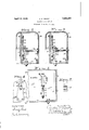
- J Fig. L is. a front view of a thermostatic switchV constructed in accordance with this invention, the casing in which it is contained being sectioned longitudinally;
- Fig. 2 is a sideview thereof, the casing being sectioned transversely and the switch being in.its closed position;
- Fig. 3 is a similar view with the switch in its open position
- Fig. 4 is a detail View showing the guide mem er for the resetting rod.
- Fig. 5 is a detail view of the spring.
- 11 indicates one bf a pair of end castings connected by a bottom member 12 and supporting between them a panel 13 of slate or other suitable insulating material.
- the switch-box thus formed is closed by a bent-over cover plate 14, which is pivotally mounted at the rear of the switchof-swinging open to expose the switches con- ,tained therein, only one of which is here shown, being the thermostatic switch of this invention.
- the various switches contained in the switch-box in the mechanism as designed are those necessary for the automatic operation and control of a gas-engine-operated generating unit of the demand starter type and the thermostatic switch here shown is rovided for automatically opening the cran ing circuit after a period suiiicient for cranking so as to prevent depletion of the battery when for any reason the engine cannot be cranked, as upon the absence of fuel, and this consists of a heating coil 30 secured to a stri of bi-metallic thermostat metal 31 which 1s mounted at one end on theinsulating panel 13 and at the other end carries a contact 32 to engage a contact 32 carried by a lever 33 mounted on a pivot-block 34 and held i eith'er its closed or its open position by an arched spring .35 engaging said pivot-block and a projection of the lever.
- This spring serves to hold the lever in either of its positions by having itsv outer end carried from one side to the other of the line connecting its inner end and the pivotal axis of the lever.
- a resetting rod 36 serving as an indicator ing in the switch cover 14 that the thermostat switch is open, is pivotally mounted on the lever 33 and is guided bypassing through an opening in a guide member 37 mounted on the upwardly extending front flange 38 of the bottom member 12.
- the contacts 32 are included directly or indirectly in the cranking circuit which it is desired to interrupt upon a failure of cranking, and the heating coil 30 of the thermostatic switch for disconnecting said contacts when the engine fails to crank within a reasonable time is in a circuit controlled by the means r box to the end castings 11 so as to be capable lever pivotally strip Lof the generator as a motor, but after a reasonable predetermined time the heating eiiect of the heat coil 30 causes the thermostat 31 to bend and gradually force th-e lever 33 outwardly against the action of spring 35, meanwhile rubbing the contacts together until the spring passes over the dead center and throws the lever to its outermost position, opening the contacts 32 with a snap action and consequently interrupting the cranking circuit.
- a thermal switch comprising a base, a mounted thereon, spring seats formed onl the lever and the base, the line joining which passes through the pivotal axis of the lever in an intermediate osition of the lever, a spring with its ends htting in said spring seats, a contact carried by the lever, a suitably mounted strip of thermostat metal, and a contact carried thereby engaging the contact of the lever.
- a thermal switch comprising an insulating panel, a cover therefor, a base mounted on the panel, a lever pivotally mounted on the base, a bowed spring confined between the base and the lever, the line connecting the ends thereof passing through the pivotal connection of the lever in an intermediate position of the lever, al contact carried by the lever, a strip of thermostat metal mounted on the panel, a contact carried thereby for engaging the other contact, a heating coil Carried by the thermostat metal, and an indicator and resetting rod carried by the lever and projecting through an opening in the cover.
- a thermal switch comprising an insulating panel, a bottom member secured thereto, a removable cover forming an enclosure with the panel andbottom member, a base secured to the panel, a lever fulcrumed on the base, a spring between the base and the lever, the line connecting the ends thereof passing through the fulcrum point of the lever in an intermediate position of the lever,
- a contact carried by the lever a strip of thermostat metal secured to the panel, a heating coil carried thereby, a contact on the thermostat metal engaging the other contact, a guide on the bottom member, and an indicating and resetting rod carried by the lever and Jpassing through the guide and through an opening in the cover.
- a thermal switch comprising a suitably mounted strip of thermostatic metal, an electrical contact carried thereby, a pivotally mounted switch member having dead center Vspring action for urging it to either of two positions,.and an electrical contact on said switch member for engaging the electrical contact of the strip ofthermostat metal, said switch member being responsive to slow action of the strip of thermostat metal and when moved thereby to a' 'certain point bein automatically carried beyond that point wit a quick action eecting a speedy opening of the electrical contacts.
Landscapes
- Engineering & Computer Science (AREA)
- Power Engineering (AREA)
- Connection Of Motors, Electrical Generators, Mechanical Devices, And The Like (AREA)
- Switch Cases, Indication, And Locking (AREA)
- Thermally Actuated Switches (AREA)
Description
April12,19sz. A, F, BROTZ 5 '1,853,957
' THERMOSTATIC SWITCH Original Filed Oct. 5' 1925 G. 2 E1-CG.. 3
w1 TNES SES @am M8/www@ Patented 'Api'. 12, 1932 UNITED STATES lPA'rraN'r OFFICE,
.ANTONIFRANIKl BROTZ, OF KOHLER, WISCONSIN, ASSIGNOR T KOHLECR COMPANY, 0F A KHLER, WISCONSIN, A CORPORATION 0F WIISCOII'YSIFIV rnnnuos'ra'ric SWITCH Original application led October 5, 1925, Serial No. 60,702. Divided and this application led March 31,
. 1927. Serial No. 179,934?. l
This invention relates to thermostaticswitches for effecting fthe opening or closlng of anelectrical circuit'- with a snap action.
An object of the invention is to provide a switch member responsive to slow Aaction of a thermostatic or heat element and which, when moved thereby to a certain point, will be au'- tomatically carried beyond that point with lll a quick action effecting' a speedy operation of the switch. f
.Another object. of the invention is to provide a thermostatic switch of this character required to be reset by hand for compelling attention to the condition responsible for the temperature change causing the operation.
Afurtherobject is to utilize a bow spring for holding theswitch member with spring .pressure in either its open or closed position.
- rAnother object of the invention is to provide such a thermostatic switch particularly designed for disconnecting the cranking 'circuit of a gas-engine-operated generating unit of the demand starter type when cranking is ineii'ective.
This case constitutes a division of my application for Automatic generating plants, Serial No. 60,702, filed October 5, 1925.
'With the above and other objects in view the invention consists in the thermostatic switch as herein claimed and all equivalents.
Referring to the accompanying drawings in which like characters of reference indicate the same parts in different views, J Fig. L is. a front view of a thermostatic switchV constructed in accordance with this invention, the casing in which it is contained being sectioned longitudinally;
Fig. 2 is a sideview thereof, the casing being sectioned transversely and the switch being in.its closed position;
Fig. 3 is a similar view with the switch in its open position;
Fig. 4 is a detail View showing the guide mem er for the resetting rod, and
Fig. 5 `is a detail view of the spring.
' In these drawings, 11 indicates one bf a pair of end castings connected by a bottom member 12 and supporting between them a panel 13 of slate or other suitable insulating material.' The switch-box thus formed is closed by a bent-over cover plate 14, which is pivotally mounted at the rear of the switchof-swinging open to expose the switches con- ,tained therein, only one of which is here shown, being the thermostatic switch of this invention.
The various switches contained in the switch-box in the mechanism as designed are those necessary for the automatic operation and control of a gas-engine-operated generating unit of the demand starter type and the thermostatic switch here shown is rovided for automatically opening the cran ing circuit after a period suiiicient for cranking so as to prevent depletion of the battery when for any reason the engine cannot be cranked, as upon the absence of fuel, and this consists of a heating coil 30 secured to a stri of bi-metallic thermostat metal 31 which 1s mounted at one end on theinsulating panel 13 and at the other end carries a contact 32 to engage a contact 32 carried by a lever 33 mounted on a pivot-block 34 and held i eith'er its closed or its open position by an arched spring .35 engaging said pivot-block and a projection of the lever. vThis spring serves to hold the lever in either of its positions by having itsv outer end carried from one side to the other of the line connecting its inner end and the pivotal axis of the lever.
A resetting rod 36, serving as an indicator ing in the switch cover 14 that the thermostat switch is open, is pivotally mounted on the lever 33 and is guided bypassing through an opening in a guide member 37 mounted on the upwardly extending front flange 38 of the bottom member 12.
Without entering into the details of circuit connections vwhich are not essential to an understanding of the present invention, it is sucient to note that the contacts 32 are included directly or indirectly in the cranking circuit which it is desired to interrupt upon a failure of cranking, and the heating coil 30 of the thermostatic switch for disconnecting said contacts when the engine fails to crank within a reasonable time is in a circuit controlled by the means r box to the end castings 11 so as to be capable lever pivotally strip Lof the generator as a motor, but after a reasonable predetermined time the heating eiiect of the heat coil 30 causes the thermostat 31 to bend and gradually force th-e lever 33 outwardly against the action of spring 35, meanwhile rubbing the contacts together until the spring passes over the dead center and throws the lever to its outermost position, opening the contacts 32 with a snap action and consequently interrupting the cranking circuit. In this position the lever 33 is held by the spring 35 with the rod 36 projecting from the cover of the switch-box to ind1cate that the thermostatic switch is open. When the defect has been remedied, as by providing a supply offuel if -that was the cause of the failure to crank, the thermostatic switch has to be reset by hand by pressing the rod 36 inwardly to close the contacts@ What I claim as new and desire to secure by Letters Patent is:
l. A thermal switch comprising a base, a mounted thereon, spring seats formed onl the lever and the base, the line joining which passes through the pivotal axis of the lever in an intermediate osition of the lever, a spring with its ends htting in said spring seats, a contact carried by the lever, a suitably mounted strip of thermostat metal, and a contact carried thereby engaging the contact of the lever.
2. A thermal switch comprising an insulating panel, a cover therefor, a base mounted on the panel, a lever pivotally mounted on the base, a bowed spring confined between the base and the lever, the line connecting the ends thereof passing through the pivotal connection of the lever in an intermediate position of the lever, al contact carried by the lever, a strip of thermostat metal mounted on the panel, a contact carried thereby for engaging the other contact, a heating coil Carried by the thermostat metal, and an indicator and resetting rod carried by the lever and projecting through an opening in the cover.
3. A thermal switch comprising an insulating panel, a bottom member secured thereto, a removable cover forming an enclosure with the panel andbottom member, a base secured to the panel, a lever fulcrumed on the base, a spring between the base and the lever, the line connecting the ends thereof passing through the fulcrum point of the lever in an intermediate position of the lever,
a contact carried by the lever, a strip of thermostat metal secured to the panel, a heating coil carried thereby, a contact on the thermostat metal engaging the other contact, a guide on the bottom member, and an indicating and resetting rod carried by the lever and Jpassing through the guide and through an opening in the cover.
4. A thermal switch comprising a suitably mounted strip of thermostatic metal, an electrical contact carried thereby, a pivotally mounted switch member having dead center Vspring action for urging it to either of two positions,.and an electrical contact on said switch member for engaging the electrical contact of the strip ofthermostat metal, said switch member being responsive to slow action of the strip of thermostat metal and when moved thereby to a' 'certain point bein automatically carried beyond that point wit a quick action eecting a speedy opening of the electrical contacts.
In testimony whereof, I affix' my signature.
Y ANTON FRANK BROTZ.
Priority Applications (1)
| Application Number | Priority Date | Filing Date | Title |
|---|---|---|---|
| US179934A US1853957A (en) | 1925-10-05 | 1927-03-31 | Thermostatic switch |
Applications Claiming Priority (2)
| Application Number | Priority Date | Filing Date | Title |
|---|---|---|---|
| US60702A US1734557A (en) | 1925-10-05 | 1925-10-05 | Automatic generating plant |
| US179934A US1853957A (en) | 1925-10-05 | 1927-03-31 | Thermostatic switch |
Publications (1)
| Publication Number | Publication Date |
|---|---|
| US1853957A true US1853957A (en) | 1932-04-12 |
Family
ID=22031229
Family Applications (3)
| Application Number | Title | Priority Date | Filing Date |
|---|---|---|---|
| US60702A Expired - Lifetime US1734557A (en) | 1925-10-05 | 1925-10-05 | Automatic generating plant |
| US179934A Expired - Lifetime US1853957A (en) | 1925-10-05 | 1927-03-31 | Thermostatic switch |
| US193658A Expired - Lifetime US1808883A (en) | 1925-10-05 | 1927-05-23 | Switch box for automatic generating plants |
Family Applications Before (1)
| Application Number | Title | Priority Date | Filing Date |
|---|---|---|---|
| US60702A Expired - Lifetime US1734557A (en) | 1925-10-05 | 1925-10-05 | Automatic generating plant |
Family Applications After (1)
| Application Number | Title | Priority Date | Filing Date |
|---|---|---|---|
| US193658A Expired - Lifetime US1808883A (en) | 1925-10-05 | 1927-05-23 | Switch box for automatic generating plants |
Country Status (1)
| Country | Link |
|---|---|
| US (3) | US1734557A (en) |
Cited By (2)
| Publication number | Priority date | Publication date | Assignee | Title |
|---|---|---|---|---|
| US2519629A (en) * | 1946-10-30 | 1950-08-22 | Rotax Ltd | Electric circuit breaker |
| US3674952A (en) * | 1969-10-27 | 1972-07-04 | Ellenberger & Poensgen | Lockswitch |
-
1925
- 1925-10-05 US US60702A patent/US1734557A/en not_active Expired - Lifetime
-
1927
- 1927-03-31 US US179934A patent/US1853957A/en not_active Expired - Lifetime
- 1927-05-23 US US193658A patent/US1808883A/en not_active Expired - Lifetime
Cited By (2)
| Publication number | Priority date | Publication date | Assignee | Title |
|---|---|---|---|---|
| US2519629A (en) * | 1946-10-30 | 1950-08-22 | Rotax Ltd | Electric circuit breaker |
| US3674952A (en) * | 1969-10-27 | 1972-07-04 | Ellenberger & Poensgen | Lockswitch |
Also Published As
| Publication number | Publication date |
|---|---|
| US1808883A (en) | 1931-06-09 |
| US1734557A (en) | 1929-11-05 |
Similar Documents
| Publication | Publication Date | Title |
|---|---|---|
| GB480655A (en) | Automatic installation switch with bi-metal release | |
| US1492967A (en) | Automatic cut-out | |
| US1881884A (en) | Warken noble | |
| US1853957A (en) | Thermostatic switch | |
| US2340877A (en) | Thermal responsive circuit controller | |
| US1839935A (en) | Electric thermostat | |
| US1726233A (en) | Motor-starting switch | |
| US2233187A (en) | Circuit breaker | |
| US2370340A (en) | Circuit breaker | |
| US3038047A (en) | Ambient temperature compensated circuit breaker | |
| US2567361A (en) | Manually operable thermostatic switch assembly | |
| US2529652A (en) | Limit switch | |
| GB439242A (en) | Improvements in, or relating to, release mechanism for electrical switchgear | |
| US1952129A (en) | Circuit breaker | |
| US2157857A (en) | Thermostat | |
| US2201328A (en) | Oil burner control | |
| US2487276A (en) | Temperature control switch | |
| US3683305A (en) | Protective device for air conditioners | |
| US2564868A (en) | Temperature control thermostatic switch device | |
| US1962587A (en) | Thermostatic contact mechanism | |
| US1558101A (en) | Gesellschaet | |
| US1719089A (en) | Electrical apparatus | |
| US2307823A (en) | Circuit breaker | |
| US2343862A (en) | Thermal relay unit | |
| US1973253A (en) | Switch structure |