US185394A - Improvement in processes and machines for treating bricks - Google Patents
Improvement in processes and machines for treating bricks Download PDFInfo
- Publication number
- US185394A US185394A US185394DA US185394A US 185394 A US185394 A US 185394A US 185394D A US185394D A US 185394DA US 185394 A US185394 A US 185394A
- Authority
- US
- United States
- Prior art keywords
- brick
- bricks
- knives
- bed
- knife
- Prior art date
- Legal status (The legal status is an assumption and is not a legal conclusion. Google has not performed a legal analysis and makes no representation as to the accuracy of the status listed.)
- Expired - Lifetime
Links
- 239000011449 brick Substances 0.000 title description 40
- 238000000034 method Methods 0.000 title description 9
- 241001137251 Corvidae Species 0.000 description 1
- 239000011469 building brick Substances 0.000 description 1
- 238000001035 drying Methods 0.000 description 1
- 239000000428 dust Substances 0.000 description 1
- 239000013013 elastic material Substances 0.000 description 1
- 230000001771 impaired effect Effects 0.000 description 1
- 238000000465 moulding Methods 0.000 description 1
- 239000002245 particle Substances 0.000 description 1
Images
Classifications
-
- B—PERFORMING OPERATIONS; TRANSPORTING
- B29—WORKING OF PLASTICS; WORKING OF SUBSTANCES IN A PLASTIC STATE IN GENERAL
- B29C—SHAPING OR JOINING OF PLASTICS; SHAPING OF MATERIAL IN A PLASTIC STATE, NOT OTHERWISE PROVIDED FOR; AFTER-TREATMENT OF THE SHAPED PRODUCTS, e.g. REPAIRING
- B29C39/00—Shaping by casting, i.e. introducing the moulding material into a mould or between confining surfaces without significant moulding pressure; Apparatus therefor
- B29C39/02—Shaping by casting, i.e. introducing the moulding material into a mould or between confining surfaces without significant moulding pressure; Apparatus therefor for making articles of definite length, i.e. discrete articles
- B29C39/10—Shaping by casting, i.e. introducing the moulding material into a mould or between confining surfaces without significant moulding pressure; Apparatus therefor for making articles of definite length, i.e. discrete articles incorporating preformed parts or layers, e.g. casting around inserts or for coating articles
-
- B—PERFORMING OPERATIONS; TRANSPORTING
- B28—WORKING CEMENT, CLAY, OR STONE
- B28B—SHAPING CLAY OR OTHER CERAMIC COMPOSITIONS; SHAPING SLAG; SHAPING MIXTURES CONTAINING CEMENTITIOUS MATERIAL, e.g. PLASTER
- B28B11/00—Apparatus or processes for treating or working the shaped or preshaped articles
- B28B11/08—Apparatus or processes for treating or working the shaped or preshaped articles for reshaping the surface, e.g. smoothing, roughening, corrugating, making screw-threads
- B28B11/0818—Apparatus or processes for treating or working the shaped or preshaped articles for reshaping the surface, e.g. smoothing, roughening, corrugating, making screw-threads for roughening, profiling, corrugating
Definitions
- Buildingbricks when formed in the ordinary manner, by molding or pressing, are not uniform in thickness, their sides and edges are generally more or less uneven, and they frequently change form in drying or setting, previous to burning, so that even when turned out true by the press their form is generally more or less distorted and impaired, when ready for the kiln.
- the object of my invention is to overcome these difficulties, so as to produce bricks having uniform thickness, and true sides and edges.
- the first part of my invention relates to the process of treating the bricks previous to burning; and the second part of my invention relates to a machine for carrying out this process.
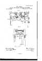
- Figure 1 is a side elevation of my improved machine.
- Fig. 2 is a plan view thereof, with a portion .of the upper parts removed.
- Fig. 3 isalongitudinal section of my machine.
- Fig. 4 is a cross-section in line mm, Fig. 3.
- A represents the main frame of the machine, preferably mounted on wheels at a, so as to be readily moved.
- a. are longitudinal beams or girders secured between the posts of the main frame, and B bed-pieces arranged transversely upon the beams a for supporting the brick while operated upon.
- the bedpiece B is composed of two or more parallel bars arranged so as to leave a narrow opening or space between each pair ofbars, through which the particles separated from the brick may drop.
- B represents a stop plate or abutment arranged on the side of each bedpiece B, and 0 a movable clamping-jaw arranged on the opposite side thereof, for holding the brick to be operated upon between them.
- the stationary and movable jaws are so constructed as to leave the upper and lower edges of the clamped brick free, as these edges frequently project more or less, and would interfere with the proper clamping of the brick.
- the stationary jaws B are arranged at a short distance from the adjacent bed-piece B, so as to leave a narrow space between them through which the dust, 860., can escape.
- D are two horizontal ways or guides, in which the ends of the movable jaws O G are guided, and d d spiral springs arranged around horizontal bolts or rods d, so as to bear against the jaw G, and resist the opening thereof.
- the bolts d are guided in lugs e secured to the main frame.
- E is a hand-lever pivoted to the main frame, and connected to both movable jaws G O by connecting-rodsff, so that both are opened and closed simultaneously. ferred, however, each jaw may be actuated independent of the other.
- G represents the knives or cutters arranged in a reciprocating carriage, H, sliding on horizontal guide-bars h, by means of bearings h are adjustahly secured to frames I pivoted between lugs 70 of the carriage H.
- Two knives or cutters, G are arranged above each bedpiece B, preferably in such manner that the knives will travel partially over the same from opposite sides, so that each knife will cut or plane the brick placed on the bed-piece from its edge inwardly, and stop before reaching the opposite .edge of the brick.
- the knives are adjusted on the frames I by set-screws i passing through slots in the knives, and with reference to the carriage H, by set-screws h passing through cross pieces h of the carriage.
- L are springs arranged at one or both ends of each knife G, for holding the same in contact with the brick during the cuttingstroke, and lifting it away from the brick during its return stroke.
- the springs L consist of a vertical arm secured to the main frame, and a horizontal arm, l, arranged at a short distance above the cutting-edge of the respective knife, and provided with an inwardly-projecting portion, l. The latter bears against the end ofthe knife during its forward or cutting stroke, thereby holding the knife down If me.
- the knives G to its work, while, when the knife has completed its stroke, the portion 1 springs inward, and engages against the back of the knife, thereby raising the latter during-its return stroke, so that the cutting-edge clears the brick until the end of the portion 1 of the spring is reached by the knife, when it drops back to its former position by its own weight.
- the cutter-carriage H as shown in the drawings, is actuated by a bell-crank lever, K, but any other suitable means may be employed for the purpose.
- the bed-pieces B, abutinents B, and clampingawsv O are preferably arranged at an angle to the knives, so that the latter strike the brick in an oblique direction, which produces a slanting cut, and brings the resistance gradually upon the knives.
- 1' represents sleeves of rubber or other elastic material placed upon the guide-bars h, so that the bearings h of the carriage H will come in contact therewith at the end of its stroke, and arrest the movement of the carriage in an easy manner.
- the bricks formed-in the mold or pressed in the ordinary manner are allowed to dry or set unlil they are ready for burning, when they are subjected to the action of my improved machine.
- the brick to be operated upon is placed upon the bed-piece B, and clamped by closing the movable jaw O, the two knives being in a position equidistant from the central line of the bed-piece.
- the knife-carriage H is then reciprocated, so that each knife makes a complete forward and backward stroke, whereby the upper surface of the brick is planed off.
- the two knives cut successively inwardly from the edge of the brick, and stop before reaching the opposite edge of the brick, whereby theentire face of the brick is completely gone over, and, at the same time, the chipping or breaking off of edge is avoided, which would take place if the knives were run over the edge opposite to that from which they start.
- the clamping-jaw O is opened and the brick reversed and clamped again, and the operation of planing repeated.
- the sides of the brick which are placed horizontally when the bricks are laid in a wall are made true and even, and the bricks are made of a uniform thickness, so that they can be laid without previously sorting them, thereby sav ing time in laying them, and enabling them to be laid in perfectly straight courses, with well-defined joints, with ease and despatch.
- the machine is provided with two bed-pieces, B, as shown in the drawings, two operators are employed on the same, one feeding the bricks from one side onto the first bed-piece, Where one side of thebrick is planed off, while the other operator takes the brick from the first bedpiece, and places it in a reversed position on the second bed-piece, where the other side of the brick is planed off.
- The-machine is readily moved from one part of the yard to another, as circumstances may require; but, if preferred, may be made stationary and driven by any suitable power.
Landscapes
- Engineering & Computer Science (AREA)
- Structural Engineering (AREA)
- Chemical & Material Sciences (AREA)
- Ceramic Engineering (AREA)
- Mechanical Engineering (AREA)
- Press-Shaping Or Shaping Using Conveyers (AREA)
Description
2 Sheets-Sheet 1.
W. C. HALL. PROCESS AND MACHINE FOR TREATING BRICK. No.185,394.-, Patented Dec. 19, 1876-.
THE GRAPHIC OOJLY {Sheets-Sheet 2.
W. C. HALL. PROCESS AND MACHINE FOR TREATING BRICK. No.185,394. Patented Dec.19, 1876.
jays.
N 4/ kl Y 4 THE GRAPHIC OO-N-Y Unrrnn s'ra'rne WILLIAM G. HALL, OF
Parana @rrroa.
BUFFALO, NEW YORK.
IMPROVEMENT IN PROCESSES AND MACHINES FOR TREATING BRICKS.
Specification forming part of Letters Patent No. 185,394, dated December 19, 1876; application filed October 23, 1876.
To all whom it may concern:
Be it known that 1, WILLIAM G. HALL, of the city of Buffalo, in the county of Erie and State of New York, have invented certain Improvements in Process and Machine-for Treating Bricks, which improvements are fully set forth in the following specification, reference being bad to the accompanying drawings.
Buildingbricks, when formed in the ordinary manner, by molding or pressing, are not uniform in thickness, their sides and edges are generally more or less uneven, and they frequently change form in drying or setting, previous to burning, so that even when turned out true by the press their form is generally more or less distorted and impaired, when ready for the kiln.
The object of my invention is to overcome these difficulties, so as to produce bricks having uniform thickness, and true sides and edges.
The first part of my invention relates to the process of treating the bricks previous to burning; and the second part of my invention relates to a machine for carrying out this process.
The nature of my invention will be fully understood from the following description.
In the accompanying drawings, consisting of two sheets, Figure 1 is a side elevation of my improved machine. Fig. 2 is a plan view thereof, with a portion .of the upper parts removed. Fig. 3isalongitudinal section of my machine. Fig. 4 is a cross-section in line mm, Fig. 3.
Like letters of reference refer to like parts in each of the figures.
A represents the main frame of the machine, preferably mounted on wheels at a, so as to be readily moved. a. are longitudinal beams or girders secured between the posts of the main frame, and B bed-pieces arranged transversely upon the beams a for supporting the brick while operated upon. The bedpiece B is composed of two or more parallel bars arranged so as to leave a narrow opening or space between each pair ofbars, through which the particles separated from the brick may drop. B represents a stop plate or abutment arranged on the side of each bedpiece B, and 0 a movable clamping-jaw arranged on the opposite side thereof, for holding the brick to be operated upon between them. The stationary and movable jaws are so constructed as to leave the upper and lower edges of the clamped brick free, as these edges frequently project more or less, and would interfere with the proper clamping of the brick. The stationary jaws B are arranged at a short distance from the adjacent bed-piece B, so as to leave a narrow space between them through which the dust, 860., can escape. D are two horizontal ways or guides, in which the ends of the movable jaws O G are guided, and d d spiral springs arranged around horizontal bolts or rods d, so as to bear against the jaw G, and resist the opening thereof. The bolts d are guided in lugs e secured to the main frame. E is a hand-lever pivoted to the main frame, and connected to both movable jaws G O by connecting-rodsff, so that both are opened and closed simultaneously. ferred, however, each jaw may be actuated independent of the other. G represents the knives or cutters arranged in a reciprocating carriage, H, sliding on horizontal guide-bars h, by means of bearings h are adjustahly secured to frames I pivoted between lugs 70 of the carriage H. Two knives or cutters, G, are arranged above each bedpiece B, preferably in such manner that the knives will travel partially over the same from opposite sides, so that each knife will cut or plane the brick placed on the bed-piece from its edge inwardly, and stop before reaching the opposite .edge of the brick. The knives are adjusted on the frames I by set-screws i passing through slots in the knives, and with reference to the carriage H, by set-screws h passing through cross pieces h of the carriage. L are springs arranged at one or both ends of each knife G, for holding the same in contact with the brick during the cuttingstroke, and lifting it away from the brick during its return stroke. The springs L consist of a vertical arm secured to the main frame, and a horizontal arm, l, arranged at a short distance above the cutting-edge of the respective knife, and provided with an inwardly-projecting portion, l. The latter bears against the end ofthe knife during its forward or cutting stroke, thereby holding the knife down If me.
The knives G to its work, while, when the knife has completed its stroke, the portion 1 springs inward, and engages against the back of the knife, thereby raising the latter during-its return stroke, so that the cutting-edge clears the brick until the end of the portion 1 of the spring is reached by the knife, when it drops back to its former position by its own weight. The cutter-carriage H, as shown in the drawings, is actuated by a bell-crank lever, K, but any other suitable means may be employed for the purpose.
The bed-pieces B, abutinents B, and clampingawsv O are preferably arranged at an angle to the knives, so that the latter strike the brick in an oblique direction, which produces a slanting cut, and brings the resistance gradually upon the knives. 1' represents sleeves of rubber or other elastic material placed upon the guide-bars h, so that the bearings h of the carriage H will come in contact therewith at the end of its stroke, and arrest the movement of the carriage in an easy manner.
The bricks formed-in the mold or pressed in the ordinary manner are allowed to dry or set unlil they are ready for burning, when they are subjected to the action of my improved machine.
The brick to be operated upon is placed upon the bed-piece B, and clamped by closing the movable jaw O, the two knives being in a position equidistant from the central line of the bed-piece. The knife-carriage H is then reciprocated, so that each knife makes a complete forward and backward stroke, whereby the upper surface of the brick is planed off. The two knives cut successively inwardly from the edge of the brick, and stop before reaching the opposite edge of the brick, whereby theentire face of the brick is completely gone over, and, at the same time, the chipping or breaking off of edge is avoided, which would take place if the knives were run over the edge opposite to that from which they start. When one side of the brick is finished, the clamping-jaw Ois opened and the brick reversed and clamped again, and the operation of planing repeated. in this manner the sides of the brick, which are placed horizontally when the bricks are laid in a wall are made true and even, and the bricks are made of a uniform thickness, so that they can be laid without previously sorting them, thereby sav ing time in laying them, and enabling them to be laid in perfectly straight courses, with well-defined joints, with ease and despatch.
When the bricks are provided with a sunken panel on one or both sides, the planing will extend only to the marginal portion surrounding the panel. WVhen the machine is provided with two bed-pieces, B, as shown in the drawings, two operators are employed on the same, one feeding the bricks from one side onto the first bed-piece, Where one side of thebrick is planed off, while the other operator takes the brick from the first bedpiece, and places it in a reversed position on the second bed-piece, where the other side of the brick is planed off.
- The-machine is readily moved from one part of the yard to another, as circumstances may require; but, if preferred, may be made stationary and driven by any suitable power.
Having thus fully described my invention, what I claim as new, and desire to secure by Letters Patent, is-
1. The herein-described process of preparing bricks for the kiln by first forming the bricks in any suitable mold or press, then allowing the bricks so formed to set or harden, and then planing ofi' the sides 'or horizontal surfaces of the bricks, substantially as and for the purpose hereinbefore set forth.
2. The herein-described process of planing the surface of green bricks from two opposite edges, inwardly, whereby the chipping 011' of the edges is prevented, substantially as hereinbefore set forth.
3. The combination, with the bed-piece B, of two reciprocating hinged knives, G G, cutting in opposite directions, substantially as and for the purpose hereinbefore set forth.
4. The combination, with a hinged knife, G, of a spring-arm, L, provided with an inwardly-projecting portion, l, for holding the knife down to the brick during the cuttingstroke, and raising it away from the brick during the return stroke, substantially as hereinbefore set forth.
5. The combination, with one or more bedpieces, B, of the abutment B, movable clamp G, and reciprocating carriage H, provided with one or more pairs of hinged knives, G, substantially as and for the purpose hereinbefore set forth. 7
6. The combination, with the bed B, and fixed jaw B, of the movable clamping-jaw G, sliding in guides D, guide-bars d, springs d, and actuating lever, substantially as and for the purpose hereinbefore set forth.
7. The combination, with the reciprocating I hinged knives G, of the bed-piece B, provided 9. The combination, with one or more bedpieces B, of the reciprocating carriage H, provided with knives G, and supported by bearings l1, upon guide-bars h, having elastic cushions r, substantially as and for the purpose hereinbefore set forth.
WM. 0. HALL.
Witnesses:
GEO. H. SYKEs, EDWARD WILHELM.
Publications (1)
| Publication Number | Publication Date |
|---|---|
| US185394A true US185394A (en) | 1876-12-19 |
Family
ID=2254800
Family Applications (1)
| Application Number | Title | Priority Date | Filing Date |
|---|---|---|---|
| US185394D Expired - Lifetime US185394A (en) | Improvement in processes and machines for treating bricks |
Country Status (1)
| Country | Link |
|---|---|
| US (1) | US185394A (en) |
-
0
- US US185394D patent/US185394A/en not_active Expired - Lifetime
Similar Documents
| Publication | Publication Date | Title |
|---|---|---|
| US185394A (en) | Improvement in processes and machines for treating bricks | |
| US2559378A (en) | Machine for the manufacture of small floor-parqueting blocks | |
| US590836A (en) | Double planer and sander | |
| US565463A (en) | Chipper | |
| US2644944A (en) | Means for strapping boxes | |
| US943971A (en) | Machine for making cement tiles. | |
| US548A (en) | Machine fob molding bricks | |
| US1560808A (en) | Shearing machine for metal sheets | |
| US90285A (en) | George a | |
| US1024409A (en) | Shearing-machine. | |
| US1017461A (en) | Cutting-out and molding machine. | |
| US375904A (en) | Machine for cutting moldings | |
| US740727A (en) | Head-block-sawing machine. | |
| US139409A (en) | Improvement in machines for planing stone | |
| US351219A (en) | Minard m | |
| US795725A (en) | Machine for making plastic blocks. | |
| US145376A (en) | Improvement in machines for cutting and dressing stone | |
| US840006A (en) | Machine for making concrete building-blocks. | |
| US332474A (en) | Brick-machine | |
| US50602A (en) | Improvement in wood-bending machines | |
| US786560A (en) | Veneer-cutting machine. | |
| US3268383A (en) | Apparatus for producing continuous chipboard sheets or panels | |
| US732857A (en) | Sheet-metal-pipe former and groover. | |
| US1860584A (en) | Method of and means for closing the ends of the channels of molded hollow channel bricks and building blocks | |
| US487348A (en) | Molding and blind-slat-planing machine |