US1853947A - Apparatus for straightening lead wires - Google Patents
Apparatus for straightening lead wires Download PDFInfo
- Publication number
- US1853947A US1853947A US545058A US54505831A US1853947A US 1853947 A US1853947 A US 1853947A US 545058 A US545058 A US 545058A US 54505831 A US54505831 A US 54505831A US 1853947 A US1853947 A US 1853947A
- Authority
- US
- United States
- Prior art keywords
- wire
- feeler
- wires
- sleeve
- feelers
- Prior art date
- Legal status (The legal status is an assumption and is not a legal conclusion. Google has not performed a legal analysis and makes no representation as to the accuracy of the status listed.)
- Expired - Lifetime
Links
- WABPQHHGFIMREM-UHFFFAOYSA-N lead(0) Chemical compound [Pb] WABPQHHGFIMREM-UHFFFAOYSA-N 0.000 description 2
- 238000000034 method Methods 0.000 description 2
- 241000982285 Adansonia rubrostipa Species 0.000 description 1
- 235000005288 Annona lutescens Nutrition 0.000 description 1
- 241000886928 Annona reticulata Species 0.000 description 1
- 241000489861 Maximus Species 0.000 description 1
- 101100210328 Mus musculus Wipf2 gene Proteins 0.000 description 1
- 230000006835 compression Effects 0.000 description 1
- 238000007906 compression Methods 0.000 description 1
- 241000894007 species Species 0.000 description 1
Images

Classifications
-
- B—PERFORMING OPERATIONS; TRANSPORTING
- B21—MECHANICAL METAL-WORKING WITHOUT ESSENTIALLY REMOVING MATERIAL; PUNCHING METAL
- B21F—WORKING OR PROCESSING OF METAL WIRE
- B21F1/00—Bending wire other than coiling; Straightening wire
- B21F1/02—Straightening
Definitions
- Means are LJNITED STATES PATENT -Cil-"FICE- Jo- Juanma vn m rom. am namens eoos'ms. or imrnnovim.
- Our invention relates to apparatus f or straightening the lead wires o unbased mcandescent electric lamps and similar devices so as to facilitate the threading of such wires 5 through the' bases which are subsequently ap-A plied.
- This requires that the said lead wires extend in the pro er direction and that they be free yfrom k'
- Such wires are ordinarily ringy and must be given a permanent 'lo set during the straightening operation.
- object of our invention is to provide apparatus for stretching the wire to take out the kinks and for giving the wire van extra hard final pull to give it a permanent set.
- the feeler is then rocked to force the lead wire along the guide until it extends in approximatelythe required direction.
- the wire is then gripped between the end of the feeler and a gripping member which, with the feeler is movably rovided for causing the end of the feeler to c amp the wire against the saidmember.v
- the feeler and cooperating .30 member are then mvedaway from the lamp or other device to stretch the wire and take out l the kinks.
- This stretching is (preferably over -a stationary support locate adjacent the end of the' lamp or similar device carrying v the wires.
- the pull on the clamping members is such that they slip over the wire until they reach a position near its end when means come intooperation for forcing the feeler into firmer contact with its cooperating member and causing it to grip the wire more firmly than before.
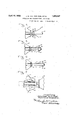
- Fig. 1 is an elevation, partly sectioned, of the device embodying our ⁇ invention.
- Figs. 2 and 3 are front e evations showing feelers comprised in said device in different positions; and Figs. 4 5, 6 and 7 show different steps in the straightenin process.
- a bulb 10 of an incandescent electric'lamp with leading-in wires 11 is placed against a knob 12 at the end of .
- 4Feelers 14 Fig. 2
- This position is shown in Fig. .4.
- the lower ends of feelers 14 engage a collar 26 on sleeve 25 so that said sleeve 25 moves to the left in Fig. 1 with said feelers 14.
- a spring 27 provides the return movement for sleeve 25.
- the sleeves ⁇ 25 and 21 are held from rotating by a key 28 which is fastened to sleeve 25 and rides in a slot in the sleeve 21 and in slot 29 in the fixed shaft 1 3.
- Fig. 5 shows anl intermediate position in the travel of feelers 14 and sleeve 25 with the wires 11 held between them.
- the plungers 22 are pushed back against the wire before the grippingv device slips oifsprings 30 in the housings 31, which are held of it. This gives the wire a permanent set. by an arm 32 mounted inthe ,frame of the 45 ⁇ Various other features and advantages of our machine (not shown).
- pllhe compression of springs causes feelers 14 to push wires 11 more rmly'into grooves 24 of sleeve ⁇ 25 as said feelers move to the left, thus causing wires 11 to be gripped more and more firmly.
- a collar 33 on each of the plungersv 22 comes in contact with a sleeve 34 which compresses a sprinr 35.
- FIG. 6 shows the position in which the feelers 14 have just slid od the ends of wires 11.
- the feelers 14 are now moved to the right in Fig. 1 by the arm 19 and are also rotated about the fixed bushing 36, thus placing them in the position shown in Fig. 2 where they are again ready to repeat the process.
- feelersv 14 in the position shown in Fig. 2, rotate in the direction of the arrow, engage each of the wires 11 and place them against each of guide stops 16. Said feelers. 14 in the position shown in dotted linesin Fig. 1, now move to the left so that their upper ends strike plungers 22, held forward by springs 30, and their lower ends push the wires 11 into grooves 24 of the movl able sleeve 25.
- the feelers 14 and sleeve 25 continue to move to the left with the wires 11 held between them and just before leaving said wires 11, said feelers 14 are pressed against the wires with sufficiently greater force, due to a second spring 35, to cause said wires 11 to be given an extra hard pull by the subsequent movement of said feelers 14 and i sleeve 25 and to acquire a permanent set.
- an apparatus for straightening a wire extending from a device the combination of means for supporting said device, a movable member mounted adjacent to said device and carrying a' pivotally mounted feeler having one end thereof shaped to grip a wire, a guide and a gripping member mounted so as to cooperate with the end of said feeler, means for reciprocating said movable member to'- ward and away from said device, means for causing said feeler to vengage said wire and move it into engagement with said guide means for then causmg said feeler to be tilte to cause its end to clamp said wire against said gripping member, and means for causing an increased pressure of said feeler against said gripping member as the end of said wire is reached.
Landscapes
- Engineering & Computer Science (AREA)
- Mechanical Engineering (AREA)
- Wire Processing (AREA)
Description
April 12, 1932. J. M. VAN DER Pol-:L E1- Al. 1,853,947
APPARATUS Foa STRAIGHTENING LEAD wIREs l Filed June' 17. 1931 2 shees-sheety 1 Inventors: Y l Johannes M.v.o.poel, Henricus Gooskens,
Their` Attorne'g April A12, 1932.
.1. M. VANDER PoEl. ET Al.
APIARATUS FOR STRAIGHTENING LEAD WIRES Filgd June 17. 1931 l 2 sheets-sheet 2 .ps 00.0. eMs .veuA nec Ih nm .a my, .u .J. 4 N 2 0,. 7. l? -l m Their- Attornegg.
. supported. Means are LJNITED STATES PATENT -Cil-"FICE- Jo- Juanma vn m rom. am namens eoos'ms. or imrnnovim.
' mamans,
naw zoax maximus ron sra'axenrnme Laan wmas Application lled June 1'?, 1881, Serial lo. 545,058, and in the Netherlands June 98, 1981. `v
' Our invention relates to apparatus f or straightening the lead wires o unbased mcandescent electric lamps and similar devices so as to facilitate the threading of such wires 5 through the' bases which are subsequently ap-A plied. This requires that the said lead wires extend in the pro er direction and that they be free yfrom k' Such wires are ordinarily ringy and must be given a permanent 'lo set during the straightening operation. An
object of our invention is to provide apparatus for stretching the wire to take out the kinks and for giving the wire van extra hard final pull to give it a permanent set.
According to our invention, we provide pivotally` mounted feelers and cooperatmg guides so mounted that the feeler may be i moved in a horizontal plane to engage a lead wire which may extend from the 'lamp in most any direction and to move said wire into engagement with a guide. The feeler is then rocked to force the lead wire along the guide until it extends in approximatelythe required direction. The wire is then gripped between the end of the feeler and a gripping member which, with the feeler is movably rovided for causing the end of the feeler to c amp the wire against the saidmember.v The feeler and cooperating .30 member are then mvedaway from the lamp or other device to stretch the wire and take out l the kinks. This stretching is (preferably over -a stationary support locate adjacent the end of the' lamp or similar device carrying v the wires. As the wire straightens out, the pull on the clamping members is such that they slip over the wire until they reach a position near its end when means come intooperation for forcing the feeler into firmer contact with its cooperating member and causing it to grip the wire more firmly than before.
The result is that an extra hard pull 'is given@ invention will appear from the following de detailed description of species thereof. In the drawmgs Fig. 1 is an elevation, partly sectioned, of the device embodying our `invention. Figs. 2 and 3 are front e evations showing feelers comprised in said device in different positions; and Figs. 4 5, 6 and 7 show different steps in the straightenin process.
eferring to Fig. 1, a bulb 10 of an incandescent electric'lamp with leading-in wires 11 is placed against a knob 12 at the end of .A BSIGNOBB T GENERAL ELECTRIC COMPANY, A. @EPURATION 'QI v a stationary shaft 13. 4Feelers 14 Fig. 2)
' withtheir support 15 rotate in the irection of the arrows (drive not shown) engage each of the lead wires 11 and place each of them against a ide stop 16'. This brings said' feelers 14 into the position shown in dotted lines-i in Fig. 1,with their lower ends held up by springs 17 fastened to pins 18 in feeler support 15, The feelers 14 are now moved to the left in Fig. 1 by an .arm19`through a'sleeve 20 upon which the supportv 15 is mounted. Stops 16 also are moved to the left, being mounted on a sleeve 21 which is locked between the sleeve 20 and support 15. The top parts of feelers 14 -strike plungers 22 and pivot about pins 23 .in support 15, thus pushing the wires 11 into grooves 24 of the movable sleeve 25.4 This position is shown in Fig. .4. The lower ends of feelers 14 engage a collar 26 on sleeve 25 so that said sleeve 25 moves to the left in Fig. 1 with said feelers 14. A spring 27 provides the return movement for sleeve 25. The sleeves`25 and 21 are held from rotating by a key 28 which is fastened to sleeve 25 and rides in a slot in the sleeve 21 and in slot 29 in the fixed shaft 1 3.' Fig. 5 shows anl intermediate position in the travel of feelers 14 and sleeve 25 with the wires 11 held between them.
The plungers 22 are pushed back against the wire before the grippingv device slips oifsprings 30 in the housings 31, which are held of it. This gives the wire a permanent set. by an arm 32 mounted inthe ,frame of the 45` Various other features and advantages of our machine (not shown). pllhe compression of springs causes feelers 14 to push wires 11 more rmly'into grooves 24 of sleeve `25 as said feelers move to the left, thus causing wires 11 to be gripped more and more firmly. Just before feelers 14 slide ofi' the ends of wires 11, a collar 33 on each of the plungersv 22 comes in contact with a sleeve 34 which compresses a sprinr 35. This compresslon of spring 35 causes faeelers 14 to grip wires 1l so firmly that'during the further movement of said feelers and sleeve 25 the wires 11 are given an extra hard pull. Fig. 6 shows the position in which the feelers 14 have just slid od the ends of wires 11. The feelers 14 are now moved to the right in Fig. 1 by the arm 19 and are also rotated about the fixed bushing 36, thus placing them in the position shown in Fig. 2 where they are again ready to repeat the process.
In operation, feelersv 14, in the position shown in Fig. 2, rotate in the direction of the arrow, engage each of the wires 11 and place them against each of guide stops 16. Said feelers. 14 in the position shown in dotted linesin Fig. 1, now move to the left so that their upper ends strike plungers 22, held forward by springs 30, and their lower ends push the wires 11 into grooves 24 of the movl able sleeve 25. The feelers 14 and sleeve 25 continue to move to the left with the wires 11 held between them and just before leaving said wires 11, said feelers 14 are pressed against the wires with sufficiently greater force, due to a second spring 35, to cause said wires 11 to be given an extra hard pull by the subsequent movement of said feelers 14 and i sleeve 25 and to acquire a permanent set.
lWhat we claim as new and desire to secure by Letters Patent of the United States is; 1. In an apparatus for straightening a wire extending from a device, the combination of means for supporting said device, a movable member mounted adjacent to said device and carrying a pivotally mounted feeler having one end thereof shaped to grip a wire, a guide and a gripping member mounted so as to cooperate with the end of said feeler, means for reciprocating said movable member toward and away from said device, means for causing said feeler to engage said 'wire and move it'into engagement with said guide and means for then causing said feeler to be tilted to cause its end to clamp .said wire against said gripping member.
2. In an apparatus for straightening a wire extending from a device, the combination of means for supporting said device, a movable member mounted adjacent to said device and carrying a' pivotally mounted feeler having one end thereof shaped to grip a wire, a guide and a gripping member mounted so as to cooperate with the end of said feeler, means for reciprocating said movable member to'- ward and away from said device, means for causing said feeler to vengage said wire and move it into engagement with said guide means for then causmg said feeler to be tilte to cause its end to clamp said wire against said gripping member, and means for causing an increased pressure of said feeler against said gripping member as the end of said wire is reached.
3. In an apparatus of the class described, the combination of means for supporting a device having leads extending therefrom, a stationary support, a movable sleeve carrying a pivotally mounted feeler having one end thereof shaped to grip a wire, a guide and a gripping member mounted so as to cooperate with the end of said feeler, means -for reciprocating said sleeve toward and away from said device, means for causing said feeler to engage said wire and move 1t into engagement with said guide and means for then causing said feeler to be tilted to cause its end to clamp said wire against said gripping member.
4. In an apparatus of the class described, the combination of means for supporting a 'device having leads extending therefrom, a stationary support, a movable sleeve carrying a rotatably and pivotally mounted feeler havin one end thereof shaped to grip a wire, a gui e and a gripping member mounted so as to cooperate with the end of said feeler means for reciprocating said sleeve toward and away from said device, means for rotating said feeler to engage said wire and move it into engagement with said guide and means for then causing said feeler'to be tilted to cause its end to clamp said wire against said gripping member.
5. In an apparatus of the class described, the combination of means for supporting a device having leads extending therefrom, a stationary support, a movable sleeve carrying a pivotally mounted feeler having one end thereof shaped to grip a` wire, a guide and a gripping member mounted so as to cooperate with the end of said feeler, means for reciprocating said sleeve toward and away from said device, means for causin said feeler to engage said wire and move 1t into engagement with said guide, means for thencausing said feeler to be tilted to cause its end to clamp said wire against said gripping member, and means for causing an'increased pressure of said feeler against said gripping member as the end of said wire is reached.
6. In an apparatus of the class described,
the combination of means for supporting a.
then ausinlg our hands.
JOHANNES MARINUS van der POI-IL i llll-INRICUS GUOSKENS.
Applications Claiming Priority (1)
| Application Number | Priority Date | Filing Date | Title |
|---|---|---|---|
| NL1853947X | 1931-06-26 |
Publications (1)
| Publication Number | Publication Date |
|---|---|
| US1853947A true US1853947A (en) | 1932-04-12 |
Family
ID=19873182
Family Applications (1)
| Application Number | Title | Priority Date | Filing Date |
|---|---|---|---|
| US545058A Expired - Lifetime US1853947A (en) | 1931-06-26 | 1931-06-17 | Apparatus for straightening lead wires |
Country Status (1)
| Country | Link |
|---|---|
| US (1) | US1853947A (en) |
Cited By (7)
| Publication number | Priority date | Publication date | Assignee | Title |
|---|---|---|---|---|
| US2721373A (en) * | 1948-11-17 | 1955-10-25 | Sylvania Electric Prod | Automatic lead wire threading apparatus |
| US2752957A (en) * | 1955-02-01 | 1956-07-03 | Gen Electric | Filament mounting machine |
| US2979084A (en) * | 1955-11-23 | 1961-04-11 | Sylvania Electric Prod | Wire spreading machine |
| US2993516A (en) * | 1957-08-29 | 1961-07-25 | Sylvania Electric Prod | Lead-in wire orienting apparatus |
| US3013590A (en) * | 1958-10-09 | 1961-12-19 | Westinghouse Electric Corp | Lead-wire orienting and straightening apparatus |
| US3122179A (en) * | 1961-12-06 | 1964-02-25 | Universal Instruments Corp | Transistor handling apparatus |
| US3144889A (en) * | 1961-07-24 | 1964-08-18 | Ibm | Transistor preparation machine |
-
1931
- 1931-06-17 US US545058A patent/US1853947A/en not_active Expired - Lifetime
Cited By (7)
| Publication number | Priority date | Publication date | Assignee | Title |
|---|---|---|---|---|
| US2721373A (en) * | 1948-11-17 | 1955-10-25 | Sylvania Electric Prod | Automatic lead wire threading apparatus |
| US2752957A (en) * | 1955-02-01 | 1956-07-03 | Gen Electric | Filament mounting machine |
| US2979084A (en) * | 1955-11-23 | 1961-04-11 | Sylvania Electric Prod | Wire spreading machine |
| US2993516A (en) * | 1957-08-29 | 1961-07-25 | Sylvania Electric Prod | Lead-in wire orienting apparatus |
| US3013590A (en) * | 1958-10-09 | 1961-12-19 | Westinghouse Electric Corp | Lead-wire orienting and straightening apparatus |
| US3144889A (en) * | 1961-07-24 | 1964-08-18 | Ibm | Transistor preparation machine |
| US3122179A (en) * | 1961-12-06 | 1964-02-25 | Universal Instruments Corp | Transistor handling apparatus |
Similar Documents
| Publication | Publication Date | Title |
|---|---|---|
| US1853947A (en) | Apparatus for straightening lead wires | |
| US1612537A (en) | Leading-in wire-locating device | |
| US2085578A (en) | Filament mounting and mechanism therefor | |
| US2494872A (en) | Method and apparatus for bending tubular glass articles | |
| US2650634A (en) | Lead-in wire orienting apparatus | |
| US2449653A (en) | Filament forming apparatus | |
| US2798514A (en) | Machine for manufacturing tubular lamps | |
| US2372082A (en) | Coiling machine for fine wire | |
| US2124039A (en) | Tongs for removing radio tubes from chassis | |
| US2208970A (en) | Filament mounting apparatus | |
| US2199852A (en) | Mount making machine | |
| US3013590A (en) | Lead-wire orienting and straightening apparatus | |
| US2135288A (en) | Machine for making filament supporting structures | |
| US2604732A (en) | Apparatus for tipping-off sealed envelopes | |
| US2683473A (en) | Method and apparatus for making filament mounts | |
| GB658368A (en) | Improvements in and relating to filament support wire forming apparatus | |
| US2765002A (en) | Lamp lead wire forming apparatus | |
| US2640509A (en) | Filament mounting apparatus | |
| US3000407A (en) | Electric lamp mount making method and apparatus | |
| US1647624A (en) | Machine for and method of mounting filaments | |
| US1434836A (en) | Grid-lining method and machine | |
| US2459513A (en) | Apparatus for making spiders for electric lamps | |
| US2409900A (en) | Fluorescent lighting fixture servicing implement | |
| US2979084A (en) | Wire spreading machine | |
| US1752828A (en) | Method and apparatus for mounting filaments |