US1853939A - Adjustable hoist wing plow - Google Patents
Adjustable hoist wing plow Download PDFInfo
- Publication number
- US1853939A US1853939A US400546A US40054629A US1853939A US 1853939 A US1853939 A US 1853939A US 400546 A US400546 A US 400546A US 40054629 A US40054629 A US 40054629A US 1853939 A US1853939 A US 1853939A
- Authority
- US
- United States
- Prior art keywords
- wing
- slide
- hoist
- blade
- plow
- Prior art date
- Legal status (The legal status is an assumption and is not a legal conclusion. Google has not performed a legal analysis and makes no representation as to the accuracy of the status listed.)
- Expired - Lifetime
Links
- 230000033001 locomotion Effects 0.000 description 7
- 238000010276 construction Methods 0.000 description 3
- 230000004048 modification Effects 0.000 description 2
- 238000012986 modification Methods 0.000 description 2
- 230000000694 effects Effects 0.000 description 1
- 238000012423 maintenance Methods 0.000 description 1
- 230000002787 reinforcement Effects 0.000 description 1
Images
Classifications
-
- E—FIXED CONSTRUCTIONS
- E01—CONSTRUCTION OF ROADS, RAILWAYS, OR BRIDGES
- E01H—STREET CLEANING; CLEANING OF PERMANENT WAYS; CLEANING BEACHES; DISPERSING OR PREVENTING FOG IN GENERAL CLEANING STREET OR RAILWAY FURNITURE OR TUNNEL WALLS
- E01H5/00—Removing snow or ice from roads or like surfaces; Grading or roughening snow or ice
- E01H5/04—Apparatus propelled by animal or engine power; Apparatus propelled by hand with driven dislodging or conveying levelling elements, conveying pneumatically for the dislodged material
- E01H5/06—Apparatus propelled by animal or engine power; Apparatus propelled by hand with driven dislodging or conveying levelling elements, conveying pneumatically for the dislodged material dislodging essentially by non-driven elements, e.g. scraper blades, snow-plough blades, scoop blades
- E01H5/067—Apparatus propelled by animal or engine power; Apparatus propelled by hand with driven dislodging or conveying levelling elements, conveying pneumatically for the dislodged material dislodging essentially by non-driven elements, e.g. scraper blades, snow-plough blades, scoop blades by side-wing snow-plough blades
Definitions
- our present invention deals with wingv snow plows.
- the wing members be adjustable both laterally and "vertically and the problem has been to provide forrsuch adjustments with a maximum range of adjustability and with adequate strength at. the difierent positions of adjustment.
- a g 1 As illustrative of our inventionwe have shown a form in which a plow of general characteristic type is provided with a wing member.
- a maximum of vertical adjustability with a corresponding range of lateraladjustability or width,- and at the same time with a provision for support 'in any one of the infinite number of positions .of adjustment in whichthe wing may be placed.
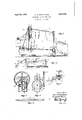
- Fig 1 is a side elevation of so much. of a plowas is herein involved.
- Fig. 1a is a modification of the differential v at a slightly increased rate which inordinary hoist shown in Fig. 1.
- Fig. 2 is a section through the drum g- Fig.4 a'fri gmentary view showing the wing slide and the universalwing bladeeonnection therewith, and
- the lateraladjustability has to beaccommodated and-this may or may not be simultaneous withthe vertical adjustability.
- this construction consists of a laterally adjustable and vertically movable strut which is pivotally' attached to the wing at its outer end and at its rear end is carried by a vertically movable block adjusted in the slideway on the H beam which constitutes the rear frame of the nose portion of: the plow.
- This provides for a vertically movable base support for the side strut in any position of the wing member so that wherever positioned this wing member may be backed up at any. desired angle by the strut member which at the same time permits independently of its own vertical adjustment, the ree movement of the wing member upwardly and inwardly of its arc of movement'as provided by the dili'erential adjustment before described.
- the adjustment is initially a Vela tical adjustment and in its secondary phase increasingly a lateral adjustment.
- the wing member comprises a slide 6 vertically adjustable on the column 4 and to thisslide is pivoted the wing proper or blade 7, the blade 7 being hinged to the slide 6 so as to swing for lateraladjustment as at 8 and also pivoted as at 9 so as tobe capable of being tipped at desired angle to the horizontal.
- the wing blade is backed up in any position of its adj ustment by a strut 10 which is pivotally connected to the free end of the wing blade at one of its ends and pivotally connected to a slide 11 at its other end.
- the slide 11 may be conveniently mounted on the column 3 on which it is vertically adjustable by a screwlZcontrolled by acrank or other suitable rotating means 13. e
- the slide 11 By rotating the screw 12 the slide 11 may be positioned at any elevation so that the rear end of the strut 10 can be set in such position as to afford a suitable bracing for the wing blade at whatever elevation, or at whatever lateral angle, or at Whatever position of tip to the horizontal it may be set.
- the wing then acts as a conveyor and carries to one side the snow plowed by the nose.
- the matter :of angularity is of great importance in widening work as it is necessary to move laterally banks plowed up by an original out. ,These become higher and higher as widening is repeated, or where driftshave to be'cle'ared out.
- wings sloped with the wing tip higher than the front end give less torsional strains on the truck or tractor, as by elevation these strains are applied less severely the outerend and give less leverage. This also forms a sloped bank with less of a vertical shelf'which does not hold .the transversely drifting snow.
- WVe accomplish this difi erential-aadjustt ment by-plural drum hoists one for theforward or pivoted end of the wing as a Whole, and the other for the free end 'ofthe wing blade
- These hoists are in the form shown a pair of wire cables '15 and 'l6 suita bly connected one to the wingsl idex6 -and the other to the blade 7.
- the cable 15 from the slide 6 is passed over a sheave 4 on the column 4: and led to a pulley'14 on the column 3.
- the cable 16 from the free end ofthe wingbla-de passes over a sheave 14 on the column 3.
- this consists of a pair of drums 17 and 18 connected. or preferably integraL,
- drum 1'? is of smaller diameter than 18 and to it is attached the front cable forraisumn 4.
- the cable '16 attached to the larger drum 18 preferably is taken up at about twice 7 the rate as is the front cable 15so that as the wing member as a whole is elevated, the rear end of its blade is increasingly elevated so as to give the blade an increasing pitch.
- the drums are adjusted by a worm 1 9 engaging a worm gear 20 connected to the drums so that the wing may be raised and held as desired.
- Fig. 1 the construction shown is illustrative and the several parts or 'fea tures while preferably combined to give the maximum range of adjustments heretofore in sub-combinations, although at alessened efficiency to meet general conditions;
- the differential wing. hoist before described may, of course, be effected in different ways, although that shown in Fig. 1 is preferred.
- We have indicated in Fig. 1a a difierential mg the wing member vertically on the 001- hoists at different rates.
- the drum 21 is turned the'cable 16a will be taken in twice as fast as will 15a so that the free end of the wing blade 7 will be" raised substantially twice asfast as will its forward-end attachedto the WIlIl slide 6..
- Such a rigging may further be e l theus'e of double andsingle pulleys.
- the two to'one'r'atio is generally found to-be'satisfactory, but maybe varied tocmeet-conditions; 1 To thisend the drum structureis of advantage iii-that drums of different pro portions may be substituted as desired.
- a wing member connected for vertical and lateral adjustment at one end to asupport, and having a free end,v
- a hoist for the connected end-and ahoist for the'free end of the'fwingmember and means u common to'both hoists forta k'ing up on said hoistsat diiferent rates.
- aframe including a vertical slideway, a slide thereon, a wing member pivotedto said slide and having a free end, a hoist for the slide and a hoist :for
- a verticallyadjustable pivoted blade having a free end, a hoist for raising the pivoted end ofthe blade vertically, a second hoist for raising the free end of the blade, and means commontogboth hoists for simultaneously taking up on said hois'tsat different rates whereby thefree end is increasingly elevated a'bovejthe pivoted end as the wing member is elevated.
- pivoted blade having a free end, a hoist for" raislngthe pivoted-end of the blade vertically, a second hoist for raising the free end of the blade, and means common to both'hoists for simultaneously taking up on sai'dhoists atdifi'erent'rates whereby the free end is increasingly elevated above the'pivoted end as the bladeiselevatedcomprising, a pair of differential; drums for the" two hoisting.
- -6 In a snow plow, a front and-a rear column, a slide on the fronticolumn, a Wing blade pivoted at one end to saidslide and having its other end free, a hoist for raising the wing slide vertically, a second hoist for raising the free end of'the blade, and means common to both hoists for simultanenously taking up on said hoists at different rates whereby the free end is increasingly elevated above the pivoted end as the blade is elevated.
- a front and a rear column aslide on the front column, a wing blade pivoted at one endto said slide and having its other end free, a hoist for raising the wing slide vertically, a second hoist for raising the free end of the blade, a pair of differential drums common to the two hoists, and means for rotatably adjusting said drums.
- a forward column and a rearward column In a snow plow, a forward column and a rearward column, a slide adjustable vertically'on said forward column, a wing having a pivotal and a hinged connection at its forward end to said slide and free at its rear end, a second slide adjustable vertically on said rearward column, a bracing strut interposed between said second slide and the rear end of said wing and pivotally connected at oneendto said second slide and at its opposite end to said wing, means for adjusting said second slide vertically, a hoist connected to the forward end of said wing and a hoist connected to the rear end of said wing,
- a forward column and V a rearward column, a slide adjustable verforward end to said slide and free at its rear end, a second slide adjustable vertically onsaid rearward column, a telescopic bracing strut interposed between said second slide and the rear end of said wing and pivotally connected at one end to said second slide and at its opposite end to said wing, a
- a hoist connected to the forward endof said wing and a hoistconnected to the rear end of said wing, and a commonoperating means for taking up on both of said hoists at different rates.
Landscapes
- Engineering & Computer Science (AREA)
- Architecture (AREA)
- Civil Engineering (AREA)
- Structural Engineering (AREA)
- Soil Working Implements (AREA)
Description
' April 12, 1932. G. c. SOULE ET AL ADJUSTABLE HOIST WING PLOW Filed Oct. 18, 1929 InvenZor-s.
w/bJ/NB- %0DBI1RY. GEmwE C .Soumz flfforny.
Patented Apr. 12, .1932
enonea 0. seats AND JOHN B. WOODBURY, or soon: PORTLAND,MAINE, AssmNons T MAINE swan; Pnonn'c'rs COMPANY, OF PORTLAND; MAINE, A, CORPORATION,
} OF MAINE "Application filed October is, 1929. Serial No. 400,546; If
Our present invention deals with wingv snow plows. In such plows it is desirable that the wing membersbe adjustable both laterally and "vertically and the problem has been to provide forrsuch adjustments with a maximum range of adjustability and with adequate strength at. the difierent positions of adjustment. a g 1 As illustrative of our inventionwe have shown a form in which a plow of general characteristic type is provided with a wing member. In this in accordance with-our invention there is provided a maximum of vertical adjustability with a corresponding range of lateraladjustability or width,- and at the same time with a provision for support 'in any one of the infinite number of positions .of adjustment in whichthe wing may be placed. t
As illustrative of such a structure we have shown in the accompanying drawings a plow having pivoted wingsprovided with means for adjustment and also in accordance with our invention with meansfor efiecting said V hoist.
adjustment in such a way that the front and rear end of such sections may be raised and lowered so that the rear end of thewing will be picked up or lowered more rapidly than the forward end of the wing so that in its disposition to the road such a wing may be maintained in a position of maximumefficiency. This, furthermore, is combined with the lateral means of maintenance which in the formshown is a lateral strut arm. Such a means while illustrated as a lateral strut arm may be otherwise constituted, but the form shown is simple and eflicient and is herein included as a desirable structure and so claimed, In the drawings;
Fig 1 is a side elevation of so much. of a plowas is herein involved.
Fig. 1a is a modification of the differential v at a slightly increased rate which inordinary hoist shown in Fig. 1.
Fig. 2 is a section through the drum g- Fig.4 a'fri gmentary view showing the wing slide and the universalwing bladeeonnection therewith, and
. Fig. 5 a d tail of the strut armff if i for the wing in its angle position so that in 9 means of which we are able to raise therear', V
3is a. side elevation of the" :1 f H ADJUSTABLE. Horse: w'INe rLow oF icE In the control of the side' wingsofthese plows the important requirement has been to produce a maximum variation in the width of spread of the plow laterally while at the adjustment ofthe plow wing in order tot'ake care of lateral shoulders or previous banks so that the snow picked up by the nose of the plow may be diverted at any desired level and delivered as farv to the side of the plowyas 14- same time providing for 'a'maximum verticalf o front and the rear of the wingswhich under ordinary conditionsis necessarilydifli'erentin degree. At the'same time the lateraladjustability has to beaccommodated and-this may or may not be simultaneous withthe vertical adjustability. This involves four features of adjustment, one as to spread, one as to} front end lift, one to-rear end lift, and one :toclose or collapse .the wing as in passing a'vehicle or an obstruction. v
To meet these separate requirements" we have contemplatedas two available factors,
first a differential lift for simultaneously han dling both the front and rear end of the wing, and secondly, a variantlyadjustable support" its different planes of vertical adjustment it maybe given theproperlateral adjustment T and support necessary to meet the, lateral factors encountered by the plow in working in the. widenranges beyond the ordinary;
courseo'f the-tractor. I v
To'this end we haveprovided a differential lift which will be hereinafter describedby end of the plow wing morerapidly than the front and this difierential being arranged in such proportion that the rear end willraise scribed, is also adjustable to provide a simultaneousand accommodating reinforcement we I and variable lateral c ontroloftheplow wings for the wing in any one of the various positions in which it may be adjusted by the vertical lift.
In the form shown this construction consists of a laterally adjustable and vertically movable strut which is pivotally' attached to the wing at its outer end and at its rear end is carried by a vertically movable block adjusted in the slideway on the H beam which constitutes the rear frame of the nose portion of: the plow. This provides for a vertically movable base support for the side strut in any position of the wing member so that wherever positioned this wing member may be backed up at any. desired angle by the strut member which at the same time permits independently of its own vertical adjustment, the ree movement of the wing member upwardly and inwardly of its arc of movement'as provided by the dili'erential adjustment before described. It will be noted that in this move ment which is potentially in an arc or" about 90 01": angle, the adjustment is initially a Vela tical adjustment and in its secondary phase increasingly a lateral adjustment.
This combines with the adj ustability of the strut by reason of which the center of swing may be raised so that the degree of vertical or lateral adju'stability as provided by the differential adjustment means may be changed or varied as desired so that the side arm may be positioned at any degree of angle and any degree of vertical adjustment to meet any plowing conditions that may be required.
In the drawings we have indicated a single wing of a plow which in the form shown is adapted to be used with a truck as distinguished from a tractor. It will'be understood that our invention is applicable to any type of wing plow and the truck type is merely selected for the purposes of illustration as beingrather more simple than those of tractor type. We have indicated at B in dotted lines the body of a truck T and across the body top are beams 1 and 2. At the end of the forward beam 2 is supported a column .3. There also provided for such construction a forward column l located adjacent the nose 5. The wing member comprises a slide 6 vertically adjustable on the column 4 and to thisslide is pivoted the wing proper or blade 7, the blade 7 being hinged to the slide 6 so as to swing for lateraladjustment as at 8 and also pivoted as at 9 so as tobe capable of being tipped at desired angle to the horizontal. The wing blade is backed up in any position of its adj ustment by a strut 10 which is pivotally connected to the free end of the wing blade at one of its ends and pivotally connected to a slide 11 at its other end. The slide 11 may be conveniently mounted on the column 3 on which it is vertically adjustable by a screwlZcontrolled by acrank or other suitable rotating means 13. e
By rotating the screw 12 the slide 11 may be positioned at any elevation so that the rear end of the strut 10 can be set in such position as to afford a suitable bracing for the wing blade at whatever elevation, or at whatever lateral angle, or at Whatever position of tip to the horizontal it may be set.
In order to provide for these various adjustments without necessity of stopping the plow and without interrupting the workand so that varying conditions along the road may be met as they occur, we provide for a take-up. As heretofore pointed out it is desirable that the wing blade be increasingly inclined to the road in its successive vertical adjustments. There are two principal phases of the work who done. One of these is where the depth of the snow permits the truck or tractor to scrape a widesurface all the-way to the tip of the wing. in this :position the Wing wedgeis close-to the roadandhorizontal. As the snow becomes heavy and pro pulsion insufiicient to overcome such resist ance, it is necessary to raise the wing and let'the nose do the plowing. The wing then acts as a conveyor and carries to one side the snow plowed by the nose. The matter :of angularity is of great importance in widening work as it is necessary to move laterally banks plowed up by an original out. ,These become higher and higher as widening is repeated, or where driftshave to be'cle'ared out. In this work wings sloped with the wing tip higher than the front end give less torsional strains on the truck or tractor, as by elevation these strains are applied less severely the outerend and give less leverage. This also forms a sloped bank with less of a vertical shelf'which does not hold .the transversely drifting snow.
From the foregoing reasons itwillzbe seen that there is a great advantage in having a wing adjustment which provides that the wing be parallel to the ground in its lowest position and increasingly pitched up it is raised to higher levels. It is also important, as herein provided, that in meeting traffic or obstacles that it be possible to close in the wings entirely to a collapsed position. Due to-the effect ofwind and other disturbances di-flerentconditions are met with in rapidsuccession on almost. any road plowing job. The adjustments must therefore he made quickly and easily in lorder to :save
time and expense. This we accomplish .sim-
ply but effectively by our differential. hoist and mounting and all' eftectively braced by the adjustment of the strut rods.
WVe accomplish this difi erential-aadjustt ment by-plural drum hoists one for theforward or pivoted end of the wing as a Whole, and the other for the free end 'ofthe wing blade These hoists are in the form shown a pair of wire cables '15 and 'l6 suita bly connected one to the wingsl idex6 -and the other to the blade 7. The cable 15 from the slide 6 is passed over a sheave 4 on the column 4: and led to a pulley'14 on the column 3. The cable 16 from the free end ofthe wingbla-de passes over a sheave 14 on the column 3. e
To operate these cables simultaneously but to take up on them at different rates, we provide a differential take-up. In the form shown this consists of a pair of drums 17 and 18 connected. or preferably integraL, The
drum 1'? is of smaller diameter than 18 and to it is attached the front cable forraisumn 4. The cable '16 attached to the larger drum 18 preferably is taken up at about twice 7 the rate as is the front cable 15so that as the wing member as a whole is elevated, the rear end of its blade is increasingly elevated so as to give the blade an increasing pitch. The drums are adjusted by a worm 1 9 engaging a worm gear 20 connected to the drums so that the wing may be raised and held as desired.
In these various positions of adjustment the strut 10 being. pivoted to the blade 7 and the slide 11 is rocked to accommodate any.
such movement. In so doing it has a potential movement of about 90 are. As before mentioned this are considered from the hori-' zontal first has a maximum component of vertical rise, and in its movement towards the vertical has a maximum movement horizontally towards the truck. c I
This therefore introduces two guiding factorsin addition to the pull of the hoist particularly in the free end of the wing blade,
the tendency of course being to narrow the Y spread of the wing as it rises. The strut 10,
l described, may, of course, be used singly or however, being vertically adjustable on the column 8 through its slide 11 maybe given any vertical position at its rear end. This affords an additional factor of adjustment and very importantly provides for the posi-.
As before suggested, the construction shown is illustrative and the several parts or 'fea tures while preferably combined to give the maximum range of adjustments heretofore in sub-combinations, although at alessened efficiency to meet general conditions; The differential wing. hoist before described may, of course, be effected in different ways, although that shown in Fig. 1 is preferred. We have indicated in Fig. 1a a difierential mg the wing member vertically on the 001- hoists at different rates.
hoist in which the forward hoist cable for raising the slide 6 is indicat'ed at 15a passing over a sheave l'aand thence tothe slide 6.
The-rear'end hoist 16a'passe's about asheave 14a being anchored at 3a. The sheave 140-is attached to a cable 14?) which is spliced to the cable 15a which is passed to a single drum 21. When the drum 21 is turned the'cable 16a will be taken in twice as fast as will 15a so that the free end of the wing blade 7 will be" raised substantially twice asfast as will its forward-end attachedto the WIlIl slide 6..
iIected Such a rigging may further be e l theus'e of double andsingle pulleys. I The two to'one'r'atio is generally found to-be'satisfactory, but maybe varied tocmeet-conditions; 1 To thisend the drum structureis of advantage iii-that drums of different pro portions may be substituted as desired.
All such modifications ofhoist, as well as details of structure are to beunderstood as within our concept within the limits of the appended claims.
-wethereforeclaim and desire togse cure by LettersPatent is: 1
-' 1. In a snow plow, a wing member connected for vertical and lateral adjustment at one end to asupport, and having a free end,v
a hoist for the connected end-and ahoist for the'free end of the'fwingmember, and means u common to'both hoists forta k'ing up on said hoistsat diiferent rates.
In a snow plow, aframe "including a vertical slideway, a slide thereon, a wing member pivotedto said slide and having a free end,a hoist for the slide and a hoist :for
the free end of the wing memben and means 1 common to both ho1sts for taking up on said 3. In a snow plow, a verticallyadjustable pivoted blade having a free end, a hoist for raising the pivoted end ofthe blade vertically, a second hoist for raising the free end of the blade, and means commontogboth hoists for simultaneously taking up on said hois'tsat different rates whereby thefree end is increasingly elevated a'bovejthe pivoted end as the wing member is elevated.
4'. In a snow plow,'a vertically adjustable pivoted blade having a free end, a hoist for raising the pivoted endof the blade-vertia 'cally," a second hoist for raising'the.free'end of the @blade, a pair of diiferential drums common to the two hoists and means for ro tatably adjusting said drums.-
pivoted blade having a free end, a hoist for" raislngthe pivoted-end of the blade vertically, a second hoist for raising the free end of the blade, and means common to both'hoists for simultaneously taking up on sai'dhoists atdifi'erent'rates whereby the free end is increasingly elevated above the'pivoted end as the bladeiselevatedcomprising, a pair of differential; drums for the" two hoisting.
I I 5. In asnow plow, a vertically adjustable tically on said forward column, a wing having a pivotal and a hinged connection at its cables, a gear on saiddrumsand a worm drive for rotatably adjusting said drums.
-6, In a snow plow, a front and-a rear column, a slide on the fronticolumn, a Wing blade pivoted at one end to saidslide and having its other end free, a hoist for raising the wing slide vertically, a second hoist for raising the free end of'the blade, and means common to both hoists for simultanenously taking up on said hoists at different rates whereby the free end is increasingly elevated above the pivoted end as the blade is elevated.
7. In a snow plow, a front and a rear column, aslide on the front column, a wing blade pivoted at one endto said slide and having its other end free, a hoist for raising the wing slide vertically, a second hoist for raising the free end of the blade, a pair of differential drums common to the two hoists, and means for rotatably adjusting said drums. 8. In a snow plow, a forward column and a rearward column, a slide adjustable vertically'on said forward column, a wing having a pivotal and a hinged connection at its forward end to said slide and free at its rear end, a second slide adjustable vertically on said rearward column, a bracing strut interposed between said second slide and the rear end of said wing and pivotally connected at oneendto said second slide and at its opposite end to said wing, means for adjusting said second slide vertically, a hoist connected to the forward end of said wing and a hoist connected to the rear end of said wing,
and a common operating means for taking up on both of sald hoists at dlfi'erent rates.
9. In a snow plow, a forward column and V a rearward column, a slide adjustable verforward end to said slide and free at its rear end, a second slide adjustable vertically onsaid rearward column, a telescopic bracing strut interposed between said second slide and the rear end of said wing and pivotally connected at one end to said second slide and at its opposite end to said wing, a
screw having a crank for adjusting said sec-.
ond slide vertically, a hoist connected to the forward endof said wing and a hoistconnected to the rear end of said wing, and a commonoperating means for taking up on both of said hoists at different rates.
In testimony whereof we affix our signatures.
GEORGE C. SOULE.
JOHN B. WOODBURY.
Priority Applications (1)
| Application Number | Priority Date | Filing Date | Title |
|---|---|---|---|
| US400546A US1853939A (en) | 1929-10-18 | 1929-10-18 | Adjustable hoist wing plow |
Applications Claiming Priority (1)
| Application Number | Priority Date | Filing Date | Title |
|---|---|---|---|
| US400546A US1853939A (en) | 1929-10-18 | 1929-10-18 | Adjustable hoist wing plow |
Publications (1)
| Publication Number | Publication Date |
|---|---|
| US1853939A true US1853939A (en) | 1932-04-12 |
Family
ID=23584035
Family Applications (1)
| Application Number | Title | Priority Date | Filing Date |
|---|---|---|---|
| US400546A Expired - Lifetime US1853939A (en) | 1929-10-18 | 1929-10-18 | Adjustable hoist wing plow |
Country Status (1)
| Country | Link |
|---|---|
| US (1) | US1853939A (en) |
Cited By (5)
| Publication number | Priority date | Publication date | Assignee | Title |
|---|---|---|---|---|
| US2524329A (en) * | 1949-02-07 | 1950-10-03 | Walter B Richardson | Hydraulic wing control |
| US6581307B1 (en) * | 2002-07-29 | 2003-06-24 | Burke Truck & Equipment, Inc. | Wing plow assembly |
| US20140196322A1 (en) * | 2012-09-04 | 2014-07-17 | Universal Truck Equipment, Inc. | Wing plow post |
| US9085860B2 (en) | 2012-09-04 | 2015-07-21 | Universal Truck Equipment, Inc. | Wing plow post |
| US10053826B1 (en) | 2014-12-12 | 2018-08-21 | Alamo Group Inc. | Wing plow apparatus |
-
1929
- 1929-10-18 US US400546A patent/US1853939A/en not_active Expired - Lifetime
Cited By (8)
| Publication number | Priority date | Publication date | Assignee | Title |
|---|---|---|---|---|
| US2524329A (en) * | 1949-02-07 | 1950-10-03 | Walter B Richardson | Hydraulic wing control |
| US6581307B1 (en) * | 2002-07-29 | 2003-06-24 | Burke Truck & Equipment, Inc. | Wing plow assembly |
| US20140196322A1 (en) * | 2012-09-04 | 2014-07-17 | Universal Truck Equipment, Inc. | Wing plow post |
| US9085860B2 (en) | 2012-09-04 | 2015-07-21 | Universal Truck Equipment, Inc. | Wing plow post |
| US9752293B2 (en) * | 2012-09-04 | 2017-09-05 | Universal Truck Equipment, Inc. | Wing plow post |
| US10053826B1 (en) | 2014-12-12 | 2018-08-21 | Alamo Group Inc. | Wing plow apparatus |
| US10196790B1 (en) | 2014-12-12 | 2019-02-05 | Alamo Group Inc. | Wing plow apparatus |
| US10480141B1 (en) | 2014-12-12 | 2019-11-19 | Alamo Group Inc. | Wing plow apparatus |
Similar Documents
| Publication | Publication Date | Title |
|---|---|---|
| US2309750A (en) | Earth mover | |
| US3822751A (en) | Mounting assembly for attaching a material treating blade to a vehicle | |
| US2057326A (en) | Snow plow | |
| US1853939A (en) | Adjustable hoist wing plow | |
| US2787847A (en) | Scraper attachment for tractors | |
| US2643472A (en) | Bulldozer | |
| US1943196A (en) | Attachment for tractor cranes | |
| US2274904A (en) | Trail builder attachment for tractors | |
| US2547680A (en) | Ditch grader | |
| US2138783A (en) | Snow plow | |
| US2243306A (en) | Power control for earth working devices | |
| US1537412A (en) | Machine for cutting sod | |
| US2505202A (en) | Self-powered scraper | |
| US2302335A (en) | Carrying scraper | |
| US2650441A (en) | Land leveling machine | |
| US1918169A (en) | Road grader and scarifier | |
| US1759982A (en) | Hydraulically-controlled leveler | |
| US2285550A (en) | Disk control and draft unit | |
| US1858212A (en) | Snowplow | |
| US1701746A (en) | Snowplow | |
| US2564567A (en) | Universal self-contained plow | |
| US2536405A (en) | Land leveler with coordinated wheel adjustment means | |
| US2417520A (en) | Bulldozer | |
| US1509189A (en) | Drag | |
| US2189286A (en) | Road machine |