US1853937A - Piston ring - Google Patents
Piston ring Download PDFInfo
- Publication number
- US1853937A US1853937A US492549A US49254930A US1853937A US 1853937 A US1853937 A US 1853937A US 492549 A US492549 A US 492549A US 49254930 A US49254930 A US 49254930A US 1853937 A US1853937 A US 1853937A
- Authority
- US
- United States
- Prior art keywords
- ring
- groove
- edge
- piston
- cylinder
- Prior art date
- Legal status (The legal status is an assumption and is not a legal conclusion. Google has not performed a legal analysis and makes no representation as to the accuracy of the status listed.)
- Expired - Lifetime
Links
Images
Classifications
-
- F—MECHANICAL ENGINEERING; LIGHTING; HEATING; WEAPONS; BLASTING
- F16—ENGINEERING ELEMENTS AND UNITS; GENERAL MEASURES FOR PRODUCING AND MAINTAINING EFFECTIVE FUNCTIONING OF MACHINES OR INSTALLATIONS; THERMAL INSULATION IN GENERAL
- F16J—PISTONS; CYLINDERS; SEALINGS
- F16J9/00—Piston-rings, e.g. non-metallic piston-rings, seats therefor; Ring sealings of similar construction
- F16J9/12—Details
- F16J9/20—Rings with special cross-section; Oil-scraping rings
- F16J9/203—Oil-scraping rings
-
- F—MECHANICAL ENGINEERING; LIGHTING; HEATING; WEAPONS; BLASTING
- F16—ENGINEERING ELEMENTS AND UNITS; GENERAL MEASURES FOR PRODUCING AND MAINTAINING EFFECTIVE FUNCTIONING OF MACHINES OR INSTALLATIONS; THERMAL INSULATION IN GENERAL
- F16J—PISTONS; CYLINDERS; SEALINGS
- F16J9/00—Piston-rings, e.g. non-metallic piston-rings, seats therefor; Ring sealings of similar construction
- F16J9/06—Piston-rings, e.g. non-metallic piston-rings, seats therefor; Ring sealings of similar construction using separate springs or elastic elements expanding the rings; Springs therefor ; Expansion by wedging
- F16J9/061—Piston-rings, e.g. non-metallic piston-rings, seats therefor; Ring sealings of similar construction using separate springs or elastic elements expanding the rings; Springs therefor ; Expansion by wedging using metallic coiled or blade springs
- F16J9/063—Strip or wire along the entire circumference
Definitions
- Rings of this type have heretofore been used as replacement rings but difliculty has been experienced in the mounting of the rings on the piston and the engagement of the same with the cylinders. This is due to the fact that with shal low ring grooves the tension of the expander when engaged therewith may expand the inner face of the ring beyond the circumference of the piston. There is therefore danger that in entering the rings in the cylinder they may overlap and catch on one edge of the ring groove so as to be broken. Particularly where one land of the ring groove has been relieved as at the bottom of the piston, there is danger of this result.
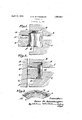
- Figure 1 is an enlarged cross sectional view through the ring as it is being engaged with the ring groove of a piston
- Figure 2 is a similar view showing the ring in full engagement with the groove and the piston and ring in engagement with the cylin- Figure 3 is a horizontal section through a portion of the piston, cylinder and ring.
- My improved ring consists essentially in a construction which is restricted in radial depth to give the desired flexibility and also to adapt it for use in ring grooves of minimum radial depth.
- the necessary radial tension is supplied by an expander preferably formed of a corrugated ribbon of steel having contact points distributed around the circumference to conform the flexible ring to the cylinder wall. To insure registration of the ring with the ring grooves even where the latter are quite shallow, the upper edge of the ring or side towards the combustion.
- the chamber is provided with a radially inwardly extending lip or flange of suflicient depth to be certain to enter the groove.
- the expander is less in width than the ring groove by an amount approximately the same as the thickness of this lip or flange, one edge of said expander enga lip and the other e ge engaging the opposite face of the groove.
- A is the ring of a width'correspending to that of the ring groove B in the piston C.
- the body portion of the ring is restricted in radial depth so as to render the same quite flexible but at the upper edge or side towards the combustion chamber there is the inwardly extending lip or flange D of suflicient extent to insure engagement with the groove.
- E is a corrugated ribbon expander of a width less than the width of the ring A and such that when placed with one enter't e bined width of the expanderand the lip is slightlfy less than the width of the groove so 1 as to same.
- the ringland expander may be readilien aged with t e groove in the pisel in registration even where the of the ring does not initially enter
- the ring is contract ed by the use of any suitable ring clam there is not the slightest danger that it w' catch on' the edge of the groove as would be likely if not positively held in registration.
- the expander fail exactly register the ring, the chamfer w1ll guide it into the. groove.
- the ring is preferably erentially extending slots H which permit flow of the oil between the cylinder wall and the ring groove.
- the oil thus admitted to the groove will flow over the top of the expander which is less in width than the ring groove and will Also where the peripheral face is ta rs inward from the lower edge G at P slots and will prevent into the explosion chain It is qlntc common factors of pistons to adjacent to the lower ractice in the manuringv groove so as to senses the diameter leave ater clearance between the same and the cy inder wall as indicated at J, Figure 2.
- upper and ower sides as appli to the ring and'ring groove I mean the sides respectively towards or away from the combustion chamber even should the engine be reversed in position.
- What I claim as my invention is: 1. The combination with a cylinder and a piston having a ring groove therein, of a rmgm tion of said in radial said groove provided with a series .of circumferential slots extending thereis prevented by the a mo. worn to form a thickness to increase the flexibility thereof, leaving a radially inwardly extending lip or flange adjacent to its upper edge only, an the peripheral portion of said ring being slightly tapered radially inward from the lower edge portion upward, and an expander of lesser width than the ring engaging the same to press the projecting edge of the tapered periphery against the cylinder.
Description
April 2- D. M. SOLENBERGER 1,853,937
' PISTON RING Filed Oct. 31, 1930 Inventor.- Dean Jiibj'alenberg Patented Apr. 12, 1932 UNITED STATES PATENT OFFICE DEAN I. SOLENBEBGEB, OF CLEVELAND, OHIO, ABSIGNOB 1'0 mm mm: IMO! RING COMPANY OF AMERICA, INC, A CORPORATION OF OHIO PISTON R11! G Application filed October 81, 1980. Serial In. 493,548.
In the present state of the art there is no standard depth for the ring grooves of pistons used in internal combustion engines, these frequently varying from one-eighth to three-sixteenths in radial depth where the 1 width or axial dimension is the same. It is also customary to decrease the diameter of the piston below the lowermost groove so as to give an increased clearance between the same and the cylinder wall. Where, as is frequently the case, the cylinder is warped, distorted or worn so as not to be of true circular form, an ordinary piston ring will not conform thereto to make a tight seal. However, a ring which is restricted in radial depth to be more flexible and which is backed by an expander having contacts distributed around the circumference thereof ma be held in close contact with the cylinder wall. Rings of this type have heretofore been used as replacement rings but difliculty has been experienced in the mounting of the rings on the piston and the engagement of the same with the cylinders. This is due to the fact that with shal low ring grooves the tension of the expander when engaged therewith may expand the inner face of the ring beyond the circumference of the piston. There is therefore danger that in entering the rings in the cylinder they may overlap and catch on one edge of the ring groove so as to be broken. Particularly where one land of the ring groove has been relieved as at the bottom of the piston, there is danger of this result.
With my improved construction I avoid the difficulties above referred to and at the same time obtain a high eificiency both in sealing for pressure and in preventing oil pumping.
In the drawings:
Figure 1 is an enlarged cross sectional view through the ring as it is being engaged with the ring groove of a piston;
Figure 2 is a similar view showing the ring in full engagement with the groove and the piston and ring in engagement with the cylin- Figure 3 is a horizontal section through a portion of the piston, cylinder and ring.
My improved ring consists essentially in a construction which is restricted in radial depth to give the desired flexibility and also to adapt it for use in ring grooves of minimum radial depth. The necessary radial tension is supplied by an expander preferably formed of a corrugated ribbon of steel having contact points distributed around the circumference to conform the flexible ring to the cylinder wall. To insure registration of the ring with the ring grooves even where the latter are quite shallow, the upper edge of the ring or side towards the combustion.
chamber is provided with a radially inwardly extending lip or flange of suflicient depth to be certain to enter the groove. The expander is less in width than the ring groove by an amount approximately the same as the thickness of this lip or flange, one edge of said expander enga lip and the other e ge engaging the opposite face of the groove. Thus even where the groove is so shallow that the thin portion of the ring will not enter the same before the contraction of the ring, and where the pisg the inner face of the ton has been greatly relieved or reduced in diameter adjacent to the groove on the side opposite to that engaged by the lip, the expander will hold said ring in registration with the groove and will therefore prevent danger of breakage.
In detail, A is the ring of a width'correspending to that of the ring groove B in the piston C. The body portion of the ring is restricted in radial depth so as to render the same quite flexible but at the upper edge or side towards the combustion chamber there is the inwardly extending lip or flange D of suflicient extent to insure engagement with the groove. E is a corrugated ribbon expander of a width less than the width of the ring A and such that when placed with one enter't e bined width of the expanderand the lip is slightlfy less than the width of the groove so 1 as to same.
mama-11d.
catching the inner edge 0 go F, so that even s rm a working engagement with the with the constructionas thus far described, it is obvious that the ringland expander may be readilien aged with t e groove in the pisel in registration even where the of the ring does not initially enter Thus when the ring is contract ed by the use of any suitable ring clam there is not the slightest danger that it w' catch on' the edge of the groove as would be likely if not positively held in registration. However, to eliminate any ossibillty of such the thin portion of the ring is slightl chamfered as indicated at hould the expander fail exactly register the ring, the chamfer w1ll guide it into the. groove.
When rings are first engaged with cylinders it is seldom possible to orm a sealing thin edge the groove.
' hearing around the entire circumference as there are generally slight irregularities either in the cylinder or in the ring which form noncontactmg areas. However, after the ring has been in service for a certain length of time it will become conformed to the cylinder tions only.
angle to the top two and one-half or three drgrees,
all so as to form an effective seal. To ex- 1 'te this result I form the outer peripheral surface of' the ring non-parallel to the axis of the cylinder with its maximum diameter 35 at its lower edge.'
This tapering of the surly not to exceed but it is suflicient to restrict the initial contact of the ring with the cylinder to the lower edge por- Consequently the ring W111 rapidly wear on these contacting portions until face isvery shght, prefera full sealing contact is obtained around the entire circumference. Eventually the wear may extend further up the length of the taper 45 to become parallel to the cylinder wall. .Thus
as shown 1n Figure 2 the perlphery of the ring ta an ang e of approximately two and one-half degrees to a point G and then at a greater of the ring. In wearing in the ring will (gradually extend its bearing surface u war for a portion of the distance between t e points G and G to become parallel to the cylinder wall, but the total area of contact will be less than the full width of the provided with a series of circum which will reducethe' unit pressure required for maintaining the required pressure on the oil film.
As has been stated, the ring is preferably erentially extending slots H which permit flow of the oil between the cylinder wall and the ring groove. The oil thus admitted to the groove will flow over the top of the expander which is less in width than the ring groove and will Also where the peripheral face is ta rs inward from the lower edge G at P slots and will prevent into the explosion chain It is qlntc common factors of pistons to adjacent to the lower ractice in the manuringv groove so as to senses the diameter leave ater clearance between the same and the cy inder wall as indicated at J, Figure 2.
As this decreases the width of the land against which the lower edge of the ring contacts, it is desirable'to place the lip D at the top of the ringias has been describlegi the outwardly prqectmg edge should located at the bottom of e r1ng. To insure the installation of the rings right side up I preferably form a chamfer or bevel Kat the top ofthe peripheral face this being of a much steeper angle than t e taper between the points Gand G so that it can be readily observed by ,the workman. This beveled edge has the further advantage of reducing the width of the peripheral portion of the ring which eventually bears against the oil film and thus increases the unit pressure for use as an oil ring. It is, however, equally adapted for use as acompression ring, ut where so used the, peripheral surface is not initially tapered but is parallel to the axis of the ring and the cylinder. In use, after the ring has complete line of bearing around the circumference of the cylinder, the lower rtion of the periphery will thin the oil to the desired minimum. However, as some leakage of the oil past the oil ring is inevitable, this will tend to work upwar ,past the succesive rings until it enters the combustion chamber. Such a result slots H to that with the increased clearance between ripheral surface and the linder wall, and also by the pressure le l sage past the upper rings. us any accumulation of oil on the cylinder wall above the point G on the ring will be blown out by gas leakage through the slots H to the drain rt I.
In usin the terms upper and ower sides as appli to the ring and'ring groove I mean the sides respectively towards or away from the combustion chamber even should the engine be reversed in position.
What I claim as my invention is: 1. The combination with a cylinder and a piston having a ring groove therein, of a rmgm tion of said in radial said groove provided with a series .of circumferential slots extending thereis prevented by the a mo. worn to form a thickness to increase the flexibility thereof, leaving a radially inwardly extending lip or flange adjacent to its upper edge only, an the peripheral portion of said ring being slightly tapered radially inward from the lower edge portion upward, and an expander of lesser width than the ring engaging the same to press the projecting edge of the tapered periphery against the cylinder.
2. The combination with a cylinder and a piston having a ring groove therein, of a ring in said groove having its peripheral face tapered radially inward from its lower edge upward, said ring having its lower portion reduced in radial thickness to increase the flexibility thereof, leaving a radially inwardly extending lip or flange adjacent to its upper edge with oil apertures through the ring between its upper and lower edge and a corrugated ribbon expander of lesser width than the ring arranged beneath said inwardly projecting lip or flange and exerting radially outward pressure through the projecting edge of the tapered periphery against the oil film.
3. The combination with a piston having a ring groove therein, with a relieved portion beneath said groove reducing the width of the land for the ring, a ring having a series of circumferentially extending slots between its upper and lower faces, said ring being reduced in radial depth to increase the flexibility thereof and leave a radially inwardly extending lip or flange adjacent to the upper edge only, a corrugated ribbon expander of lesser width than the groove and engaging the same and bearing on said ring beneath said lip or flange one edge of the outer crest engaging said lip or flange, thereby holding said ring in registration with said groove for entrance therein, the inner lower edge of said ring being chamfered to facilitate entrance into said groove.
4. The combination with a piston having a ring groove therein and an adjacent peripheral portion reduced in diameter to form an oil channel partly cutting away one side wall of said groove, of a ring in said groove having its body portion reduced in radial thickness to increase flexibility and having an inwardly extending lip or flange adjacent to the wall of said groove opposite to the one partly cut away, and a corrugated ribbon expander having one edge of its outer crest engaging said' lip or flange and the opposite edge of the inner crest engaging said cut away wall of the groove to hold said ring in substantial registration with the groove.
5. The combination with a piston having a ring groove therein and an adjacent periph eral portion reduced in diameter to form an ,oil channel partly cutting away one side wall of said groove, of a ring in said groove having its body portion reduced 1n radial thlckness to increase flexibility and leaving an m ill wardly extending lip or flange adjacent to the wall of said groove opposite to the one partly cut-away, the opposite edge of said body or- In testimony whereof I aifix my signature.
DEAN M. SOLENBERGER.
Priority Applications (1)
| Application Number | Priority Date | Filing Date | Title |
|---|---|---|---|
| US492549A US1853937A (en) | 1930-10-31 | 1930-10-31 | Piston ring |
Applications Claiming Priority (1)
| Application Number | Priority Date | Filing Date | Title |
|---|---|---|---|
| US492549A US1853937A (en) | 1930-10-31 | 1930-10-31 | Piston ring |
Publications (1)
| Publication Number | Publication Date |
|---|---|
| US1853937A true US1853937A (en) | 1932-04-12 |
Family
ID=23956703
Family Applications (1)
| Application Number | Title | Priority Date | Filing Date |
|---|---|---|---|
| US492549A Expired - Lifetime US1853937A (en) | 1930-10-31 | 1930-10-31 | Piston ring |
Country Status (1)
| Country | Link |
|---|---|
| US (1) | US1853937A (en) |
Cited By (3)
| Publication number | Priority date | Publication date | Assignee | Title |
|---|---|---|---|---|
| US2912292A (en) * | 1956-12-19 | 1959-11-10 | Kloeckner Humboldt Deutz Ag | Oil control ring |
| US4422649A (en) * | 1982-03-02 | 1983-12-27 | Mechanical Technology Incorporated | Stirling engine piston ring |
| US5188375A (en) * | 1991-02-19 | 1993-02-23 | General Electric Company | Squeeze film damper piston ring seal |
-
1930
- 1930-10-31 US US492549A patent/US1853937A/en not_active Expired - Lifetime
Cited By (3)
| Publication number | Priority date | Publication date | Assignee | Title |
|---|---|---|---|---|
| US2912292A (en) * | 1956-12-19 | 1959-11-10 | Kloeckner Humboldt Deutz Ag | Oil control ring |
| US4422649A (en) * | 1982-03-02 | 1983-12-27 | Mechanical Technology Incorporated | Stirling engine piston ring |
| US5188375A (en) * | 1991-02-19 | 1993-02-23 | General Electric Company | Squeeze film damper piston ring seal |
Similar Documents
| Publication | Publication Date | Title |
|---|---|---|
| US1853937A (en) | Piston ring | |
| US2108392A (en) | Cylinder liner for internal-combustion engines | |
| US2213452A (en) | Piston ring | |
| GB1584087A (en) | Piston | |
| US2202802A (en) | Piston ring | |
| US1368447A (en) | Wiper-ring for the cylinders of internal-combustion engines | |
| US9334959B2 (en) | Radially notched piston rings | |
| GB2104621A (en) | Piston ring lubrication | |
| US1999494A (en) | Piston ring | |
| US2052077A (en) | Piston ring and assembly therefor | |
| US1856271A (en) | Piston ring | |
| US2334273A (en) | Piston ring | |
| US1360498A (en) | Piston-ring | |
| US1354548A (en) | Piston-ring | |
| US2179670A (en) | Piston ring | |
| US1658440A (en) | Piston packing | |
| US1356461A (en) | Packing-ring | |
| US1883637A (en) | Piston for internal combustion engines | |
| US1705648A (en) | Piston ring | |
| US1773749A (en) | Piston ring | |
| US1483352A (en) | Automatic cylinder ring | |
| US2311557A (en) | Piston ring | |
| US1586459A (en) | Piston ring | |
| US1802566A (en) | Piston ring | |
| US2234159A (en) | Piston ring |