US1853934A - Crossing gate - Google Patents
Crossing gate Download PDFInfo
- Publication number
- US1853934A US1853934A US498798A US49879830A US1853934A US 1853934 A US1853934 A US 1853934A US 498798 A US498798 A US 498798A US 49879830 A US49879830 A US 49879830A US 1853934 A US1853934 A US 1853934A
- Authority
- US
- United States
- Prior art keywords
- gate
- platform
- crossing
- train
- levers
- Prior art date
- Legal status (The legal status is an assumption and is not a legal conclusion. Google has not performed a legal analysis and makes no representation as to the accuracy of the status listed.)
- Expired - Lifetime
Links
- 230000004888 barrier function Effects 0.000 description 7
- 238000013459 approach Methods 0.000 description 2
- 238000010276 construction Methods 0.000 description 2
- 241000838698 Togo Species 0.000 description 1
- 230000000712 assembly Effects 0.000 description 1
- 238000000429 assembly Methods 0.000 description 1
Images

Classifications
-
- B—PERFORMING OPERATIONS; TRANSPORTING
- B61—RAILWAYS
- B61L—GUIDING RAILWAY TRAFFIC; ENSURING THE SAFETY OF RAILWAY TRAFFIC
- B61L29/00—Safety means for rail/road crossing traffic
- B61L29/02—Guards or obstacles for preventing access to the route
- B61L29/023—Special gates
- B61L29/026—Preventing access by means of obstacles raising across the route
-
- E—FIXED CONSTRUCTIONS
- E01—CONSTRUCTION OF ROADS, RAILWAYS, OR BRIDGES
- E01F—ADDITIONAL WORK, SUCH AS EQUIPPING ROADS OR THE CONSTRUCTION OF PLATFORMS, HELICOPTER LANDING STAGES, SIGNS, SNOW FENCES, OR THE LIKE
- E01F13/00—Arrangements for obstructing or restricting traffic, e.g. gates, barricades ; Preventing passage of vehicles of selected category or dimensions
- E01F13/04—Arrangements for obstructing or restricting traffic, e.g. gates, barricades ; Preventing passage of vehicles of selected category or dimensions movable to allow or prevent passage
- E01F13/048—Arrangements for obstructing or restricting traffic, e.g. gates, barricades ; Preventing passage of vehicles of selected category or dimensions movable to allow or prevent passage with obstructing members moving in a translatory motion, e.g. vertical lift barriers, sliding gates
Definitions
- Figure 2 is a section on line 22 of Figure 3. i
- Figure 3 is a section on the line 33 of Figure 1.
- Figure 4 is a detailed sectional view of on of the roller supporting posts.
- Figure 5 is a section on line 55 of Figure 3.
- the a pit extending acrossthe highway at each side of the track and the numeral 2' indicates a platform covering the pit and having vertical movement so that the platform will be lowered when a vehiclepasses from the high ⁇ way onto the same.
- the walls of the pit are formed with shoulders 3 to limit the down,- ward movement of the platform.
- a barrier or gate 4 passes through a slot 5 extending transversely inthe platform.
- a pair of posts 6 is located'in the pit adjacent each side thereof, the posts of each pair being connected together by a cross piece7.
- The'upper ends of the posts are formed with the slots numeral 1 indicates 8 for receiving the pintl-es of the spring roll- 1 ers 9', it being understood that a roller is supported by each pair ofposts.
- each roller is fastened in a bracket 10 carried by the cross piece 7 and the ends of the .housing are closed 'by the rotary caps 11- which carry the pintles.
- a shaft 12 passes through the housing and is connectedto' the caps.
- the springs 13 are carried bythe shaft, the outer ends of the springs being attached to the caps and their inner ends are fastened to a stationary part so that when the springs are wound they will actto turn the caps.
- a pair of weightedlevers 14 islocated in the pit and each lever is formed with a yoke shaped outer end, the limbs of which I are connected to the caps by having square openings therein through which square parts are slotted, as at" 16 to' receive a bar 16 which ways' if desired.
- a pair of tubular members 20 is attached 'tothe bottom of the platformat each side of
- the weights 15 v r are carried by'the outerends of the limbs of the levers;
- Theinner ends of the levers the barrier and a rod21 has its upper end engaging each member, the lower end of the rod being forked and connected to; a limb of a lever.
- a pair of links .22 is connected to each tubular memberand: each link has "its upper end fittingin a recess in a-flange formed; on the lower end of the tubular memher.
- a second pair of links 23' is pivoted 'to the lower ends of the first pair and the in the pit, eachpair beingarranged adjacent each link assembly with the rollers 26 e at the upper ends of the posts engaging the outeredges of the pair of lower links23. 1
- a latch 27 is provided for locking the gate in, raised position and this latch isoperated by atrain approaching the crossingv through means of the magnet 28- the circuit 29 of which. is closed by said train. After the train. passes the crossing the circuit is broken and the latch returns to inoperative. position. Thus. the gate cannot be lowered by a vehicle running; onthe-platform when a train is: approaching the crossing.
- the gate has on its front. facethe Words Ride onthe platform? so as to inform driversof. vehicles that they must ride on .the platform in order to lower: the gate and I also provide Stop and Go signals to notify. the drivers when togo ahead and when tostopr.
- alstationary plate 30 attached tothe gateiand enclosed by a casing 31 having a window therein through which one set or the other of. the signal wordsa-re visible.
- This-casing is movably arranged on the gate and it is It is thought from the foregoing description that the advantages and novel features of the invention will be readily apparent.
- a device of the class described comprising a centrally slotted vertically movable platform, a Vertically movable gate passing through the slot inthe platform, weighted swinging levers located under the platform andhavi'ng pin and slot connections with the gate, spring meanscoacting with the swinging, connections of the levers for normally holding the latter in a position wi-thtthe gate raised,.toggles oonnectingthe platform with the-levers, means-active onthe.
- toggleswhere- .by the platform Will be normally held in raised position, said levers acting to, lower the gate when the platform is'lowered by a vehicle rldin-g upon-thesame, train operated means for locking the gate inraised position when: a train; approaches the.- platform, Stop and.Go signals on the gate and operatively associated with the gate and platform,..and, means for, exposing the Stop signal. within? the gate when. the latter is raised .andalso theGo signal when the'gate is being lowered.
- the device will act to cause drivers of vehicles to check their speed asthey approach the crossing. and then by riding on the pla form thegate will be lowered if no train is coming. sothat the vehicleican proceed across the track. If a train: isv coming however; the gate will be locked in raised position and the vehicle cannot pass on the-track until the train passes-the-crossing.
Landscapes
- Engineering & Computer Science (AREA)
- Mechanical Engineering (AREA)
- Architecture (AREA)
- Civil Engineering (AREA)
- Structural Engineering (AREA)
- Refuge Islands, Traffic Blockers, Or Guard Fence (AREA)
Description
F. H. SHETLER CROSSING GATE 7 April 12, 1932.
Filed Nov. 28, 1930.
3 Sheets-Sheet INVENTOR m mn;
April 12, 1932. F. H. SHETLER 1,853,934
CROSSING GATE Filed Nov. 28, 1950 3 Sheets-Sheet 2 1. 12177 Zen INVENTOR N [:I: M ATTORNEYS April 12, 1932.
F. H. SHETLER CROSSING GATE Filed Nov. 28, 1956 3 Sheets-Sheet s Patented Apr. 12, 1932 TEN FRED rasnnrnnn, or lcnn'ron, OHIO;
' cnossrne GATE Application filedpNovember 2s; 1930. Serial No. 49.8398.
side of the track which is lowered by a-weight of a vehicle passing thereon and .having a barrier associated therewith with meansactuated by the lowering'of theplatform for lowering the barrier so a vehicle can pass over the same and means for locking the barrier in raised positionby a train approaching the crossing, the locking means being released by the train after thesame'passes the crossing. V e v i This invention also consists in-certain other features of construction and in the combination and'arrangement of the several partsQto be hereinafter fully,describedfillustrated in the accompanying drawings and specifically of the pintles pass.
pointed out in the appended claim.
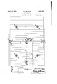
In describing the invention in detail, reference will be had to the accompanying drawings wherein like characters denote like or correspondingparts throughout the several views, and in which Figure 1 is a sectional view through one'of the platforms and showing the barrier in raised position. 7 I
Figure 2 is a section on line 22 of Figure 3. i
Figure 3 is a section on the line 33 of Figure 1.,
Figure 4 is a detailed sectional view of on of the roller supporting posts.
Figure 5 is a section on line 55 of Figure 3.
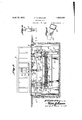
In these drawings, the a pit extending acrossthe highway at each side of the track and the numeral 2' indicates a platform covering the pit and having vertical movement so that the platform will be lowered when a vehiclepasses from the high{ way onto the same. The walls of the pit are formed with shoulders 3 to limit the down,- ward movement of the platform. I A barrier or gate 4 passes through a slot 5 extending transversely inthe platform. A pair of posts 6 is located'in the pit adjacent each side thereof, the posts of each pair being connected together by a cross piece7. The'upper ends of the posts are formed with the slots numeral 1 indicates 8 for receiving the pintl-es of the spring roll- 1 ers 9', it being understood that a roller is supported by each pair ofposts. The housing of each roller is fastened in a bracket 10 carried by the cross piece 7 and the ends of the .housing are closed 'by the rotary caps 11- which carry the pintles. A shaft 12 passes through the housing and is connectedto' the caps. The springs 13 are carried bythe shaft, the outer ends of the springs being attached to the caps and their inner ends are fastened to a stationary part so that when the springs are wound they will actto turn the caps. A pair of weightedlevers 14 islocated in the pit and each lever is formed with a yoke shaped outer end, the limbs of which I are connected to the caps by having square openings therein through which square parts are slotted, as at" 16 to' receive a bar 16 which ways' if desired.
A pair of tubular members 20 is attached 'tothe bottom of the platformat each side of Thus the levers are .l rocked by the spring rollers The weights 15 v r are carried by'the outerends of the limbs of the levers; Theinner ends of the levers the barrier and a rod21 has its upper end engaging each member, the lower end of the rod being forked and connected to; a limb of a lever. A pair of links .22 is connected to each tubular memberand: each link has "its upper end fittingin a recess in a-flange formed; on the lower end of the tubular memher. These recesses are so formed that thev I permit them to swing inwardlv to a certain extent. A second pair of links 23' is pivoted 'to the lower ends of the first pair and the in the pit, eachpair beingarranged adjacent each link assembly with the rollers 26 e at the upper ends of the posts engaging the outeredges of the pair of lower links23. 1 Thus it will be'seenthatithe'leversunder limit'the outward movement of the'links but I the action of the spring rollers will hold the platform and the gate in raised position, as shown in Figures 1 and 3, with the gate forming a barrier across the road. When a vehicle passes onto the platform the weight thereof will lower the platform and this lowering movement of the platform will cause the tubular membersx20 to force the rods 21 and the links carried thereby downwardly to lower the levers and as the lower links 23 are pressed inwardly by the rol 26, the link assemblies are lengthened and thus cause the rods 21 to move downwardly:
to a greater extent than the platform and at a greater speed so that the levers are lowered to a suificient extent to move the gate downwandly sothe vehicle can pass over it. When the vehicle passes off the platform the spring; rollers raise the gate and platform to: their. nor-mal positions.
A latch 27 is provided for locking the gate in, raised position and this latch isoperated by atrain approaching the crossingv through means of the magnet 28- the circuit 29 of which. is closed by said train. After the train. passes the crossing the circuit is broken and the latch returns to inoperative. position. Thus. the gate cannot be lowered by a vehicle running; onthe-platform when a train is: approaching the crossing.
i The gate has on its front. facethe Words Ride onthe platform? so as to inform driversof. vehicles that they must ride on .the platform in order to lower: the gate and I also provide Stop and Go signals to notify. the drivers when togo ahead and when tostopr. These words are carried by alstationary plate 30 attached tothe gateiand enclosed by a casing 31 having a window therein through which one set or the other of. the signal wordsa-re visible. This-casing is movably arranged on the gate and it is It is thought from the foregoing description that the advantages and novel features of the invention will be readily apparent.
It is to be understood that changes may be made in the construction and in the combination and arrangement of the several parts, providedzthat such changesfallwithin the scopeof the; appended claim;
What I claim is A device of the class described, comprising a centrally slotted vertically movable platform, a Vertically movable gate passing through the slot inthe platform, weighted swinging levers located under the platform andhavi'ng pin and slot connections with the gate, spring meanscoacting with the swinging, connections of the levers for normally holding the latter in a position wi-thtthe gate raised,.toggles oonnectingthe platform with the-levers, means-active onthe. toggleswhere- .by the platform; Will be normally held in raised position, said levers acting to, lower the gate when the platform is'lowered by a vehicle rldin-g upon-thesame, train operated means for locking the gate inraised position when: a train; approaches the.- platform, Stop and.Go signals on the gate and operatively associated with the gate and platform,..and, means for, exposing the Stop signal. within? the gate when. the latter is raised .andalso theGo signal when the'gate is being lowered.
In testimony whereof I affix my, signature.
' FRED H. 'SHETLER.
connected at its lower end to-a' rod 32 which has a roller 33atitslower end which istengaged by a spring actuated pivoted. member 34 at the lower face of; the platform; Ehis member normally holdslthe casing a post tion with the Stop signals. appearing throughthe window butwhen the platform islowered a projection 35 thereon will. engage a bell crank 36 pivoted to a wall. of the pit and; cause said bell crank to pull upon acable 37- andi thus move the member 34 out of engagement withthe roller 33so that the casing. will drop and display the Go signals.
The device will act to cause drivers of vehicles to check their speed asthey approach the crossing. and then by riding on the pla form thegate will be lowered if no train is coming. sothat the vehicleican proceed across the track. If a train: isv coming however; the gate will be locked in raised position and the vehicle cannot pass on the-track until the train passes-the-crossing.
Priority Applications (1)
| Application Number | Priority Date | Filing Date | Title |
|---|---|---|---|
| US498798A US1853934A (en) | 1930-11-28 | 1930-11-28 | Crossing gate |
Applications Claiming Priority (1)
| Application Number | Priority Date | Filing Date | Title |
|---|---|---|---|
| US498798A US1853934A (en) | 1930-11-28 | 1930-11-28 | Crossing gate |
Publications (1)
| Publication Number | Publication Date |
|---|---|
| US1853934A true US1853934A (en) | 1932-04-12 |
Family
ID=23982543
Family Applications (1)
| Application Number | Title | Priority Date | Filing Date |
|---|---|---|---|
| US498798A Expired - Lifetime US1853934A (en) | 1930-11-28 | 1930-11-28 | Crossing gate |
Country Status (1)
| Country | Link |
|---|---|
| US (1) | US1853934A (en) |
Cited By (3)
| Publication number | Priority date | Publication date | Assignee | Title |
|---|---|---|---|---|
| US2588502A (en) * | 1947-05-09 | 1952-03-11 | Fred P Dunn | Parking way control system |
| US3233351A (en) * | 1963-09-06 | 1966-02-08 | Herbert B Cook | Vertical vehicle operated gates |
| WO2011029737A1 (en) * | 2009-09-10 | 2011-03-17 | Georg Wirrer | Support arrangement for a lift gate that can be lowered into a subsurface shaft |
-
1930
- 1930-11-28 US US498798A patent/US1853934A/en not_active Expired - Lifetime
Cited By (3)
| Publication number | Priority date | Publication date | Assignee | Title |
|---|---|---|---|---|
| US2588502A (en) * | 1947-05-09 | 1952-03-11 | Fred P Dunn | Parking way control system |
| US3233351A (en) * | 1963-09-06 | 1966-02-08 | Herbert B Cook | Vertical vehicle operated gates |
| WO2011029737A1 (en) * | 2009-09-10 | 2011-03-17 | Georg Wirrer | Support arrangement for a lift gate that can be lowered into a subsurface shaft |
Similar Documents
| Publication | Publication Date | Title |
|---|---|---|
| US1853934A (en) | Crossing gate | |
| US1555386A (en) | Grade-crossing safety apparatus | |
| US1672723A (en) | Vehicle-actuated gate | |
| US1765906A (en) | Grade-crossing safety equipment | |
| US1136793A (en) | Railroad safety device. | |
| US1865297A (en) | Railroad crossing gate | |
| US373642A (en) | oaeey | |
| US1377901A (en) | Gate | |
| US1768587A (en) | Level gate | |
| US345412A (en) | Automatic railway-signal | |
| US1812866A (en) | Railroad gate | |
| US1343023A (en) | Automatic gate | |
| US1520392A (en) | Automatic railway-crossing gate | |
| US1563142A (en) | Railway-crossing gate | |
| US1686771A (en) | Automatic railroad-crossing gate and signal | |
| US886321A (en) | Automatic gate for railroad-crossings. | |
| US1475272A (en) | Automatic gate-operating mechanism | |
| US787895A (en) | Railway signal and gate. | |
| US1675447A (en) | Safety gate for railway crossings | |
| US375653A (en) | Railroad-gate | |
| US1527110A (en) | Railroad-crossing signal | |
| US1512580A (en) | Automatic safety gate for railroad crossings | |
| US1212106A (en) | Gate-operator. | |
| US1505449A (en) | Automatic grade-crossing signal | |
| US1518646A (en) | Railroad-crossing device |