US1853933A - Shock absorber - Google Patents
Shock absorber Download PDFInfo
- Publication number
- US1853933A US1853933A US158898A US15889827A US1853933A US 1853933 A US1853933 A US 1853933A US 158898 A US158898 A US 158898A US 15889827 A US15889827 A US 15889827A US 1853933 A US1853933 A US 1853933A
- Authority
- US
- United States
- Prior art keywords
- friction
- spring
- shoe members
- hollow
- load
- Prior art date
- Legal status (The legal status is an assumption and is not a legal conclusion. Google has not performed a legal analysis and makes no representation as to the accuracy of the status listed.)
- Expired - Lifetime
Links
- 230000035939 shock Effects 0.000 title description 21
- 239000006096 absorbing agent Substances 0.000 title description 17
- 239000003381 stabilizer Substances 0.000 description 15
- 230000000284 resting effect Effects 0.000 description 4
- 238000010276 construction Methods 0.000 description 3
- 230000014509 gene expression Effects 0.000 description 2
- 210000003141 lower extremity Anatomy 0.000 description 2
- 230000000087 stabilizing effect Effects 0.000 description 2
- 102000007469 Actins Human genes 0.000 description 1
- 108010085238 Actins Proteins 0.000 description 1
- 229910000831 Steel Inorganic materials 0.000 description 1
- 230000004323 axial length Effects 0.000 description 1
- 230000004048 modification Effects 0.000 description 1
- 238000012986 modification Methods 0.000 description 1
- 239000010959 steel Substances 0.000 description 1
- 210000001364 upper extremity Anatomy 0.000 description 1
Images
Classifications
-
- B—PERFORMING OPERATIONS; TRANSPORTING
- B61—RAILWAYS
- B61F—RAIL VEHICLE SUSPENSIONS, e.g. UNDERFRAMES, BOGIES OR ARRANGEMENTS OF WHEEL AXLES; RAIL VEHICLES FOR USE ON TRACKS OF DIFFERENT WIDTH; PREVENTING DERAILING OF RAIL VEHICLES; WHEEL GUARDS, OBSTRUCTION REMOVERS OR THE LIKE FOR RAIL VEHICLES
- B61F5/00—Constructional details of bogies; Connections between bogies and vehicle underframes; Arrangements or devices for adjusting or allowing self-adjustment of wheel axles or bogies when rounding curves
- B61F5/02—Arrangements permitting limited transverse relative movements between vehicle underframe or bolster and bogie; Connections between underframes and bogies
- B61F5/04—Bolster supports or mountings
- B61F5/12—Bolster supports or mountings incorporating dampers
Definitions
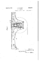
- Fig. 1 is a view in 'vertical section through' a portion of the side frame of a passenger truck showing a shock absorber mechanismv embodying the invention
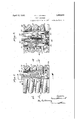
- Fig. 2 ⁇ is a view partly in side elevation and partly in vertical section of the shock absorber device shown in Fig; 1 and taken on an enlarged scale
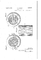
- Fig. 3 is a view in vertical section taken on the line 3 3 of Fig. 2
- Fig. 4 is a view in horizontal section taken on the lline LA of Fig. 2
- Fig. 5 is a view in horizontal section taken on the line 5 5 of Fig. 2
- Fig. 6 is a view in side elevation of a friction shoe member forming part of the device shown in Figs. 1 and 2
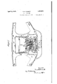
- Fig. 7 is a view in ventical section showing' a modified form of the device embodying the invention applied4 to a freight car truck construction.
- My invention relates to stabilizer or shock absorber mechanism capable of application to the trucks of railway cars, the mechanism be* ing particularly useful in preventing bouncing action in the car body such as tends to be producedV at cross-overs andl at uneven points in the track.
- the invention is 'particularly "applicable for use with passenger trucks for improving the stability and riding qualities of the cars, and with cars used in fast freight service to prevent damage to fragile goods. 1
- My invention comprises the use of a spiral friction device for use in the truck structure of railway cars, the device being shown, for convenience, inconnection with a passenger truck construction and also as applied to a freight car truck.
- the device includes a hollow friction cylinder having frictional en gagement with a plurality of friction shoe members together with wedging members a1'- ranged to bring the parts into frictional relation when a spring member surrounding the hollow friction cylinder is compressed.
- the parts, as a whole, are mounted in a compact relation one within another. All the operative part-s of the structure are con- 'tained within the axial length of the enclosing weight receiving spring.
- Fig. 1 there is shown in section a portion of the side frame member 10 of passenger truck.
- the center axle 11 of the six-wheel truck structure a part of which is shown, is provided with the usual journal box 12, on top of which rests a stabilizer or shock absorber structure 13 which forms the subject matter 0f the invention set forth herein.
- the journal box structure 12- is provided Withup- Wardly extending flangeslll at its lateral edges which provide a seat in which the stabilizer structure is received and centered in ⁇ a proper working position.
- equalizer arm 15 In this type of l truck, that portion of the car load, which is designed to be carried by the center pairof wheels on the axle 11, is transmitted thereto from the side frame member 10 by means of equalizer arms 15 and 16.
- the ends of the 'equalizer arms bear against'the upper side of a cap member 17 which rests onthe stabilizer structure 13, the cap member 17 being provided with4 downwardly projecting anges 18 which enclose the upper extremity of the stabilizer device.
- the equalizer arm 15 is shown as pivoted to the side frame structure at 19, the pivotal point of the equalizer arm 16 not being shown.
- the stabilizer or shock absorber structure includes a hollow friction cylinder member 20 which is provided with downwardly extending supporting members 21 having a diametrically opposed relation to each other and attached by means of the screws 22 to a base plate 23 forming part of the structural assembly; Within the hollow cylindrical member 20 is mounted a pair of friction shoe members 2-1, each of which is provided 'with a helical 0r angular groove 25 in which is received a radial inwardly extending spiral lug 26 formed integrally with the inner surface of the hollow cylindrical member 20.
- a tubular wedging member 27 having a wedging surface 28 formed at its lower extremity and an annular friction wedging surface 29 formed von the lower face of an annular flange member 30 formed on the upper end of the wedging member 27.
- the inclined face 28 formed lat the lower end of the wedging member 27 is arranged to engage correspondingly inclined faces 31 forming the upper faces of radial inwardly extending lug members 32 formed on the lower ends of the friction shoe members 2'4.
- the upper annular inclined surface 29 of the wedging member 27 engages correspondingly inclined faces 33 forming the upper terminal edges of the friction shoe members 24.
- a weight-resistingcoil spring member 34 is mounted in enclosing relation to the parts described and bears atits lower end against the base plate 23 previously referred to.
- the member 36 forms by this arrangement a connecting structure between the weight-resisting spring Y 34 and the working parts of the stabilizer device.
- a bolt 39 engages with a restricted portion 40 of the tubular wedging member 27 and withy the base plate 23, passing through an opening 41, provided for-.the purpose in the bridging member 37, and
- a washer 38 is interposed betweenV the bridging member 37 of the member 36V 'ber 27 produced by the load which rests thereon.
- a feature of the invention resides in the arrangement of the parts to provide clearances or gaps 42 and 43 between the friction friction shoe members 24. This clearance,
- the clearance space 42 is smaller than the clearance space 43, as will mounting includes a base member 48 having Y
- a base member 48 having Y
- Fig. 7 of thel drawings there is shownan application of the inventlon to a freight car truck structure.
- a portion of a side frame member of the truck is shown at 45 with the bolster being shown in section at 46 and with the stabilizer structure being shown generally' at 47.
- the stabilizer structure is so mounted as to have a universal or'ball and socket support to provide for both longitudinal and lateral movement of the supported bolster member.
- This universal a convex seat 49 in which lrests a spring seat member 50 having a concavesurface 51 which engages the convex surface 49 'of the base member 48.
- the stabilizer structure follows that alreadydescribed inconnection with the passenger truck mounting.
- the spring action .of the stabilizer is supplemented by the action of a coil spring 52 mounted in enclosing relation to the stabilizer structure and arranged to i top of the stabilizer wedge member 27 and the lower surface of the bolster 46, the stabilizer structure does not come into action until the spring 52 -hasbeen compressed to a certain extent.
- the large spring 52 takes up all ordinary or relatively minor vibrations while vibrations of greater intensity or magnitude are damped bythe friction action of the stabilizer structure.
- This compactness is achieved by the mounting of the structure parts in a telescopic or co-extensive arrangement whereby all the parts are located within the longitudinally separated limits of the en ⁇ closing springstructure.
- This compactness of arrangement is an important feature of the invention in that it provides for the location of structure effective for the purpose in a relatively restricted space.
- a shock absorber structure a hollow friction member, friction shoe members having frictional engagement with the inner surjface of the hollow friction member and movable. axially thereof, a load resisting spring member mounted in enclosing relation to said hollow friction member, a connecting member seated on the uppei ⁇ end of the spring and supporting said friction shoe members at their lower ends, and a load receiving member arranged to engage said friction shoe members and to move them axially of the hollow friction member against the pressure of the spring under the pressure of the load.
- a shock absorber structure a hollow friction member, friction shoe members havin;r frictional engagement with the inner surface of the hollow friction member and movable helically thereof, a load resisting spring member mounted in enclosing relation to said hollow friction member, connecting means resting onthe upper end of the spring member and supporting said friction shoe members at their lower ends, and a load receiving member arranged to engage said friction shoe members and to move them against vthe resistance -of the spring under the .pressure of a load.
- a shock absorber structure a hollow friction member, friction shoe members having frictional engagement with the in ner surface of the hollow friction member, interen- ⁇ gaging spirally arranged luzgr and groove members on the linterengaging surfaces of the friction shoe members and saidghollow friction member, a load resisting spring mounted in enclosing relation to said hollow friction member, aconnecting member resting'on the l 4.
- a shock absorber structure In a shock absorber structure, a hollow friction member, friction shoe members hav ⁇ ing frictional engagement with the inner surface of the hollow friction member, interengaging spirally arranged lugs and groovesl formed on the interengaging surfaces of the friction shoe members and the'hollow friction member, a load resisting spring mounted in enclosing relation to said hollow friction member, a connecting member resting on the upper end of the spring and supporting said friction shoe members at their lower ends, and a load receiving wedging member having telescopic relation to ⁇ said friction shoe members and arranged to force said friction shoe members outwardly to create pressure against the interengaging frictional surfaces when the wedging member is forced downwardly agailnst the resistance of the spring under the pressure of the load.
- a shock-absorber structure a hollow friction member supported in a recess in a truck side frame member, Afriction shoe members having frictional engagement with the inner surface of the hollowfriction member and movable axially thereof, a load resisting spring member mounted in enclosing v tionalengagement therewith, a load receivrelation to said hollow friction member, a connecting member resting on the upper end of said load resisting spring and supporting said friction shoe members lat their.
- a load receiving member arranged to move said friction shoe members axially of said hollow fr iction member against the resist-ance of said spring, a load receiving spring member mounted in enclosingrelation to said first named spring member and bearing at its upper end against the lower surface of a truck bolster, said last named spring being adapted to hold the rbolsternormally in a position above and out'of contact with said load receiving member whereby minor vibrations are absorbed by the outer spring member and, vibrations of greater magnitude are damped by the action of the frictional engagement-of theshock absorber parts.
- a shock absorber comprising a friction column and friction shoes arranged for fricing member arranged to engage said friction lshoes and to move them axially of the friction column, a load resisting spring member mounted in enclosing relation to saidv friction column 'and load receiving member, and a connecting member seated on the upper end of the spring and supporting said friction shoes at their-lower ends.
- abase member a hollow friction member enga -ng said base member, friction shoe mem ers having frictional engagement with the inner surface of the hollow friction member and movable axially thereof, a member for supporting .said shoes and having openings therein for receiving portions of said friction member, and a load receiving member co-extensive with the friction shoe members and having wedging engagement at both ends of said friction shoe members, said load receiving member actin under the pressure of the load to force they riction shoe members radially outward to exert pressure against the surface of the hollow friction member with which they are in Contact.
Landscapes
- Engineering & Computer Science (AREA)
- Mechanical Engineering (AREA)
- Vehicle Body Suspensions (AREA)
Description
April 12, 1932 E. H. SCHMIDT i 1,853,933
SHOCK ABSORBER Orginl Filed Jan. 4, 1927 4 Sheets-Sheet l www@ qfm',
April 12,` 1932. E. H. SCHMIDT 1,853,933
\ SHOCK ABSORBER original Filed Jan. 4, 1927 4 sheets-sheetv 2 www im ylllllllllllllllllllllllll April 12, 1932. E. H. SCHMIDT 4Sheets-Sheet 3 Original Filed Jan. 4. 1927 vwamtoz N 6W@ H. 5 JMA* mi, 1L; am a April l2, 1.932. l E. H. SCHMIDT 1,853,933
' SHOCK ABSORBER Original Filed Jan'. 4, 192'? 4 Sheet's-Sheet v4 K i S14/vento@ 35/ umm/Mm Patented Apr. 12, 1932v UNITED STATES PATENT OFFICE ERNEST H. SCHMIDT, OF CLEVELAND HEIGHTS, OHIO, ASSIGNOR T NATIONAL MAL- LEABLE AND STEEL CASTINGS COMPANY, OF CLEVELAND, OHIO, A'CORPORATION OF OHIO snoei: ABSORBEB.
' Application led January 4, 1927, Serial No. 158,898. Renewed December 4, 1931.
Fig. 1 is a view in 'vertical section through' a portion of the side frame of a passenger truck showing a shock absorber mechanismv embodying the invention; Fig. 2 `is a view partly in side elevation and partly in vertical section of the shock absorber device shown in Fig; 1 and taken on an enlarged scale; Fig. 3 is a view in vertical section taken on the line 3 3 of Fig. 2; Fig. 4 is a view in horizontal section taken on the lline LA of Fig. 2; Fig. 5 is a view in horizontal section taken on the line 5 5 of Fig. 2; Fig. 6 is a view in side elevation of a friction shoe member forming part of the device shown in Figs. 1 and 2; and Fig. 7 is a view in ventical section showing' a modified form of the device embodying the invention applied4 to a freight car truck construction.
My invention relates to stabilizer or shock absorber mechanism capable of application to the trucks of railway cars, the mechanism be* ing particularly useful in preventing bouncing action in the car body such as tends to be producedV at cross-overs andl at uneven points in the track. The invention is 'particularly "applicable for use with passenger trucks for improving the stability and riding qualities of the cars, and with cars used in fast freight service to prevent damage to fragile goods. 1
My invention comprises the use of a spiral friction device for use in the truck structure of railway cars, the device being shown, for convenience, inconnection with a passenger truck construction and also as applied to a freight car truck. The device includes a hollow friction cylinder having frictional en gagement with a plurality of friction shoe members together with wedging members a1'- ranged to bring the parts into frictional relation when a spring member surrounding the hollow friction cylinder is compressed. The parts, as a whole, are mounted in a compact relation one within another. All the operative part-s of the structure are con- 'tained within the axial length of the enclosing weight receiving spring. An angular or helical movement is alsof provided between the friction cylinder and the 4friction shoe members to add to the frictionalresistance provided by the engagement of parts and also to distribute wear more uniformly and over a greater area .of the interengaging parts. My invention also comprises various other features which I shall hereinafter describe and claim. While the invention has been described and illustrated in connection with railway car trucks, it will be apparent that its utility is not conned thereto.
Referring to the drawings for a more detailed description of the invention, in Fig. 1 there is shown in section a portion of the side frame member 10 of passenger truck. The center axle 11 of the six-wheel truck structure, a part of which is shown, is provided with the usual journal box 12, on top of which rests a stabilizer or shock absorber structure 13 which forms the subject matter 0f the invention set forth herein. The journal box structure 12-is provided Withup- Wardly extending flangeslll at its lateral edges which provide a seat in which the stabilizer structure is received and centered in `a proper working position. In this type of l truck, that portion of the car load, which is designed to be carried by the center pairof wheels on the axle 11, is transmitted thereto from the side frame member 10 by means of equalizer arms 15 and 16. The ends of the 'equalizer arms bear against'the upper side of a cap member 17 which rests onthe stabilizer structure 13, the cap member 17 being provided with4 downwardly projecting anges 18 which enclose the upper extremity of the stabilizer device. The equalizer arm 15 is shown as pivoted to the side frame structure at 19, the pivotal point of the equalizer arm 16 not being shown.
The stabilizer or shock absorber structure includes a hollow friction cylinder member 20 which is provided with downwardly extending supporting members 21 having a diametrically opposed relation to each other and attached by means of the screws 22 to a base plate 23 forming part of the structural assembly; Within the hollow cylindrical member 20 is mounted a pair of friction shoe members 2-1, each of which is provided 'with a helical 0r angular groove 25 in which is received a radial inwardly extending spiral lug 26 formed integrally with the inner surface of the hollow cylindrical member 20. It will be seen that the' relation of the cylindrical friction member 20 and the friction shoe members 24 -is such that frictional engagement is effected between the adjacent surfaces of lthe members and between the spiral lugs of the member 2O and the surfaces of the grooves 25 formed in the friction shoe members 24.
Mounted between the friction shoe members 24 is a tubular wedging member 27 having a wedging surface 28 formed at its lower extremity and an annular friction wedging surface 29 formed von the lower face of an annular flange member 30 formed on the upper end of the wedging member 27. The inclined face 28 formed lat the lower end of the wedging member 27 is arranged to engage correspondingly inclined faces 31 forming the upper faces of radial inwardly extending lug members 32 formed on the lower ends of the friction shoe members 2'4. The upper annular inclined surface 29 of the wedging member 27 engages correspondingly inclined faces 33 forming the upper terminal edges of the friction shoe members 24.
A weight-resistingcoil spring member 34 is mounted in enclosing relation to the parts described and bears atits lower end against the base plate 23 previously referred to. On the upper end of the spring 34 an outwardly extending .annular flange member 35, which is formed integrally with the upper end 0f an annular member 36 across the lower end of which a bridging member 37 extends between the downwardly extending supporting members 21 of the hollow friction cylinder 20, is provided. The member 36 forms by this arrangement a connecting structure between the weight-resisting spring Y 34 and the working parts of the stabilizer device.
andthe lower extremities'of the friction shoe members 24. A bolt 39 engages with a restricted portion 40 of the tubular wedging member 27 and withy the base plate 23, passing through an opening 41, provided for-.the purpose in the bridging member 37, and
functions to4 hold the parts in assembled re-` A washer 38 is interposed betweenV the bridging member 37 of the member 36V 'ber 27 produced by the load which rests thereon.
It will be clear that downward movement of the friction shoes 24 is resisted by the interengagement between the friction shoes and the connecting member 36 which engages the upper end of the load resisting spring 34 and it will be .seen that the frictional resistance which is developed between the mutually contacting parts described is added to the resistance of the spring to eectively cushion the downward thrust of the adjacent ends of the equalizer arms 15 and 16 of the truck structure. Under reverse conditions of operation, that is, when the spring 34 acts to restore the parts to a non-compressed condition, the bridge member 37 of the connecting member 36 is raised, bringing about a correspondinglift of the friction shoe members 24 with a reverse angular movement of the shoe members with-relation to the hollow friction cylinder 20 and thereby effecting the'restoration of the parts to normal position.
A feature of the invention resides in the arrangement of the parts to provide clearances or gaps 42 and 43 between the friction friction shoe members 24. This clearance,
which occurs only inthe normal and nonr compressed condition. of the parts, provides for a slight direct downward movement of the shoe members 24 before the angular or y helical movement of the shoe begins in a compressing movement of the parts. By thus arranging for the spiral or helical movement to begin only after the clearance has been fully taken up by the straight-line downward movement I provide a relatively soft action during the straight-line travel of the parts for taking up ordinary minor vibrations. When the spiral action comes into play, the friction between the parts builds up' rapidly because of the angular twist in the relative movement of the arts, thereby making adequate provision or taking up more substantial shocks, such as are encoun- `tered when the truck is passing over a low spot in the track. A'
It will be seen that the clearance space 42 is smaller than the clearance space 43, as will mounting includes a base member 48 having Y Referring to Fig. 7 of thel drawings there is shownan application of the inventlon to a freight car truck structure. In this figure a portion of a side frame member of the truck is shown at 45 with the bolster being shown in section at 46 and with the stabilizer structure being shown generally' at 47. In this form'of the invention, the stabilizer structure is so mounted as to have a universal or'ball and socket support to provide for both longitudinal and lateral movement of the supported bolster member. This universal a convex seat 49 in which lrests a spring seat member 50 having a concavesurface 51 which engages the convex surface 49 'of the base member 48. In this construction, the stabilizer structure follows that alreadydescribed inconnection with the passenger truck mounting. However, the spring action .of the stabilizer is supplemented by the action of a coil spring 52 mounted in enclosing relation to the stabilizer structure and arranged to i top of the stabilizer wedge member 27 and the lower surface of the bolster 46, the stabilizer structure does not come into action until the spring 52 -hasbeen compressed to a certain extent. By this arrangement of structure, the large spring 52 takes up all ordinary or relatively minor vibrations while vibrations of greater intensity or magnitude are damped bythe friction action of the stabilizer structure.
It will be seen that I have thus provided a stabilizing or shock absorbing structure adapted for use in the truck lconstruction either of passenger cars or of freight cars and characterizedby its compactness and general adaptability for use in the restricted space available for the purpose. This compactness is achieved by the mounting of the structure parts in a telescopic or co-extensive arrangement whereby all the parts are located within the longitudinally separated limits of the en` closing springstructure. This compactness of arrangement is an important feature of the invention in that it provides for the location of structure effective for the purpose in a relatively restricted space. By reason ofthis, I aml enabled -`to replace 'the ordinary coil spring members heretofore usedgin this situation by the spring friction shock absorbing devices described herein, vthereby adding in a substantial degree to the eectiveness of the stabilizing or shock absorbing function.
Matter disclosed but not claimed herein is claimed in my' copending applications Serial Numbers 124.560, tiled July 24,l 1926,Y and 249,521, filed January 26, 1928.
The terms and expressions whichI have employed are used as terms of description and not of limitation, and I have no intention, in
the use of such terms and expressions, of
fexcluding any mechanical equivalents of the features shown and described, or portions thereof, but recognize that various structural modifications are possible Within the scope of the invention claimed.
lVhat I claim is:
1. In a shock absorber structure, a hollow friction member, friction shoe members having frictional engagement with the inner surjface of the hollow friction member and movable. axially thereof, a load resisting spring member mounted in enclosing relation to said hollow friction member, a connecting member seated on the uppei` end of the spring and supporting said friction shoe members at their lower ends, anda load receiving member arranged to engage said friction shoe members and to move them axially of the hollow friction member against the pressure of the spring under the pressure of the load.
2. In a shock absorber structure, a hollow friction member, friction shoe members havin;r frictional engagement with the inner surface of the hollow friction member and movable helically thereof, a load resisting spring member mounted in enclosing relation to said hollow friction member, connecting means resting onthe upper end of the spring member and supporting said friction shoe members at their lower ends, and a load receiving member arranged to engage said friction shoe members and to move them against vthe resistance -of the spring under the .pressure of a load.
3. In a shock absorber structure, a hollow friction member, friction shoe members having frictional engagement with the in ner surface of the hollow friction member, interen- `gaging spirally arranged luzgr and groove members on the linterengaging surfaces of the friction shoe members and saidghollow friction member, a load resisting spring mounted in enclosing relation to said hollow friction member, aconnecting member resting'on the l 4. In a shock absorber structure, a hollow friction member, friction shoe members hav` ing frictional engagement with the inner surface of the hollow friction member, interengaging spirally arranged lugs and groovesl formed on the interengaging surfaces of the friction shoe members and the'hollow friction member, a load resisting spring mounted in enclosing relation to said hollow friction member, a connecting member resting on the upper end of the spring and supporting said friction shoe members at their lower ends, and a load receiving wedging member having telescopic relation to `said friction shoe members and arranged to force said friction shoe members outwardly to create pressure against the interengaging frictional surfaces when the wedging member is forced downwardly agailnst the resistance of the spring under the pressure of the load.
l 5. In a shock-absorber structure, a hollow friction member supported in a recess in a truck side frame member, Afriction shoe members having frictional engagement with the inner surface of the hollowfriction member and movable axially thereof, a load resisting spring member mounted in enclosing v tionalengagement therewith, a load receivrelation to said hollow friction member, a connecting member resting on the upper end of said load resisting spring and supporting said friction shoe members lat their. lower ends, a load receiving member arranged to move said friction shoe members axially of said hollow fr iction member against the resist-ance of said spring, a load receiving spring member mounted in enclosingrelation to said first named spring member and bearing at its upper end against the lower surface of a truck bolster, said last named spring being adapted to hold the rbolsternormally in a position above and out'of contact with said load receiving member whereby minor vibrations are absorbed by the outer spring member and, vibrations of greater magnitude are damped by the action of the frictional engagement-of theshock absorber parts.
6. In a railway car truck having a load transmitting member and ak load receiving member, friction shock absorbing means interposed `therebetween and radial equalizing means disposed between said shock absorbing meansand ones-.of the aforesaid members to provide for relative lateral movement between the load-"transmitting and load receiv-l ing members;
7. A shock absorber comprising a friction column and friction shoes arranged for fricing member arranged to engage said friction lshoes and to move them axially of the friction column, a load resisting spring member mounted in enclosing relation to saidv friction column 'and load receiving member, and a connecting member seated on the upper end of the spring and supporting said friction shoes at their-lower ends.
' 8. In a shock-absorber structure, abase member, a hollow friction member enga -ng said base member, friction shoe mem ers having frictional engagement with the inner surface of the hollow friction member and movable axially thereof, a member for supporting .said shoes and having openings therein for receiving portions of said friction member, and a load receiving member co-extensive with the friction shoe members and having wedging engagement at both ends of said friction shoe members, said load receiving member actin under the pressure of the load to force they riction shoe members radially outward to exert pressure against the surface of the hollow friction member with which they are in Contact.
9. In a railway car truck having a load-4 transmitting member and a load receiving member, friction shock absorbing means interposed therebetween, and radial equalizing ERNEST SCHMIDT.
Priority Applications (1)
| Application Number | Priority Date | Filing Date | Title |
|---|---|---|---|
| US158898A US1853933A (en) | 1927-01-04 | 1927-01-04 | Shock absorber |
Applications Claiming Priority (1)
| Application Number | Priority Date | Filing Date | Title |
|---|---|---|---|
| US158898A US1853933A (en) | 1927-01-04 | 1927-01-04 | Shock absorber |
Publications (1)
| Publication Number | Publication Date |
|---|---|
| US1853933A true US1853933A (en) | 1932-04-12 |
Family
ID=22570195
Family Applications (1)
| Application Number | Title | Priority Date | Filing Date |
|---|---|---|---|
| US158898A Expired - Lifetime US1853933A (en) | 1927-01-04 | 1927-01-04 | Shock absorber |
Country Status (1)
| Country | Link |
|---|---|
| US (1) | US1853933A (en) |
Cited By (5)
| Publication number | Priority date | Publication date | Assignee | Title |
|---|---|---|---|---|
| US2431375A (en) * | 1943-11-29 | 1947-11-25 | Miner Inc W H | Friction shock absorbing mechanism |
| US3400668A (en) * | 1966-02-09 | 1968-09-10 | Gen Steel Ind Inc | Pneumatic railway vehicle suspension |
| US4428302A (en) | 1982-02-10 | 1984-01-31 | The Budd Company | Emergency spring system for a railway car |
| US11111978B2 (en) | 2017-12-14 | 2021-09-07 | Xr Reserve, Llc | Mechanical force breaker |
| US11613929B2 (en) | 2019-11-08 | 2023-03-28 | Xr Dynamics Llc | Dynamic drilling systems and methods |
-
1927
- 1927-01-04 US US158898A patent/US1853933A/en not_active Expired - Lifetime
Cited By (5)
| Publication number | Priority date | Publication date | Assignee | Title |
|---|---|---|---|---|
| US2431375A (en) * | 1943-11-29 | 1947-11-25 | Miner Inc W H | Friction shock absorbing mechanism |
| US3400668A (en) * | 1966-02-09 | 1968-09-10 | Gen Steel Ind Inc | Pneumatic railway vehicle suspension |
| US4428302A (en) | 1982-02-10 | 1984-01-31 | The Budd Company | Emergency spring system for a railway car |
| US11111978B2 (en) | 2017-12-14 | 2021-09-07 | Xr Reserve, Llc | Mechanical force breaker |
| US11613929B2 (en) | 2019-11-08 | 2023-03-28 | Xr Dynamics Llc | Dynamic drilling systems and methods |
Similar Documents
| Publication | Publication Date | Title |
|---|---|---|
| US2129408A (en) | Truck stabilizer | |
| US7174837B2 (en) | Three-piece motion control truck system | |
| EP2123534A2 (en) | Railroad freight car sidebearing | |
| US2053990A (en) | Anti-oscillating device | |
| US3748001A (en) | Resiliently biased constant contact side bearing | |
| US1810718A (en) | Car | |
| US2053989A (en) | Bolster damper | |
| US3762339A (en) | Railway truck anti-rock side bearing device | |
| US2705633A (en) | Shock absorbing means for railroad car trucks | |
| US1853933A (en) | Shock absorber | |
| US3359923A (en) | Railway bogie | |
| US2356962A (en) | Spring unit | |
| US2145891A (en) | Antishock spring | |
| US4004525A (en) | Fluid truck snubber | |
| US1956108A (en) | Combined spring and absorption means | |
| US2216473A (en) | Cushioning mechanism | |
| US3762338A (en) | Railway truck anti-rock side bearing device | |
| US2116189A (en) | Cushioning mechanism | |
| US2316592A (en) | Railway car truck | |
| US2272426A (en) | Railway truck structure | |
| US2756691A (en) | Railway vehicle truck | |
| US2797650A (en) | Railway vehicle | |
| US1712908A (en) | Shock-absorbing bolster | |
| US2151603A (en) | Center plate cushioning device | |
| US2717559A (en) | Railway truck spring suspension |