US1853932A - Friction draft gear - Google Patents
Friction draft gear Download PDFInfo
- Publication number
- US1853932A US1853932A US124560A US12456026A US1853932A US 1853932 A US1853932 A US 1853932A US 124560 A US124560 A US 124560A US 12456026 A US12456026 A US 12456026A US 1853932 A US1853932 A US 1853932A
- Authority
- US
- United States
- Prior art keywords
- friction
- shoes
- shell
- wedge
- spring
- Prior art date
- Legal status (The legal status is an assumption and is not a legal conclusion. Google has not performed a legal analysis and makes no representation as to the accuracy of the status listed.)
- Expired - Lifetime
Links
- 230000006835 compression Effects 0.000 description 7
- 238000007906 compression Methods 0.000 description 7
- 230000035939 shock Effects 0.000 description 7
- 230000003578 releasing effect Effects 0.000 description 3
- 229910000831 Steel Inorganic materials 0.000 description 2
- 239000010959 steel Substances 0.000 description 2
- CWYNVVGOOAEACU-UHFFFAOYSA-N Fe2+ Chemical compound [Fe+2] CWYNVVGOOAEACU-UHFFFAOYSA-N 0.000 description 1
- 229910001296 Malleable iron Inorganic materials 0.000 description 1
- 239000006096 absorbing agent Substances 0.000 description 1
- 238000005266 casting Methods 0.000 description 1
- 238000010276 construction Methods 0.000 description 1
- 230000014509 gene expression Effects 0.000 description 1
- 150000002500 ions Chemical class 0.000 description 1
- 239000000463 material Substances 0.000 description 1
Images


Classifications
-
- B—PERFORMING OPERATIONS; TRANSPORTING
- B61—RAILWAYS
- B61G—COUPLINGS; DRAUGHT AND BUFFING APPLIANCES
- B61G9/00—Draw-gear
- B61G9/04—Draw-gear combined with buffing appliances
- B61G9/10—Draw-gear combined with buffing appliances with separate mechanical friction shock-absorbers
Definitions
- FIG. 6 is av perspective of the frlction shellpartly broken away
- Fig.' 7 is a perspective of one of the friction shoes
- Fig. i 8 is a front elevation .of the frictionrshell
- Fig. 9 is a ly in section.
- My invention relates to friction draft gear and comprises afriction barrel or shell engaged by a pluralityof friction shoes and containing means for-causing the shoes dur-v ing compression or release to ⁇ rotate or'have an angular movementrelative to the longitudinal axis of the shell andthereby increase vthe frictional resistance, and distribute" the wear more uniformly withinthe friction casing.
- My invention also comprises various scribe rand claim. f
- A indicates a spring caseor shell having'at its forward end outwardly extending flanges 2, which are engaged by corresponding flanges 3 on the friction case or shell B.
- the flanges 2 fand 3 are held together ⁇ by rivets 4,-the ⁇ headsl of which are made flush with the flange 2',f asis' indicated at 5 in Fig. 1.
- the spring case A is provided with wings 6 suitably reinforced with ribs 7 merging intothe sides of the case A.
- the spring case A carries one or more draft springs. 11 which Y bear at one end against the spring seat 9 and at the other end against the base 12 of the spring case A.
- a small release spring 13 is also interposed between the spring seat 9 and the/frictionV wedge 10. The parts are held in assembled relation by the retaining rod 14, which has a bearing on Vthe wedgerl() andbase 12.
- the inside face lrvofthefriction case ⁇ or shell B may, if desired,.bey tapered inwardly toward its rear end, and is preferably pro ⁇ EEICT'ION DEAET f GEA'E Y192e. ⁇ serial No. v124,560.-
- theV friction shoes 8 Cooperating with such inside face 15 and the lugs 16 -and 17 are theV friction shoes 8. These shoes 8are 'formed v with spirally shaped faces 18 which cooperate with the spiral faces 19 on the lug 16, and' witha groove 20 cooperating with the spiral faces 21A-Ona release lug 17. While in the construction shown, vthe groove is shown in the lfriction shoe cooperable with lugs on the, friction shell, itis to be understood that the' grooves may, if desired, be located n the shell v forward face'24 'of the spring'seat9, as is shown in Fig, 3. The face 24'maybe of conicalor any desired shape.
- the shoes 8 arel /7' further provided with wedging surfaces 25"; and 26, which engage the correspondingly inclined wedging surfaces 27 and 28 of the fric-Av tion wedge 10.
- a further result of the clearance between the groove y20 in the shoes and the lug 17 is to allow the shoes when the gear is again compressed to move inwardly in a straight line, until the shoes contact the spiralsurfaces 19.
- the clearance between one of the shoes and its guiding spiral may be made .greater than that between the other shoe and ⁇ its guiding spiral, thus causing one shoe to start rotation aheadof the other both during compression and release, and while the other is still moving in a straight line.
- the result of this is a graduated resistance during compression land a serial release.
- the additional clearance also is of a further advantage in distributing the lines of wear
- the friction barrel separate from the spring case is that they may be made of different materials.
- the friction chamber may be made of wear resista-nt steel, and the spring case of malleable iron.
- a friction shock absorbing mechanism a friction shell; friction shoes disposed in said shell in frictional engagement therewith; wedge for moving said shoes longitudinally of said shell; and means arranged about the circumference of said shell for rotating the shoes in opposite directions about the longitudinal axis of said shell, said ro-V tativemeans being effective during only a poi-tion of the compression and release movements of the gear.
- a friction shock absorbing mechanism comprising a friction shell having longitudition shoes; a wedge having a conicalwedging surface for engagement with said friction shoes to maintain them in frictional engagement with said shell; yieldable means for resisting movement of the shoes longitudinally of' the-shell; and means arranged ⁇ about the circumference of said shell for rotating the shoes with respectto the wedge. 4:.
- a friction shock absorbing mechanism comprising a friction shell; friction shoes;
- a central wedge member arranged to mainf ⁇ tain the friction shoes in frictional engagenient with said shell and to move them longitudinally with ⁇ respect thereto upon conipression of the mechanism; yieldable means for resisting said movement of the shoes and guiding means on the shell for causing rotative movement of the shoes, the longitudinal movement of each shoe being in the same direction and the rotative movement of therr shoes being in opposite dircetions.
- a friction shock absorbing mechanism a friction shell, friction shoes disposed in said shell in frictional engagement therewith, a wedge arranged to move the shoes iii the same longitudinal direction relative to the shell, yieldable means for resisting said movement of the shoes, and means arranged about the circumference of the shell and in fixed relation thereto for rotating the shoes in opposite directions about the longitudinal axis of said shell.
- a shock absorbing mechanism comprising a friction casing, friction shoes therein, a' wedge maintaining said friction shoes in frictional engagement with the casing, the contiguous surfaces of said casing and shoes having cooperating spiral ribs and grooves for causing the shoes to rotate with respect to the wedge as they move longitudinally with it, and a compression spring arranged to oppose the longitudinal movement of the shoes.
- a friction shock absorbing mechanism comprising a friction casing, friction shoes the casing having circumferential friction faces engaged by corresponding arc-shaped faces on the shoes, each shoe having adjacent its arc-shaped face at a distance from the edges thereof a spiral friction surface cooperating with a. corresponding spiral friction surface on the casing for rotating said shoe, a wedge for maintaining the friction shoes in frictional engagement with the casing, and for moving them longitudinally relative to it, and a compression spring arranged to oppose the longitudinal movement Y of the shoes.
- a shock absorber structure a hollow friction member, friction shoe members having frictional engagement with the inner surface of the hollovv friction member, interengaging spiral lugs and grooves on the contiguous surfaces of said hollow friction member and said friction shoe members, and a Wedging ,member having telescopic relation to said friction shoe members and arranged under pressure of the load to force said friction shoe members radially outward to exert pressure against the surfaces of the hollow friction member with Which'they are in Contact. 4 Y
Landscapes
- Engineering & Computer Science (AREA)
- Mechanical Engineering (AREA)
- Braking Arrangements (AREA)
Description
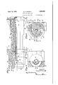
'April- 12,1932. E. H. SCHMIDT FRICTION DRAFT GEAR Filed July 24, 192e 3 sheets-sheet 1 April 12, l1932. E, H. SCHMIDT FRICTION DRAFT GEAR Filed July 24. 1926 5 Sheets-Sheet 2 April 12, 1932. E. H. SCHMIDT FRICTION DRAFT GEAR Filed July 24, 192e Svsheets-sheet 5 other features which I shall hereinafter de'-A Patented Apr. 12, 1932 UNITED STATES PATENT 1 EENEsT H. SCHMIDT, OECIQEVELANDEEIGHTS, oHIo, AssIGNoE To vNATIONAL MAE-t LEAELE AND STEEL CAsTINGs COMPANY, 0E CLEVELAND, oHIo, A CoEPoEATIoN 0E oHIo Y Application meay July 24,
with the friction wedge and one of the shoes r removed; Fig. 6 is av perspective of the frlction shellpartly broken away Fig.' 7 is a perspective of one of the friction shoes; Fig. i 8 is a front elevation .of the frictionrshell,
plan of the friction shell,part 4 f and the lugsformed on'theV friction shoe.
and Fig. 9 is a ly in section.
My inventionrelates to friction draft gear and comprises afriction barrel or shell engaged bya pluralityof friction shoes and containing means for-causing the shoes dur-v ing compression or release to `rotate or'have an angular movementrelative to the longitudinal axis of the shell andthereby increase vthe frictional resistance, and distribute" the wear more uniformly withinthe friction casing. My invention also comprises various scribe rand claim. f
Referring tothe drawings, A indicates a spring caseor shell having'at its forward end outwardly extending flanges 2, which are engaged by corresponding flanges 3 on the friction case or shell B. The flanges 2 fand 3 are held together` by rivets 4,-the` headsl of which are made flush with the flange 2',f asis' indicated at 5 in Fig. 1. At itsrear end the spring case A is provided with wings 6 suitably reinforced with ribs 7 merging intothe sides of the case A. Y Y
Within the friction chamber B are friction shoesS interposed between the springV seat 9 and thefriction wedge 1 0. ,The spring case A carries one or more draft springs. 11 which Y bear at one end against the spring seat 9 and at the other end against the base 12 of the spring case A.` A small release spring 13 is also interposed between the spring seat 9 and the/frictionV wedge 10. The parts are held in assembled relation by the retaining rod 14, which has a bearing on Vthe wedgerl() andbase 12. l
The inside face lrvofthefriction case` or shell B may, if desired,.bey tapered inwardly toward its rear end, and is preferably pro` EEICT'ION DEAET f GEA'E Y192e. `serial No. v124,560.-
vided with a'compression lug 16 and a pair. i
ofrelease lugs 17.` Cooperating with such inside face 15 and the lugs 16 -and 17 are theV friction shoes 8. These shoes 8are 'formed v with spirally shaped faces 18 which cooperate with the spiral faces 19 on the lug 16, and' witha groove 20 cooperating with the spiral faces 21A-Ona release lug 17. While in the construction shown, vthe groove is shown in the lfriction shoe cooperable with lugs on the, friction shell, itis to be understood that the' grooves may, if desired, be located n the shell v forward face'24 'of the spring'seat9, as is shown in Fig, 3. The face 24'maybe of conicalor any desired shape. The shoes 8 arel /7' further provided with wedging surfaces 25"; and 26, which engage the correspondingly inclined wedging surfaces 27 and 28 of the fric-Av tion wedge 10.
The operation of'my improved gear is as, follows: A When the gearis being compressed thefriction wedge 10 is forced rearwardly with respect to the friction shell B,`and` this in turn moves the shoes rearwardly against the ac- 86 tion of the springs 11and against thefric tion between the surfaces 22 of the shoes and the inner face 15 of. the shell B. As the shoes [8 move rearwardly, the spiral surfaces 19-on the lug 16cause theshoes 8 to rotate in opposite directions, dueto the guiding contact with the faces 18 of the shoes 8,. This causes an additional frictionalengagement between the lug 16 of theshell and the face 18 on the shoes. Further frictional resistance is also-v caused between the rear surfaces 23'of the 'shoes andthe forward face 24 of the spring seat 9 by the rotation of the shoes. The shoes thus have five friction surfaces, 18, y 22, 23, 25
and 26, which engage corresponding surfaces yon the'friction shell, wedge andspring seat. It will be seen that theprotation of the shoes in opposite directions serves to equalize the torsional forces and eliminates any tendency ofthe gear to rotate as a unit. u i Y As the pressure abates the release spring 13, if used, causes a slight outward movement of the wedge. The spring or springs 11 then move the spring seat 9 and with it the shoes outwardly in a straight line until a surface in the groove 2O inthe shoe engages a surface of the releasing lug 17. During their initial releasing movement, the shoes do not rotate because of the clearance between the groove and the lug- 17, so as to prevent friction and thus provide an easy release.V After this initial releasing action has taken place, the frictional adhesion between the parts is broken anl the spring 11 easily restores the parts to their normal position. The release lugs 17 also serve to rotate the shoes in reverse direction, causing them to assume their initial position.
A further result of the clearance between the groove y20 in the shoes and the lug 17 is to allow the shoes when the gear is again compressed to move inwardly in a straight line, until the shoes contact the spiralsurfaces 19. If desired, the clearance between one of the shoes and its guiding spiral may be made .greater than that between the other shoe and` its guiding spiral, thus causing one shoe to start rotation aheadof the other both during compression and release, and while the other is still moving in a straight line. The result of this is a graduated resistance during compression land a serial release.
The additional clearance also is of a further advantage in distributing the lines of wear,
thus giving a somewhat smoother surface than would result from constant travel of theV shoes back and forth along the same line.
One advantage in constructing the friction barrel separate from the spring case is that they may be made of different materials. Thus, for instance, the friction chamber may be made of wear resista-nt steel, and the spring case of malleable iron.
The terms and expressions which I have.
1. In a friction shock absorbing mechanism, a friction shell; friction shoes disposed in said shell in frictional engagement therewith; wedge for moving said shoes longitudinally of said shell; and means arranged about the circumference of said shell for rotating the shoes in opposite directions about the longitudinal axis of said shell, said ro-V tativemeans being effective during only a poi-tion of the compression and release movements of the gear.
2. A friction shock absorbing mechanism comprising a friction shell having longitudition shoes; a wedge having a conicalwedging surface for engagement with said friction shoes to maintain them in frictional engagement with said shell; yieldable means for resisting movement of the shoes longitudinally of' the-shell; and means arranged `about the circumference of said shell for rotating the shoes with respectto the wedge. 4:. A friction shock absorbing mechanism comprising a friction shell; friction shoes;
a central wedge member arranged to mainf `tain the friction shoes in frictional engagenient with said shell and to move them longitudinally with` respect thereto upon conipression of the mechanism; yieldable means for resisting said movement of the shoes and guiding means on the shell for causing rotative movement of the shoes, the longitudinal movement of each shoe being in the same direction and the rotative movement of therr shoes being in opposite dircetions.
5. In a friction shock absorbing mechanism, a friction shell, friction shoes disposed in said shell in frictional engagement therewith, a wedge arranged to move the shoes iii the same longitudinal direction relative to the shell, yieldable means for resisting said movement of the shoes, and means arranged about the circumference of the shell and in fixed relation thereto for rotating the shoes in opposite directions about the longitudinal axis of said shell.
6. A shock absorbing mechanism comprising a friction casing, friction shoes therein, a' wedge maintaining said friction shoes in frictional engagement with the casing, the contiguous surfaces of said casing and shoes having cooperating spiral ribs and grooves for causing the shoes to rotate with respect to the wedge as they move longitudinally with it, and a compression spring arranged to oppose the longitudinal movement of the shoes.
7. A friction shock absorbing mechanism comprising a friction casing, friction shoes the casing having circumferential friction faces engaged by corresponding arc-shaped faces on the shoes, each shoe having adjacent its arc-shaped face at a distance from the edges thereof a spiral friction surface cooperating with a. corresponding spiral friction surface on the casing for rotating said shoe, a wedge for maintaining the friction shoes in frictional engagement with the casing, and for moving them longitudinally relative to it, and a compression spring arranged to oppose the longitudinal movement Y of the shoes. Y 'Y 8. In a shock absorber structure, a hollow friction member, friction shoe members having frictional engagement with the inner surface of the hollovv friction member, interengaging spiral lugs and grooves on the contiguous surfaces of said hollow friction member and said friction shoe members, and a Wedging ,member having telescopic relation to said friction shoe members and arranged under pressure of the load to force said friction shoe members radially outward to exert pressure against the surfaces of the hollow friction member with Which'they are in Contact. 4 Y
ERNEST H. SCHMIDT.`
Priority Applications (1)
| Application Number | Priority Date | Filing Date | Title |
|---|---|---|---|
| US124560A US1853932A (en) | 1926-07-24 | 1926-07-24 | Friction draft gear |
Applications Claiming Priority (1)
| Application Number | Priority Date | Filing Date | Title |
|---|---|---|---|
| US124560A US1853932A (en) | 1926-07-24 | 1926-07-24 | Friction draft gear |
Publications (1)
| Publication Number | Publication Date |
|---|---|
| US1853932A true US1853932A (en) | 1932-04-12 |
Family
ID=22415578
Family Applications (1)
| Application Number | Title | Priority Date | Filing Date |
|---|---|---|---|
| US124560A Expired - Lifetime US1853932A (en) | 1926-07-24 | 1926-07-24 | Friction draft gear |
Country Status (1)
| Country | Link |
|---|---|
| US (1) | US1853932A (en) |
Cited By (3)
| Publication number | Priority date | Publication date | Assignee | Title |
|---|---|---|---|---|
| US2415960A (en) * | 1944-03-01 | 1947-02-18 | Miner Inc W H | Friction shock absorber |
| US2565671A (en) * | 1949-10-03 | 1951-08-28 | Miner Inc W H | Friction shock absorber for railway car trucks |
| US2643874A (en) * | 1950-04-12 | 1953-06-30 | Miner Inc W H | Friction shock absorber for railway car trucks |
-
1926
- 1926-07-24 US US124560A patent/US1853932A/en not_active Expired - Lifetime
Cited By (3)
| Publication number | Priority date | Publication date | Assignee | Title |
|---|---|---|---|---|
| US2415960A (en) * | 1944-03-01 | 1947-02-18 | Miner Inc W H | Friction shock absorber |
| US2565671A (en) * | 1949-10-03 | 1951-08-28 | Miner Inc W H | Friction shock absorber for railway car trucks |
| US2643874A (en) * | 1950-04-12 | 1953-06-30 | Miner Inc W H | Friction shock absorber for railway car trucks |
Similar Documents
| Publication | Publication Date | Title |
|---|---|---|
| US2335847A (en) | Friction shock absorbing mechanism | |
| US1853932A (en) | Friction draft gear | |
| US2732042A (en) | lucker | |
| US2329338A (en) | Friction shock absorbing mechanism | |
| US2649213A (en) | Friction shock absorbing mechanism for railway draft riggings | |
| US2421075A (en) | Friction shock absorbing mechanism | |
| US1853886A (en) | Friction draft gear | |
| US2366818A (en) | Friction draft gear | |
| US2431376A (en) | Car end buffer | |
| US2399110A (en) | Shock absorbing mechanism | |
| US2492525A (en) | Friction shock absorbing mechanism for railway draft riggings | |
| US1753937A (en) | Shock absorber | |
| US2554561A (en) | Friction shock absorbing mechanism | |
| US2687218A (en) | Car coupler | |
| US1209188A (en) | Radial-draft gear. | |
| US2146956A (en) | Friction shock absorbing mechanism | |
| US1940446A (en) | Dbaft gear | |
| US1788540A (en) | Friction shock-absorbing mechanism | |
| US1183837A (en) | Friction draft-rigging. | |
| US1977865A (en) | Cushioning device | |
| US2139701A (en) | Friction draft gear | |
| US2506707A (en) | Friction shock absorbing mechanism | |
| USRE18012E (en) | o connor | |
| US1909380A (en) | Draft gear | |
| US1616757A (en) | Friction shock-absorbing mechanism |