US1853926A - Apparatus for delivering articles - Google Patents
Apparatus for delivering articles Download PDFInfo
- Publication number
- US1853926A US1853926A US430007A US43000730A US1853926A US 1853926 A US1853926 A US 1853926A US 430007 A US430007 A US 430007A US 43000730 A US43000730 A US 43000730A US 1853926 A US1853926 A US 1853926A
- Authority
- US
- United States
- Prior art keywords
- articles
- stack
- plate
- platform
- abutment
- Prior art date
- Legal status (The legal status is an assumption and is not a legal conclusion. Google has not performed a legal analysis and makes no representation as to the accuracy of the status listed.)
- Expired - Lifetime
Links
- 238000005192 partition Methods 0.000 description 15
- 230000006835 compression Effects 0.000 description 12
- 238000007906 compression Methods 0.000 description 12
- 238000006073 displacement reaction Methods 0.000 description 4
- 230000000452 restraining effect Effects 0.000 description 3
- 230000000694 effects Effects 0.000 description 2
- 230000037431 insertion Effects 0.000 description 2
- 238000003780 insertion Methods 0.000 description 2
- 238000009825 accumulation Methods 0.000 description 1
- 230000003340 mental effect Effects 0.000 description 1
- 230000001105 regulatory effect Effects 0.000 description 1
Images

Classifications
-
- G—PHYSICS
- G07—CHECKING-DEVICES
- G07F—COIN-FREED OR LIKE APPARATUS
- G07F11/00—Coin-freed apparatus for dispensing, or the like, discrete articles
- G07F11/02—Coin-freed apparatus for dispensing, or the like, discrete articles from non-movable magazines
- G07F11/04—Coin-freed apparatus for dispensing, or the like, discrete articles from non-movable magazines in which magazines the articles are stored one vertically above the other
- G07F11/14—Coin-freed apparatus for dispensing, or the like, discrete articles from non-movable magazines in which magazines the articles are stored one vertically above the other with means for raising the stack of articles to permit delivery of the topmost
Definitions
- the present invention has for its object to provide a simple and reliable mechanism for delivering successively periodicals or the like from an accumulation of them accommodated in a suitable compartment.
- the invention can beused with a coin freed mechanism whereby upon the insertion of a predetermincd value of coinage inan appropriate part of the apparatus the mechanism will be freed for delivering one periodical froma stack ofperiodicals within the compartment.
- f i 1 f My invention is broadly characterized in that the articles to be delivered are accom-.
- the said reciprocating member is preferably a fiat tray onplaten operating in a horizontal plane and reciprocating through a slot in one wall of said compartment, the edges of the tray parallel with its direction for the corresponding edges of the article be: ing delivered.
- the compartment may be a box accommodating the whole of the mechanism or it may be constituted by a panel containing' the said slot andlocated in a wall of a bookstall or shopwhere an attendant can readily replenish the stack when required, However, it is preferred for the apparatusto be self-contained.
- Q I A j The stack of books, folded'newspapers or other articles it" is desired to deliver are mounted in a neatstack upon: the upper surface of a suitableplatform which is mounted 430,007, and in G reatBritain March 2, 1929,
- a suitable abutment normally engaging the uppermost article" of the stack of'articles predetermines the position of the uppermost article and thisabutment is arranged to be" moved automatically at the appropriate moment to enable the reciprocating tray be delivered.
- a suitable device is brought into operation to prevent to slide under theuppermost article to re any movement of the said platform until the said abutment consequent uponthe removal of the uppermost of the articlesjis returned to its normal position, wl 1ereup on theplat form is automaticallyreleased to enable it to move upwards under the influence of the said suspended weight or coiled compression spring until the uppermost article "abuts I "against the said abutment.
- Thi'sfrestraining device may be a friction brake type of device operating on the said 'slidable pillar carrymg the platform and normally out of opera- 7 tion but brought automatically into operation upon the commencement of actuating the apparatus to deliverrthe desired article;
- the apparatus can be manually or electrically operated and is preferably provided with any suitable coin release mechanism necessitat ng the insertion of a predeter mined value of coinage before the apparatus can be operated.
- V cationsm description -I have refrained from showing a coin release mechanism'or an elec trically operated prime mover as there are available many suitable devices for this purpose.
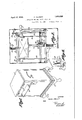
- Fig. 1 is a perspective view showing a suitable configuration of outer casing accommodating the mechanism of the apparatus.
- Fig. 2 is a part sectional front elevation view of the operating mechanism.
- Fig. 3 is a side elevation view of Fig. 2 showing the normal condition of the operating mechanism.
- Fig. 1 is a broken side elevation view showing the first stage of operation of the mechanism.
- ..Fig. 5 is a broken side. elevation view showing the stage in the operations at which the reciprocating tray picks up the uppermost article of the stack of articles.
- Fig. 6 is a detail perspective view showing a suitable device for regulating the movement of the abutment which predetermines the position of the uppermost of the stack of articles, and
- Fig. 7 is a detail sectional elevation view to a larger scale showing a suitable form of friction device for restraining movement of the platform supporting the stack of articles during the delivery of an article.
- the operating mechanism is shown as accommodated in a box-like casing 1 which can be supported on suitable feet 2.
- the various parts of the mechanism receive their operation from a main shaft 3 which is axially rotated in suitable bearings 4 when it is desired to deliver an article from a stack of articles 5.
- the desired rotation of the shaft 3 can be effected by a lever 6 secured at one end to the shaft 3 and carrying a lateral handle 7 at its free end projecting through a slot '8 in the casing 1.
- the stack 5 of books or other articles is supported upon a platform 9 carried by the upper end of a vertical post 10 slidable in a telescopic manner in a fixed sleeve 11 which can be provided with a flange 12 at its lower end whereby it can be bolted to the base of the casing 1.
- a strong coiled compression spring 13 accommodated in the sleeve 11 and also preferably in the post 10 urges the platform 9 with its load of books or other articles 5 upwards against a normally stationary rocate through an opening 16 in the front wall of the casing 1 along guides 17.
- the plate 15 is normally located with its rear edge nearly touching the front edge of the uppermost book or other article 5 and when the shaft 3 is rotated by a rearward movement of the handle 7 the plate 15 is forced beneath the front edge of the uppermost article 17 a and ultimately between such uppermost article and the one immediately beneath it until the plate reaches the position shown in Fig. 5, in which position it supports the uppermost article and has a slight clearance from or only a very light contact with the-article immediately beneath it.
- the shaft is rotated in the reverse direction by returning the handle 7 to its. normal position, when the plate 15 is protruded through the opening 16 so that the book or other article carriedby it can be removed.
- the sliding plate 15 can be op-eratively connected to the shaft3. by a pair of arms 18 extending. from'the shaft and links 19 connecting these arms to lugs 20 depending from the plate 15. i
- the abutment 14 is preferably a block of rubber formed with arcuate edges as shown so that it does not injure" the articles 5 and is fixed to the free end of an arm 21 extend.- ing downwards from the upper end of a crank 22 fixed to a transverse shaft 23 free to rotate in suitable fixed bearings 94.
- the shaft 23 is connected for rotation to the shaft 3 by a crank 25 at one end and a connecting rod 26 pivoted to a crank 27 fixed to the shaft 3.
- the abutment 14 is maintained in contact with the uppermost book. and forced along it to obtain the puckering action as above described for the desired period by forming a lateral projection 28 (see more particularly Fig. 6) on the arm 21, this projection 28 normally residing in juxtaposition to the front edge of a horizontal.
- lateral extension29a of a pawl 29 pivoted to a fixed bracket 30 by a pin 31.
- he pawl 29 is prevented from moving upwardsfrom' its normal position by reason of the engagement of the lateral extension 29a with the lower edge of the bracket 30 consequently when the sliding plate 15 is urged inwards the lateral projection 28Qcarried by the arm 21 must slide under the pawl 29 the time taken for the amount of movement required for the pro-2 jection 28 toclear the paw1-29 beingthat required to enable the plate 15 to enterbetween the .uppermost pair of books 5 after which the projection 28 trips'over the pawl 29 and strikes the lower edge 30a of the brackiet 30 -whichis inclined rearwa-rdly upwards to permit the abutment '14; to rise clear of the,
- Apparatus for delivering articles com-' prising in combination a compartment in which the. articles to be delivered areaccom adaptedin one direction of its movement to be forced between the'uppermost pair of a stackf'of articles to. be delivered whereby the uppermost article becomes supported by the sliding member and in the other direction of its movementto be projected with the-said upperinostlarticle outsidethe container compartment, means for moving the stack of articles a distance equal to the thickness of one article upon each delivery of an article whereby the articles are'successively fed to the plane'at-which they are engaged by said reciprocating member for delivery-outside the said compartment, said means comprising aplatform adapted to support the stack of articles, means adapted toimove the platform to raise the stack, means to prevent movement of the platform during the dis placement of the reciprocating sliding mem ber across the top of the stack, said means comprising -acompression spring, loadedbrake shoe in which its spring is normally extended, .means beingprow'ded' for placing modated
- a partition a platform on one side of saidpartition adapted to support a stack of articles, an abutment adapted to engagethe stack, means for forcing said platform towards the abutment against which the uppermost article on the stack is pressed so asto present one edge to one'edge of the-reciprocating plate, means for forcing said plate between the uppermost pair of articles in a stack of articles supported on said platform in one direction of movement of the plate, and means whereby said abutm'ent is restrained against movement away from the stack until the sliding plate is located between the uppermost pair of articles but is moved clear of the stack of articles thereafter until the plate is returned to deliver the article above it.
- &. Apparatus for delivering articles comprising in combination a compartment or the likein which the articles to be delivered are accommodated, a reciprocating plate slidably mounted to move through a partition, a platform on one side of said partition adapted to support a stack of articles, an abutment adapted to engage the stack, means for forcing said platform towards the abutment against which the uppermost article onthe stack is pressed so as to present one edge to one edge of the reciprocating'plate, means for forcing said plate between the uppermost pair of articles in a stack of articles supported on said platform in one direction of movement of the plate, means whereby said abutment is restrained against movement.
- said means comprising a compression spring loaded brake shoe in which its spring is normally extended, means being provided forplacing said spring under compression automatically upon operation of the apparatus to set the reciprocating plate into action;
- Apparatus for delivering articles comprising in combination a compartment or the like in which the articles to be delivered are accommodated, a reciprocating plate slidably mounted to move through a partition, aplatform on one side of said partition, adapted to support a stack of articles, an abutment adapted to engage the stack, means for forcing said platform towards the abutment against which the uppermost article on the stack is pressed so as to present one edge to one edge of the reciprocating plate, means for forcing said plate between the uppermost pairof articles in a stack of articles sup ported on said platform in one direction of movement of the plate, means whereby said abutment is restrained against movement away from the stack until the sliding plate is located between the uppermost pair of articles but is moved clear ofthe stack of articles thereafter until the plate is returned to deliver the article above it, means to prevent movement of the platform during the displacement of "the reciprocating sliding member across the top of the stack, a shaft connected for rotation to an operatinghandle or other suitable prime mover, which shaft is operatively connected to said
- Apparatus for delivering articles comprising in combination a compartment or the like in which the articles to. be delivered are accommodated, a reciprocating plate slidably mounted to move through a partition, a platform on one side of said partition adapted to support a stack of articles, said platform being carried on the upper end of a post slidable in a fixed guide with which is associated spring means, for urging the platform towards an abutment against which the uppermost article on the stack is pressed so as to present one edge to one edge of the reciprocating plate, means for forcing said plate between the uppermost pair of articles in a stack of articles supported on said platform in one direction of movement of the plate, and means whereby said abutment is restrained against movement away from the stack until the sliding plate is located between the uppermost pair of articles but is moved clear of the stack of articles thereafter until the plate is returned to deliver the article above it.
- Apparatus for delivering articles comprising in combination a compartment or the like in which the articles to be delivered are accommodated, a reciprocating plate slidably mounted to move through a partition, a platform on one side of said partition adapted to support a stack of articles, said platform being carried on the upper end of a post slidable in a fixed guide with which is associated a spring for urging the platform towards an abutment, against which the uppermost article on the stack is pressed so as to present one edge to one edge of the reciprocating plate, means for forcing said plate between the uppermost pair of articles in a stack of articles supported on said platform in one direction of movement of the plate, means to prevent movement of the platform during the location of the reciprocating sliding member across the top of the stack, said means comprising a compression spring loaded brake shoe in which its spring is normally extended, means being provided for placing said spring under compression automatically upon operation of the apparatus to set the reciprocating plate into action, and means whereby said abutment is restrained against movement away from the stack until the sliding plate is located between
- Apparatus for delivering articles comprising in combination a compartment or the like in which the articles to be delivered are accommodated, a reciprocating plate slidably mounted to move through a partition, a platform on one side of said partition adapted to support a stack of articles, an abutment engaging the stack, which is forced thereagainst by a spring acting vertically upwards below the platform, said spring being contained within a telescopic post carrying the platform, the lower part of said post being fixed, a cam carried on a fork secured on the fixed part of the post, a spring loaded brake shoe adapted to be pressed onto the movable part of the post by rotation of the cam to hold the said movable part against movement, means for restraining said abutment against movement until the slidlng plate is in a suitable location, and means for actuating said sliding plate, said cam and said abutment in timed relation.
- Apparatus for delivering articles comprising in combination a compartment or. the like in which the articles to be delivered are accommodated, a reciprocating plate slidably mounted to move through a partition, a platform on one side of said partition adapted to support a stack of articles, an abutment engaging the stack, which is forced thereagainst by a spring acting vertically upwards below the platform, said spring being con- "tained within a telescopic post carrying the platform, the lower part of said post being fixed, a cam carried on a fork secured or formed on the fixed part of the post, a spring loaded brake shoe adapted tobe pressed onto the movable part of the post by rotation of the cam to hold the said movable part against movement, means for restraining said abut-J.
- Apparatus for delivering periodicals,- ncwspapers or like flexible articles comprisingin combination a compartment or the like in which the articles to be 'delivered'are if mover, a reciprocating member to the shaft and carrying the abutment, said reciprocat-' ing member being adapted to be moved in one direction so that a part of it rides over a uiding surface inclined rearwardly away from said platform but containing a relatively movable pawl member over which the said part of the said abutment carrying member rides during the initial movement of the reciprocating plate into the stack of articles, a telescopic, post having a fixed lower portion provided.
Landscapes
- Physics & Mathematics (AREA)
- General Physics & Mathematics (AREA)
- Vending Machines For Individual Products (AREA)
- Sheets, Magazines, And Separation Thereof (AREA)
- Pile Receivers (AREA)
Description
April 12, 1932. PARFETT v APPARATUS FOR DELIVERING ARTICLES Filed Feb. 20, 1950 2 Sheets-Sheet mvgmon FRHHK PHRFETT .54; RHEYS PER April 12, 1932. V PARFETT' 1,853,926
APPARATUS FOR DELIVERING ARTICLES Filed Feb. 20, 1950 2 Sheets-Sheet 2 l w-i-o 34 35.37 3
IN VEN TOR FRfl/IK PHRFEU' PER i? FRANK PARFETT, or Lennon,
of movement being raised to form abutments Patented Apr. 12, 1932 UNITED T TES I a 7 OF LONDON,
ENGLAND AriaAn-Arus F03 DELIVERING ARTICLES 3 Application filed. February e0, 1939, Sean- 0.
The present invention has for its object to provide a simple and reliable mechanism for delivering successively periodicals or the like from an accumulation of them accommodated in a suitable compartment. "The invention can beused with a coin freed mechanism whereby upon the insertion of a predetermincd value of coinage inan appropriate part of the apparatus the mechanism will be freed for delivering one periodical froma stack ofperiodicals within the compartment. f i 1 f My invention is broadly characterized in that the articles to be delivered are accom-. modated in a compartment and are engaged successively by an endless band or a recipro eating sliding member adapted in one direction of its movement to be forced between the uppermost pair of a stack of articles to be delivered whereby the uppermost article becomes supported by the sliding member, and in the other direction of its movement to be projected with the said uppermost article outside the said'compartment, means being provided for moving the stack of articles a distance equal to the thickness ofone article upon each delivery of an article whereby the articles are successivelyfed to theplane at which they are engagedby said reciprocating a member for delivery outsidethesaidcorfi- V partment.
The said reciprocating member is preferably a fiat tray onplaten operating in a horizontal plane and reciprocating through a slot in one wall of said compartment, the edges of the tray parallel with its direction for the corresponding edges of the article be: ing delivered. The compartment may be a box accommodating the whole of the mechanism or it may be constituted by a panel containing' the said slot andlocated in a wall of a bookstall or shopwhere an attendant can readily replenish the stack when required, However, it is preferred for the apparatusto be self-contained. Q I A j The stack of books, folded'newspapers or other articles it" is desired to deliver are mounted in a neatstack upon: the upper surface of a suitableplatform which is mounted 430,007, and in G reatBritain March 2, 1929,
to move upwards-by a succession of shortv movements and for such purpose is guided and loaded in any suitable manner. For instance it can be arranged to slide along vertical guides and be connected by suitable ligatures to adepending weight, or it can be AT NTerFIC ENGLAND, Assrenon or ONE-HALF TO MYER zAne,
carried by a vertical pillar slidable in a telescopic manner in a fixed verticalsleeveac- 'commodating a coiled compressionspring;
urging the pillarjupwards. a V
A suitable abutment normally engaging the uppermost article" of the stack of'articles predetermines the position of the uppermost article and thisabutment is arranged to be" moved automatically at the appropriate moment to enable the reciprocating tray be delivered. Inadvance of, or simultane- 5 ously with'the inward movement of the tray :to engage the uppermost article a suitable device is brought into operation to prevent to slide under theuppermost article to re any movement of the said platform until the said abutment consequent uponthe removal of the uppermost of the articlesjis returned to its normal position, wl 1ereup on theplat form is automaticallyreleased to enable it to move upwards under the influence of the said suspended weight or coiled compression spring until the uppermost article "abuts I "against the said abutment. Thi'sfrestraining devicemay be a friction brake type of device operating on the said 'slidable pillar carrymg the platform and normally out of opera- 7 tion but brought automatically into operation upon the commencement of actuating the apparatus to deliverrthe desired article;
The apparatus can be manually or electrically operated and is preferably provided with any suitable coin release mechanism necessitat ng the insertion of a predeter mined value of coinage before the apparatus can be operated. In, order to avoid compli: V cationsm description -I have refrained from showing a coin release mechanism'or an elec trically operated prime mover as there are available many suitable devices for this purpose.
In order that my invention may be clearly understood and readily carried into effect, I have appended hereto a sheet of drawings illustrating for example a manually oper-' ated self-contained apparatus for successively delivering articles from a stack, and wherein i Fig. 1 is a perspective view showing a suitable configuration of outer casing accommodating the mechanism of the apparatus.
Fig. 2 is a part sectional front elevation view of the operating mechanism.
Fig. 3 is a side elevation view of Fig. 2 showing the normal condition of the operating mechanism.
Fig. 1 is a broken side elevation view showing the first stage of operation of the mechanism.
..Fig. 5 is a broken side. elevation view showing the stage in the operations at which the reciprocating tray picks up the uppermost article of the stack of articles.
Fig. 6 is a detail perspective view showing a suitable device for regulating the movement of the abutment which predetermines the position of the uppermost of the stack of articles, and
Fig. 7 is a detail sectional elevation view to a larger scale showing a suitable form of friction device for restraining movement of the platform supporting the stack of articles during the delivery of an article.
Referring to the drawings the operating mechanism is shown as accommodated in a box-like casing 1 which can be supported on suitable feet 2. The various parts of the mechanism receive their operation from a main shaft 3 which is axially rotated in suitable bearings 4 when it is desired to deliver an article from a stack of articles 5. The desired rotation of the shaft 3 can be effected by a lever 6 secured at one end to the shaft 3 and carrying a lateral handle 7 at its free end projecting through a slot '8 in the casing 1.
. The stack 5 of books or other articles is supported upon a platform 9 carried by the upper end of a vertical post 10 slidable in a telescopic manner in a fixed sleeve 11 which can be provided with a flange 12 at its lower end whereby it can be bolted to the base of the casing 1. A strong coiled compression spring 13 accommodated in the sleeve 11 and also preferably in the post 10 urges the platform 9 with its load of books or other articles 5 upwards against a normally stationary rocate through an opening 16 in the front wall of the casing 1 along guides 17.
The plate 15 is normally located with its rear edge nearly touching the front edge of the uppermost book or other article 5 and when the shaft 3 is rotated by a rearward movement of the handle 7 the plate 15 is forced beneath the front edge of the uppermost article 17 a and ultimately between such uppermost article and the one immediately beneath it until the plate reaches the position shown in Fig. 5, in which position it supports the uppermost article and has a slight clearance from or only a very light contact with the-article immediately beneath it. In order to deliver the article now supported by the plate 15 the shaft is rotated in the reverse direction by returning the handle 7 to its. normal position, when the plate 15 is protruded through the opening 16 so that the book or other article carriedby it can be removed.
The sliding plate 15 can be op-eratively connected to the shaft3. by a pair of arms 18 extending. from'the shaft and links 19 connecting these arms to lugs 20 depending from the plate 15. i
When dealing with periodicals orymagazines their flexibility can be utilized to assist inintroducing: the plate 15 between the up permost pair for which purpose the abutment 14- is forced sli htly downwards and rearwards along the uppermost booknntil the book has puckered up as shown in Fig. 4 a suflicient amount to enable the plate to slide under the uppermost book when the abutment 14 is raised clear of the stack of books as shown in Fig. 5. l
The abutment 14: is preferably a block of rubber formed with arcuate edges as shown so that it does not injure" the articles 5 and is fixed to the free end of an arm 21 extend.- ing downwards from the upper end of a crank 22 fixed to a transverse shaft 23 free to rotate in suitable fixed bearings 94. The shaft 23 is connected for rotation to the shaft 3 by a crank 25 at one end and a connecting rod 26 pivoted to a crank 27 fixed to the shaft 3.
i The abutment 14 is maintained in contact with the uppermost book. and forced along it to obtain the puckering action as above described for the desired period by forming a lateral projection 28 (see more particularly Fig. 6) on the arm 21, this projection 28 normally residing in juxtaposition to the front edge of a horizontal. lateral extension29a of a pawl 29 pivoted to a fixed bracket 30 by a pin 31. he pawl 29 is prevented from moving upwardsfrom' its normal position by reason of the engagement of the lateral extension 29a with the lower edge of the bracket 30 consequently when the sliding plate 15 is urged inwards the lateral projection 28Qcarried by the arm 21 must slide under the pawl 29 the time taken for the amount of movement required for the pro-2 jection 28 toclear the paw1-29 beingthat required to enable the plate 15 to enterbetween the .uppermost pair of books 5 after which the projection 28 trips'over the pawl 29 and strikes the lower edge 30a of the brackiet 30 -whichis inclined rearwa-rdly upwards to permit the abutment '14; to rise clear of the,
uppermost book under theinfluence of a coiled tension spring 32 connected to thearm' plate 15, the lateral projection 28 of the arm 21can slide between the lower edge of the bracket-30 and the pawl 29,, a coiled tension spring 33 ensuring the pawl 29 at the completion of the sequence of operations returned to its normal-position. 7
It is desirable during the operations of" sc lecting and delivering the articles; to prevent any movement of the platform '9 under the influence of the spring 13, but to release the platform for such movement immediately the plate 15 is projected. through .theopening 16 in order to'bring the remaining-uppermost article against the abutment 14; readyfor a recommencement of the sequence'of operations. 7 For this purpose I provide a device withthe sleeve 11 which upon commenc ing to operate, the apparatus is brought into operation to act as a brake on the post 10 to restrain its movement. v The device is more clearly shown in Fig. and consists ofla friction shoe 3% slidable in a radial passage .35 in a collar 36 surrounding the sleeve lland normally engaging the post 10 under the slight pressure of a coiled compression spring 37.
normally in the extended position and located between the shoe 34; and a likeimember 38 carrying a roller v39 disposed between the limbs of a bifurcated extension-4:0 of the col-t [ar 36; The roller 39" is pressed by the spring 37 against a cam like'member 4C1 fixedzin'a spindle 42 mounted across the limbs of the operation the coiled spring37 is set under compression. and the brake shoe 34 applies sufficient ressure against the ost10 to re-v vent it froinmoving during thedesired period. To obtain a quick operation ofathis brake device the cam like member 41 normally presents a straightse mental edge to the roller 39 as shown in Fig. 3, the remainder of the periphery of the member 41 being. cir-v cular and concentric with its spindle 42., Itwill be apparent that the invention can being be adapted to the delivery of packets of articles other than books and the likeparticular- Iy-packets of stationery, handkerchiefs and otherjflcxible articles. 1 a
' I claim:'
i 1. Apparatus for delivering articles com-' prising in combination a compartment in which the. articles to be delivered areaccom adaptedin one direction of its movement to be forced between the'uppermost pair of a stackf'of articles to. be delivered whereby the uppermost article becomes supported by the sliding member and in the other direction of its movementto be projected with the-said upperinostlarticle outsidethe container compartment, means for moving the stack of articles a distance equal to the thickness of one article upon each delivery of an article whereby the articles are'successively fed to the plane'at-which they are engaged by said reciprocating member for delivery-outside the said compartment, said means comprising aplatform adapted to support the stack of articles, means adapted toimove the platform to raise the stack, means to prevent movement of the platform during the dis placement of the reciprocating sliding mem ber across the top of the stack, said means comprising -acompression spring, loadedbrake shoe in which its spring is normally extended, .means beingprow'ded' for placing modated, a reciprocating sliding member said spring, under compression automatically upon operationof the apparatus to set the reciprocating plate into action.
' 2. Apparatus for delivering articles com? prising in combination a compartment or the likein which the articles to be delivered are accommodated, a reciprocating plate'slid- V ably mounted to move through. a partition, a platform on one side of saidpartition adapted to support a stack of articles, an abutment adapted to engagethe stack, means for forcing said platform towards the abutment against which the uppermost article on the stack is pressed so asto present one edge to one'edge of the-reciprocating plate, means for forcing said plate between the uppermost pair of articles in a stack of articles supported on said platform in one direction of movement of the plate, and means whereby said abutm'ent is restrained against movement away from the stack until the sliding plate is located between the uppermost pair of articles but is moved clear of the stack of articles thereafter until the plate is returned to deliver the article above it.
- 3; Apparatus for delivering articles com-V abutment adapted tojeng'age the stack, means for forcing said platform towards the abut I abutment is restrained against movement away from the stack until the sliding plate is located between the uppermost pair of ar ticles but is moved clear of the stack of articles thereafter until the plate is returned to deliver the article above it, and means to prevent movement of the platform during the displacement of the reciprocating sliding member across the top of the stack.
&. Apparatus for delivering articles comprising in combination a compartment or the likein which the articles to be delivered are accommodated, a reciprocating plate slidably mounted to move through a partition, a platform on one side of said partition adapted to support a stack of articles, an abutment adapted to engage the stack, means for forcing said platform towards the abutment against which the uppermost article onthe stack is pressed so as to present one edge to one edge of the reciprocating'plate, means for forcing said plate between the uppermost pair of articles in a stack of articles supported on said platform in one direction of movement of the plate, means whereby said abutment is restrained against movement.
away from the stack until the sliding plate is located between the uppermost pair of articles but is moved clear of the stack of articles thereafter until the plate is returned to deliver the article above it, and means to prevent movement of the platform during the displacement of the reciprocating sliding member across the top of the stack, said means comprising a compression spring loaded brake shoe in which its spring is normally extended, means being provided forplacing said spring under compression automatically upon operation of the apparatus to set the reciprocating plate into action;
5. Apparatus for delivering articles comprising in combination a compartment or the like in which the articles to be delivered are accommodated, a reciprocating plate slidably mounted to move through a partition, aplatform on one side of said partition, adapted to support a stack of articles, an abutment adapted to engage the stack, means for forcing said platform towards the abutment against which the uppermost article on the stack is pressed so as to present one edge to one edge of the reciprocating plate, means for forcing said plate between the uppermost pairof articles in a stack of articles sup ported on said platform in one direction of movement of the plate, means whereby said abutment is restrained against movement away from the stack until the sliding plate is located between the uppermost pair of articles but is moved clear ofthe stack of articles thereafter until the plate is returned to deliver the article above it, means to prevent movement of the platform during the displacement of "the reciprocating sliding member across the top of the stack, a shaft connected for rotation to an operatinghandle or other suitable prime mover, which shaft is operatively connected to said sliding plate, said abutment and said means for preventing movement of the platform.
6. Apparatus for delivering articles comprising in combination a compartment or the like in which the articles to. be delivered are accommodated, a reciprocating plate slidably mounted to move through a partition, a platform on one side of said partition adapted to support a stack of articles, said platform being carried on the upper end of a post slidable in a fixed guide with which is associated spring means, for urging the platform towards an abutment against which the uppermost article on the stack is pressed so as to present one edge to one edge of the reciprocating plate, means for forcing said plate between the uppermost pair of articles in a stack of articles supported on said platform in one direction of movement of the plate, and means whereby said abutment is restrained against movement away from the stack until the sliding plate is located between the uppermost pair of articles but is moved clear of the stack of articles thereafter until the plate is returned to deliver the article above it.
7. Apparatus for delivering articles comprising in combination a compartment or the like in which the articles to be delivered are accommodated, a reciprocating plate slidably mounted to move through a partition, a platform on one side of said partition adapted to support a stack of articles, said platform being carried on the upper end of a post slidable in a fixed guide with which is associated a spring for urging the platform towards an abutment, against which the uppermost article on the stack is pressed so as to present one edge to one edge of the reciprocating plate, means for forcing said plate between the uppermost pair of articles in a stack of articles supported on said platform in one direction of movement of the plate, means to prevent movement of the platform during the location of the reciprocating sliding member across the top of the stack, said means comprising a compression spring loaded brake shoe in which its spring is normally extended, means being provided for placing said spring under compression automatically upon operation of the apparatus to set the reciprocating plate into action, and means whereby said abutment is restrained against movement away from the stack until the sliding plate is located between the uppermost pair of articles but is moved clear of the stack of articles therelike in which the articles to be delivered are accommodated, a reciprocating plate slidably mounted to move through a partition, a plat form on one side of said partition adapted to support a stack of articles, said fplatform being carried on the upper end 0 a post slidable in a fixed guide with which is associated a coiled compression spring for urging the platform towards an abutment against which the uppermost article on the stack is pressed so as to present one edge to one edge of the reciprocating plate, means for forcing said plate between the uppermost pair of articles in a stack supported on said platform in one direction of movement of the plate, means to prevent movement of the platform during the location of the reciprocating sliding member across the topof the stack, said means comprising a compression spring loaded brake shoe in which its spring is normally extended, means being provided for placin said spring under compression automatica 1y upon operation of the apparatus to set the reciprocating plate into action, means whereby said abutment is restrained against movement away from the stack until the sliding plate is located between the uppermost pair of articles but is moved clear of the stack of articles thereafter until the plate is returned to deliver the article above it, a shaft connected for rotation to an operating handle or other suitable prime mover, which shaft is operatively connected to said sliding plate, said abutment and said means for preventing movement of the platform.
9; Apparatus for delivering articles, such as periodicals, newspapers and the like comprising in combination a compartment or the like in which the articles to be delivered are accommodated, a reciprocating plate slidably mounted to move through a partition, a platform on one side of said partition adapted to support a stack of articles, an abutment engaging the stack, which is forced thereagainst by a spring acting vertically upwards below the platform, said spring being contained within a telescopic post carrying the platform, the lower part of said post being fixed, a cam carried on a fork secured on the fixed part of the post, a spring loaded brake shoe adapted to be pressed onto the movable part of the post by rotation of the cam to hold the said movable part against movement, means for restraining said abutment against movement until the slidlng plate is in a suitable location, and means for actuating said sliding plate, said cam and said abutment in timed relation.
10. Apparatus for delivering articles, comprising in combination a compartment or. the like in which the articles to be delivered are accommodated, a reciprocating plate slidably mounted to move through a partition, a platform on one side of said partition adapted to support a stack of articles, an abutment engaging the stack, which is forced thereagainst by a spring acting vertically upwards below the platform, said spring being con- "tained within a telescopic post carrying the platform, the lower part of said post being fixed, a cam carried on a fork secured or formed on the fixed part of the post, a spring loaded brake shoe adapted tobe pressed onto the movable part of the post by rotation of the cam to hold the said movable part against movement, means for restraining said abut-J.
ment against movement until'the sliding plate is in a suitable location, ashaft con-V nected for rotation to an operating'handle, I
which shaft is operatively connected to said sliding plate, said cam and said abutment to operate same in timed relation.
11. Apparatus for delivering periodicals,- ncwspapers or like flexible articles compris ingin combination a compartment or the like in which the articles to be 'delivered'are if mover, a reciprocating member to the shaft and carrying the abutment, said reciprocat-' ing member being adapted to be moved in one direction so that a part of it rides over a uiding surface inclined rearwardly away from said platform but containing a relatively movable pawl member over which the said part of the said abutment carrying member rides during the initial movement of the reciprocating plate into the stack of articles, a telescopic, post having a fixed lower portion provided. with an upwardly acting spring carrying the stack supporting platform, a cam actuated spring pressed brake shoe mounted on the fixed part of said post and adapted to engage the movable part to prevent motion thereof, a lever and'link system to effect the rotation of the cam'upon the rocking of the actuating shaft, and connections to said operating shaft whereby the said sliding plate is reciprocated when the shaft is rocked, whereby the abutment, the sliding plate, the cam, and the stack carrying platform are adapted to move in timed relation. y p
' FRANK PARFETTn
Applications Claiming Priority (1)
| Application Number | Priority Date | Filing Date | Title |
|---|---|---|---|
| GB1853926X | 1929-03-02 |
Publications (1)
| Publication Number | Publication Date |
|---|---|
| US1853926A true US1853926A (en) | 1932-04-12 |
Family
ID=10892022
Family Applications (1)
| Application Number | Title | Priority Date | Filing Date |
|---|---|---|---|
| US430007A Expired - Lifetime US1853926A (en) | 1929-03-02 | 1930-02-20 | Apparatus for delivering articles |
Country Status (1)
| Country | Link |
|---|---|
| US (1) | US1853926A (en) |
Cited By (8)
| Publication number | Priority date | Publication date | Assignee | Title |
|---|---|---|---|---|
| US2478815A (en) * | 1945-02-20 | 1949-08-09 | Forman George Robert | Combination dispensing and bulk reducing device |
| US2501434A (en) * | 1946-05-11 | 1950-03-21 | Daniel D Cameron | Newspaper vending machine |
| US2538238A (en) * | 1943-12-15 | 1951-01-16 | Trevor E Evans | Towel-dispensing apparatus |
| US2612426A (en) * | 1947-06-18 | 1952-09-30 | Clarence L Hawks | Newspaper vending machine |
| US2893596A (en) * | 1953-03-04 | 1959-07-07 | Rowe Mfg Co Inc | Sandwich merchandising machine |
| US2929532A (en) * | 1955-10-03 | 1960-03-22 | Radio Steel & Mfg Co | Mechanism for feeding steel disks or the like |
| US3168212A (en) * | 1962-08-16 | 1965-02-02 | Eric W Edwards | Dispensing apparatus for horizontally disposed articles |
| WO1988000378A1 (en) * | 1986-06-27 | 1988-01-14 | Donald Mathieson Devenish | Newspaper vending machine |
-
1930
- 1930-02-20 US US430007A patent/US1853926A/en not_active Expired - Lifetime
Cited By (8)
| Publication number | Priority date | Publication date | Assignee | Title |
|---|---|---|---|---|
| US2538238A (en) * | 1943-12-15 | 1951-01-16 | Trevor E Evans | Towel-dispensing apparatus |
| US2478815A (en) * | 1945-02-20 | 1949-08-09 | Forman George Robert | Combination dispensing and bulk reducing device |
| US2501434A (en) * | 1946-05-11 | 1950-03-21 | Daniel D Cameron | Newspaper vending machine |
| US2612426A (en) * | 1947-06-18 | 1952-09-30 | Clarence L Hawks | Newspaper vending machine |
| US2893596A (en) * | 1953-03-04 | 1959-07-07 | Rowe Mfg Co Inc | Sandwich merchandising machine |
| US2929532A (en) * | 1955-10-03 | 1960-03-22 | Radio Steel & Mfg Co | Mechanism for feeding steel disks or the like |
| US3168212A (en) * | 1962-08-16 | 1965-02-02 | Eric W Edwards | Dispensing apparatus for horizontally disposed articles |
| WO1988000378A1 (en) * | 1986-06-27 | 1988-01-14 | Donald Mathieson Devenish | Newspaper vending machine |
Similar Documents
| Publication | Publication Date | Title |
|---|---|---|
| US1853926A (en) | Apparatus for delivering articles | |
| US2546352A (en) | Vending machine for newspapers and the like | |
| US1619006A (en) | Coin-controlled vending machine | |
| US1926848A (en) | Vending machine | |
| US1866847A (en) | Mail magazine | |
| US1997078A (en) | Vending machine | |
| US2624647A (en) | Cup dispenser | |
| US1889689A (en) | Dispensing device | |
| US1912999A (en) | Vending machine | |
| US1931741A (en) | Vending machine | |
| US772588A (en) | Automatic indicator for scales | |
| US800072A (en) | Newspaper-vending machine. | |
| US781026A (en) | Vending-machine. | |
| US2010373A (en) | Vending-machine | |
| US1889109A (en) | Vending machine | |
| US754090A (en) | Automatic photographic apparatus. | |
| US676242A (en) | Punching-machine. | |
| GB334497A (en) | Apparatus for delivering newspapers or the like | |
| US1739651A (en) | Card-selector mechanism | |
| US1748914A (en) | Cover-lining apparatus | |
| US551561A (en) | Paper-folding machine | |
| US1488288A (en) | Combined vending and weighing machine | |
| US448200A (en) | Coin-controlled weighing-scale | |
| US820543A (en) | Coin-controlled apparatus. | |
| US1384586A (en) | Vending-machine |