US1853923A - Excavating machine - Google Patents
Excavating machine Download PDFInfo
- Publication number
- US1853923A US1853923A US451321A US45132130A US1853923A US 1853923 A US1853923 A US 1853923A US 451321 A US451321 A US 451321A US 45132130 A US45132130 A US 45132130A US 1853923 A US1853923 A US 1853923A
- Authority
- US
- United States
- Prior art keywords
- tube
- platform
- united
- cutter
- hopper
- Prior art date
- Legal status (The legal status is an assumption and is not a legal conclusion. Google has not performed a legal analysis and makes no representation as to the accuracy of the status listed.)
- Expired - Lifetime
Links
Images


Classifications
-
- E—FIXED CONSTRUCTIONS
- E21—EARTH DRILLING; MINING
- E21C—MINING OR QUARRYING
- E21C27/00—Machines which completely free the mineral from the seam
- E21C27/20—Mineral freed by means not involving slitting
- E21C27/24—Mineral freed by means not involving slitting by milling means acting on the full working face, i.e. the rotary axis of the tool carrier being substantially parallel to the working face
Definitions
- My invention relates to excavating machines.
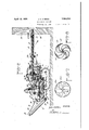
- Figure l is a plan view of my machine, but having a portion of the pipe, 38a, and bearing, 38?) omitted to prevent interferance'
- Figure 2 is a longitudinal section onthe line 22 of Figure 1';
- Figure 3 is an enlarged sectional detail of the driving mechanism for the treads and the rear cutters on the line, 3-3, of Figure 1;
- V v Figure 4 is an enlargedsectional detail showing the jack-shaft and tread drive on the line, 4-4, of Figure 3;
- Figure 5 is an enlarged detailofthe squareshaft and slip joint on the line 5-5 of'F-ig- Figure 6 is an enlargeddetail'of the elevatmg screw
- Figure '7 is an enlarged end view of the forward cutter
- Figure 8 1s a cross-sectional view on the Similar numerals refer to similar parts throughout the several Views.
- My apparatus comprises a main frame composed of longitudinal frame members, fl, and cross-frame members, 4, suitably mounted upon the front axle, 2,-and rear axle, 3.
- Caterpillar treads, 1, are providedmounted upon wheels which in turn are revolvably mounted upon the axles, 2 and 3,-inthe usual Rigidly secured to the main frame is a fixed circular track, 5, of iron or other suit.
- a rotatable frame, 7, is mounted upon the fixed circular track, 5, and is revolvable thereon upon channeled traversing wheels, 6, which are mountedupon brackets, 6a, rigidly secured to the rotatable frame, 7.
- a tilting platform, 12, preferably comprising framing' members with planking suitably secured thereto, has its rear end pivotally mounted upon a pivot shaft, 13, which ex tends transversely ofthe rotatable frame near' the rear end thereof, with spacers, 13a, interposed upon the shaft, 13, between the side the tilting platform, 12.
- the Shaft, 13- may be secured by nuts, 13?), or any other suitable means.
- a screw, 14 has its lower rame members of the rotatable frame, 7, and s internally threaded to correspond to the screw, l gand has a collar, 16a, rigidly secured thereto by a pin, 166, or other suitable means.
- a hand-wheel, 18, is rigidly secured to the top of the sleeve, 16, by a pin, 18, or other suitable means, by means of which the sleeve, 16, may be rotated.
- the screw, 1e, the screw, 14 can move upon its pivot, 14a, to allow the tilting of the screw necesssary to compensate for the movement of the tilting platform, 12.
- the front end of the tilting platform, 12, carries a ball bearing, 23, and a corresponding bearing, 24, is rigidly mounted upon the tilting platform, 12, somewhat to the rear of the elevating screw, 14.
- I mount a rotatable tube, 19, which is secured against longitudinal movement by collars, 23a and 24:65, united to the tube adjacent the ball bearings, 23 and 24.
- a gear, 26, which is rigidly secured to the tube and adapted to be driven by a pinion, 27, mounted upon and clutched to a motor shaft, 29, by a throw-out clutch, 28, which motor shaft extends forwardly from the motor, 30, and may be mounted in suitable bearings of any desired type, secured to the tilting platform, 12.
- the front ends of the spiral cutting members are reenforced and braced by transverse cutters, 20a, which have semi-circular edges, 20b, extending slightly forwardly.
- the spiral cutters, 20, and the cutters, 20a are all united to a central shaft, 200, and the spiral members, 20, have their rear ends secured by bolts, 21a, to the collar, 21, so that as the tube, 19, revolves, it carries with it the cutting member, 20 and 20a.
- a spiral flange, 19a which may be continuous or composed of successive and interrupted flights.
- a hot air blast pipe, 37 is mounted in the center of the tube, 19, the front end of which is supported by the shaft, 200, the rear end of which is secured in a suitable support, 38?), and is connected with a pipe, 38a, to a dust bin, 38.
- This dust bin, 38 is connected by suitable piping, 37, to a blower, 31, in which a fan is mounted upon the shaft, 32, driven by a belt, 34, and belt wheel, 33, from a pulley, 35,- mounted upon the motor shaft, 29.
- An air heater, 36 is mounted upon the rear' of the tilting platform, 12, which may be heated by any suitable means, and an outlet pipe, 366, leads from the heater, 36, to the blower, 31.
- Dust material of any suitable kind may be deposited in the dust bin and this material and the bin are arranged in such a way that the air passing therethrough will carry a small quantity of dust as it passes through the hot air pipe, 37, into the tube, 19, so that theclaypassing through the revolving tube, 19, will not only be dried to some extent by the hot air, but will also be coated to some extent by the dust and the inside of the tube, 19, will likewise be coated by the dust so as to prevent sticking and clogging therein.
- I mount a hopper, 7 4, upon suitable supports, 74a, united to the fixed frame members, 4, which hopper is adaptedto receive the clay as it comes from the tube, 19.
- I mount a series of baffles, 71. Inthe center of the hopper I provide a cutter shaft,
- the rear end of the square shaft, 64 is united to the front member of a universal oint, 63, and to the rear member of the universal joint, 63, is united a shaft, 60a, which carries a bevel gear pinion 60, which in turn meshes with a corresponding pinion, 59, united to the jack-shaft, 43, and the jackshaft, 13, is. mounted in suitable bearings formed in supports, 44, secured to the tilting platform, 12, by bolts, 44a, or other suitable means.
- a throw-out clutch, 62 is mounted upon the shaft, 60a.
- the lower end of the cutter shaft, 7 0, extends through the bottom plate of no the hopper, 74;, and into a gear case, 77, and has ri idly mounted thereon a bevel gear, 75, which meshes with and drives a corresponding gear 7 6, mounted upon the spiral conveyor shaft, 79a, which is revolvably mounted in suitable bearings, 80 and 80a, united to the frame member, 4, in any suitable manner.
- a spiral conveyor plate, 79 which may be continuous or of separate interrupted flights, is united to the conveyor shaft, 79a, within a tube, 78.
- An opening in the bottom ofthe hopper, 74, is provided which leads into the front end of the tube, 78, and is adapted to conduct the material from the hopper, 7 1, into the conveyor.
- an elevator housing, 81 having a belt elevator, 84, traveling therein over rolls, 82 and 83, which are revolvably mounted in the. elevator housing, 81, and from which the in-- ished product may be delivered to a wagon, bin or any other desired receptacle.
- Brace rods, 85 to brace the elevator, are provided having their upper ends connected to the elevator housing, 81, and their lower ends suitably connected to the main frame members, 4.
- the elevator is driven by a drive or sprocket chain, 86, which passes over 7 a sprocket wheel mounted upon the shaft, 82'
- bracket, 88 united to the main frame, 4, and the circular track, 5.
- the caterpillar. treads are driven by the motor, 30, as follows:
- the motor shaft, 29, extends to the rear of the motor and there carries a bevel gear pinion, 41, which meshes with a corresponding pinion, 42, mounted upon the jack-shaft, 43, which is heretofore described as mounted in suitable supports, 44.
- the jack-shaft, 43 has rigidly mounted thereon a sprocket wheel, 45, (see fig. 4) which .rives a chain, 47, and this chain passes over and drives a wheel, 46, having a hub, 46,
- a bevel gear driving pinion, 53 is mounted upon the shaft, 13, with teeth, 53a, adapted to mesh with corresponding teeth formed upon the clutch member 49.
- a corresponding bevel gear, 54 is mounted upon the upper end of the shaft, 55, in mesh with the gear,"53.
- A. gear housing, 54a is provided to enclose the gears, 53 and 54.
- the lower end of the shaft, 55 is mounted in a suitable bearing mounted uponthe housing, 58, surrounding the shaft, 3, and bears a bevel gear pinion, 56, which meshes with a corre? sponding bevel gear pinion, 57, which is rigidly secured to the rotatable frame 7.
- the cutter When desired," the cutter maybe started at one end of the arc, 90, shown in the bank, 89, in Figure 1 or if desired, the clutches to drive the cutters and the caterpillar treads may be operated simultaneously and the cutter head driven directly into the bank; In such cases, the cutting edges and the front blades of the cutters will cut a circular opening right into the bank forthe full length of the head. . The treads may then be stopped and the cutter swung from side to side by the hand-wheel, 11, as heretoforedescribed. p
- My machine has not only the advantage of cutting the clay initially in thin shavings or ribbons which can be much more readily reduced than material mined in chunks, but provides means for dusting the material and the conveyors with dry dust to prevent sticking and concurrent means for drying out the material as it passes through the conveyors.
- the material will accordingly reach the discharge end of the machine in fine particles from which a large percentage of the moisture content has been removed. It will therefore be very much more suitable for further reduction in ball or roller mills or such other machines as may be used for further pulverizing it.
- Any suitable form of motor or engine may be used to drive the cutters, blower, spiral conveyor, elevator and caterpillar treads and a single motor or engine or a plurality of motors and engines may be used for this purpose. So, also, any desired form of heater may be used for heating the air.
- serrated or indented cutting edges may be provided for the spiral cutters which will be well adapted for certain classes of work, but for such materials as the bentonite found in South Dakota, I prefer to use the form of cutters illustrated, as being the best adapted to that particular kind of material.
- An excavating machine comprising a fixed frame mouted upon suitable supporting means, a circular track rigidly secured upon the fixed frame, a rotatable frame rotatably mounted upon the circular track, co-acting means united to the rotatable frame and to the circular track respectively adapted to revolve the rotatable frame upon said track, a platform mounted on the rotatable frame, a plurality of bearings united to the platform, a tube revolvably mounted .in said bearings and extending forwardly therefrom, a cutter-head united to the front end of the tube, means mounted upon the platform adapted to rotate the tube and the cutter-head carried thereby, a hopper secured frame and to the circular track respectively to the platform, a tube revolvably mounted in said bearings and extending forwardly therefrom, a cutter-head united to the front end of the tube, means mounted upon the platform adapted to rotate the tube and the cutter-head carried thereby, a hopper secured to the fixed frame under the rear end of the tube, a plurality of
- An excavating machine comprising a fixed frame mounted upon suitable supporting means, a circular track rigidly secured upon the fixed frame, a rotatable frame rotatably mounted upon the circular track, coacting means united to the rotatable frame and to the circular track respectively adapted to revolve the rotatable frame upon said track, a platform mounted on the rotatable frame, a plurality of bearings united to the platform, a tube revolvably mounted in said bearings and extending forwardly therefrom, a cutter-head united to the front end of the tube, means mounted upon the platform adapted to rotate the tube and the cutter-head carried thereby, a hopper secured to the fixed frame under the rear end of the tube, a plurality of baflles and a revolving cutter mounted in the hopper and a spiral conveyor mounted upon the fixed frame adjacent the hopper and adapted to carry away the material from the hopper.
- An excavating machine comprising a fixed frame mounted upon suitable support ing means, a circular track rigidly secured upon the fixed frame, a rotatable frame rotatably mounted upon the circular track, coacting means united to the rotatable frame and to the circular track respectively adapted to revolve the rotatable frame upon said track, a platform mounted on the rotatable frame, a plurality of bearings united to the platform, a tube revolvably mounted in said bearings and extending forwardly therefrom, a cutter-head united to the front end of tie tube, means mounted upon the platform adapted to rotate the tube and cutter-head carried thereby, a pipe secured centrally of thetube and having ports opening into the tube, a dust bin, a connecting pipe from the bin to the pipe in the tube, and means to blow dust from the bin through the pipes and into the tube.
- An excavating machine comprising a fixed frame mounted upon suitable supporting means, a circular track rigidly secured upon the fixed frame, a rotatable frame rotatably mounted upon the circular track, co-acting means united to the rotatable frame and to the circular track respectively adapted to revolve the rotatable frame upon said track, a platform mounted on the rotatable frame, a plurality of bearings united to the platform, a tube revolvably mounted in said bearings and extending forwardly therefrom,
- An excavating machine comprising a fixed frame mounted upon suitable supporting means, a circular track rigidly secured upon the fixed frame, a rotatable frame rotatably mounted upon the circular track, co acting means united to the rotatable frame,
- a platform mounted on the rotatable frame, a plurality of bearings united to the platform, a tube revolvably mounted in said bearings and extending forwardly therefrom, a cutter-head united to the front end of the tube, means mountedupon the platform adapted to rotatethe tube and the cutter-head carried thereby, a hopper secured to the fixed frame under the rear end of the tube, a revolving cutter mounted in the hopper, a conveyor mounted upon the fixed frame adjacent the hopper and adapted to carry away the material from the hopper, a pipe secured centrally of the tube and having ports opening into the tube, a dust bin, a connect-1 ing pipe from the bin to the pipe in the tube,
- An excavating machine comprising a fixed frame mounted upon suitable supporting means, a circular track rigidly secured upon the fixed frame, a rotatable frame rotatably mounted upon the circular track,- coacting means united to the rotatable frame and toth e circular'track respectively adapted; to revolve the rotatable frame upon said track, a platform mounted on the rotatable "frame, a plurality of bearings united tothe platform, a tube revolvablymountedin said bearings and extending forwardly therefrom, :a cutter-head united to the front end vof the tube, means-mounted upon the platform-adapted to-rotate the tube and'the cutter-headcarried thereby, a hopper secured to the fixed frame under the rearendyof the tube, arevolving-cutter mounted inthe' hopiper, aconveyor mounted upon the fixed frame adjacent the hopper and adapted to carry away the material from-the hopper, an air heater. mounted upon the platform and means for conductingheated air therfrom into the tube.
- Y lOgAn excavating machine comprising a fixed frame mounted upon suitable supporting means, a circular track rigidly secured upon'the fixed frame, a rotatable frame rotatably mounted upon the circular trackjcoe acting means united to the rotatable frame and to the circular track respectively adapted to revolve therotatable frame uponsaid" track, a platform mounted on'the rotatable frame, a plurality of bearings united tothe platform, a tube revolvably' mounted in said bearings and extending forwardly therefrom, a cutter-head united to thefront end of i the tube, means mounted upon the platform adapted to rotate the tube and the cutterhead carried thereby, a hopper secured-to the fixed frame under the rear end of the tube,- a
- baffles and a revolving cutter mounted in the hopper, a conveyor mounted upon the fixed frame adjacent the hopper and adapted to carry away the material from the hopper and an elevator adapted to receive and discharge at a height, the material carried from the hopper by the conveyor.
- An excavating machine comprising a fixed frame mounted upon suitable supporting means, a tiltable platform united to the fixed frame, bearings united to the platform, a conveyor tube revolvably mounted in said bearings and extending forwardly therefrom, a rotary cutter united to the front end of the tube, and means mounted upon the platform adapted torotate the tube and the rotary cutter carried thereby.
- An excavating machine comprising a fixed frame mounted upon suitable support ing means, a movable platform rotatably and tiltably mounted upon the fixed frame, a plurality of bearings united to the movable platform, a conveyor tube revolvably mounted in said bearings and extending forwardly therefrom, a cutter-head united to the front end of the conveyor tube and adapted to excavate the desired material in thin ribbons or shavings, means to rotate the tube and cutter-head and means to subject the excavated material to the action of a blast of hot air while passing through the conveyor tube.
- An excavating machine comprising a fixed frame mounted upon suitable supporting means, a movable platform rotatably and tiltably mounted upon the fixed frame, a plurality of bearings united to the movable plat form, a conveyor tube revolvably mounted in said bearings and extending forwardly therefrom, a cutter-head united to the front end of the conveyor tube and adapted 'to excavate the desired material in thin ribbons or shavings, means to rotate the tube and cutterhead, means to subject the excavated material to the action of ablast of hot air while passing through the conveyor tube, and auxiliary means for comminuting or pulverizing the excavated material after it leaves the conveyor tube.
Description
April 12, 1932. J. H. OBRIEN EXCAVATING MACHINE Filed May 10, 1930 5 She ets-Shbet Q Q 673a INVENTOR.
A TTORNEY J. Hv OBRIEN April 12, 1932.
EXCAVATING MACHINE 3 Sheet s-Sheet 2 Filed May '10, 1930 IN VEN TOR.
A TTORNE Y MEL April 12, 1932. J. H. OBRIEN IEXCAVATING umcnnm 3 Sheets-Sheet Filed May 10 1930 A TTORNEY I nomically mine clay and other earthy min-" lme, 8-8, of Flgure 2.
Patented Apr. I2, 1932 I JOHN H. O'BRIEN, OFZOfiAGEQIWYOll/IING ExcAvArIive MACHEENE I Application filed. ay- 10, 1930., serial no, 451,321.
My invention relates to excavating machines.
The objects of my invention are:
1. To, provide a machine which w1ll eco'-- 2. To provide an apparatus which will successfully operate upon clay and s milar earthy minerals carrying a large moisture content; r
'3. To provide a machine which \Vlll mine moist clay and similar earth minerals, and grind, disintegrate or comminute the exca vated material; g l. To provide a machine whichwill mine moist clay and similar earthy minerals, and grind, disintegrate, 'comminute and dr-yout the excavated material; a 5. In a machine for mining moist clay, to
' provide means for conveying the clay to an elevator'and preventing the sticking of while being conveyed;
6. To provide a mining machine with a A cutter head movable both horizontally and vertically and laterally;
Y 7. To provide a mining machine for the purposes mentioned which can move about under itsrown power; J r 8. To provide a mining machine wh ch will be capable of progressing and cutting both forwardly and laterally. I t 7 I attain these objects by the means illus-- trated in the accompanying drawings, in which,
Figure l is a plan view of my machine, but having a portion of the pipe, 38a, and bearing, 38?) omitted to prevent interferance' Figure 2 is a longitudinal section onthe line 22 of Figure 1';
Figure 3 is an enlarged sectional detail of the driving mechanism for the treads and the rear cutters on the line, 3-3, of Figure 1; V v Figure 4 is an enlargedsectional detail showing the jack-shaft and tread drive on the line, 4-4, of Figure 3;
Figure 5 is an enlarged detailofthe squareshaft and slip joint on the line 5-5 of'F-ig- Figure 6 is an enlargeddetail'of the elevatmg screw V Figure '7 is an enlarged end view of the forward cutter; I
Figure 8 1s a cross-sectional view on the Similar numerals refer to similar parts throughout the several Views.
My apparatus comprises a main frame composed of longitudinal frame members, fl, and cross-frame members, 4, suitably mounted upon the front axle, 2,-and rear axle, 3. Caterpillar treads, 1, are providedmounted upon wheels which in turn are revolvably mounted upon the axles, 2 and 3,-inthe usual Rigidly secured to the main frame is a fixed circular track, 5, of iron or other suit.-
able material, and having an internal ring gear, 5a, united thereto. A rotatable frame, 7, is mounted upon the fixed circular track, 5, and is revolvable thereon upon channeled traversing wheels, 6, which are mountedupon brackets, 6a, rigidly secured to the rotatable frame, 7. V
A tilting platform, 12, preferably compris ing framing' members with planking suitably secured thereto, has its rear end pivotally mounted upon a pivot shaft, 13, which ex tends transversely ofthe rotatable frame near' the rear end thereof, with spacers, 13a, interposed upon the shaft, 13, between the side the tilting platform, 12. The Shaft, 13-, may be secured by nuts, 13?), or any other suitable means.
' The front end ofthe platform, 12, rests normally upon the front'crossamembers of the rotatable frame, 7. A screw, 14, has its lower rame members of the rotatable frame, 7, and s internally threaded to correspond to the screw, l gand has a collar, 16a, rigidly secured thereto by a pin, 166, or other suitable means. A hand-wheel, 18, is rigidly secured to the top of the sleeve, 16, by a pin, 18, or other suitable means, by means of which the sleeve, 16, may be rotated. As the sleeve, 16, rotates in one direction upon the screw, 14, it will carry the front of the tilting platform upwardly away from the rotatable frame, 7, and as it is rotated in the other direction, it will lower the tilting platform, 12, until it rests upon the rotatable frame, 7.
As the front end of the tilting platform is raised by the sleeve, 16, and the screw, 1e, the screw, 14, can move upon its pivot, 14a, to allow the tilting of the screw necesssary to compensate for the movement of the tilting platform, 12.
The front end of the tilting platform, 12, carries a ball bearing, 23, and a corresponding bearing, 24, is rigidly mounted upon the tilting platform, 12, somewhat to the rear of the elevating screw, 14.
Within these ball bearings, I mount a rotatable tube, 19, which is secured against longitudinal movement by collars, 23a and 24:65, united to the tube adjacent the ball bearings, 23 and 24.
At the rear of the tube, 19, I mount a gear, 26, which is rigidly secured to the tube and adapted to be driven by a pinion, 27, mounted upon and clutched to a motor shaft, 29, by a throw-out clutch, 28, which motor shaft extends forwardly from the motor, 30, and may be mounted in suitable bearings of any desired type, secured to the tilting platform, 12.
I thread the front end of the tube, 19, with threads, 22, and mount thereon a cutter collar, 21, to which spiral cuttting members, 20, are secured by bolts, 21a. The cutting members, 20, have their advancing edges, 20, sharpened and inclined slightly outwardly.
The front ends of the spiral cutting members are reenforced and braced by transverse cutters, 20a, which have semi-circular edges, 20b, extending slightly forwardly. The spiral cutters, 20, and the cutters, 20a, are all united to a central shaft, 200, and the spiral members, 20, have their rear ends secured by bolts, 21a, to the collar, 21, so that as the tube, 19, revolves, it carries with it the cutting member, 20 and 20a.
Inside of the tube, 19, and rigidly secured thereto, I mount a spiral flange, 19a, which may be continuous or composed of successive and interrupted flights.
A hot air blast pipe, 37, is mounted in the center of the tube, 19, the front end of which is supported by the shaft, 200, the rear end of which is secured in a suitable support, 38?), and is connected with a pipe, 38a, to a dust bin, 38.
This dust bin, 38, is connected by suitable piping, 37, to a blower, 31, in which a fan is mounted upon the shaft, 32, driven by a belt, 34, and belt wheel, 33, from a pulley, 35,- mounted upon the motor shaft, 29.
An air heater, 36, is mounted upon the rear' of the tilting platform, 12, which may be heated by any suitable means, and an outlet pipe, 366, leads from the heater, 36, to the blower, 31. Dust material of any suitable kind may be deposited in the dust bin and this material and the bin are arranged in such a way that the air passing therethrough will carry a small quantity of dust as it passes through the hot air pipe, 37, into the tube, 19, so that theclaypassing through the revolving tube, 19, will not only be dried to some extent by the hot air, but will also be coated to some extent by the dust and the inside of the tube, 19, will likewise be coated by the dust so as to prevent sticking and clogging therein.
To the rear of and under the tube, 19, I mount a hopper, 7 4, upon suitable supports, 74a, united to the fixed frame members, 4, which hopper is adaptedto receive the clay as it comes from the tube, 19. In this hopper, I mount a series of baffles, 71. Inthe center of the hopper I provide a cutter shaft,
70, the upper end of which extends into a gear case, 69, and has rigidly mounted thereon a bevel gear, 68, which meshes with a corresponding gear, 67, mounted upon the front member of a universal joint, 66, which in turn is united to a square sleeve, 65, which surrounds a square shaft, 64:, and provides a slip joint therewith. The rear end of the square shaft, 64, is united to the front member of a universal oint, 63, and to the rear member of the universal joint, 63, is united a shaft, 60a, which carries a bevel gear pinion 60, which in turn meshes with a corresponding pinion, 59, united to the jack-shaft, 43, and the jackshaft, 13, is. mounted in suitable bearings formed in supports, 44, secured to the tilting platform, 12, by bolts, 44a, or other suitable means.
A throw-out clutch, 62, is mounted upon the shaft, 60a. The lower end of the cutter shaft, 7 0, extends through the bottom plate of no the hopper, 74;, and into a gear case, 77, and has ri idly mounted thereon a bevel gear, 75, which meshes with and drives a corresponding gear 7 6, mounted upon the spiral conveyor shaft, 79a, which is revolvably mounted in suitable bearings, 80 and 80a, united to the frame member, 4, in any suitable manner. A spiral conveyor plate, 79, which may be continuous or of separate interrupted flights, is united to the conveyor shaft, 79a, within a tube, 78. An opening in the bottom ofthe hopper, 74, is provided which leads into the front end of the tube, 78, and is adapted to conduct the material from the hopper, 7 1, into the conveyor.
Upon the shaft, 70, I mount a spider, 73. which is rigidly secured to the shaft, 7 O, and carries cutter blades, 72, adapted to-revolve with the shaft, 70.
As the material passes into the hopper, 74,
. tube, 78. At the rear of the conveyor tube, I
mount an elevator housing, 81, having a belt elevator, 84, traveling therein over rolls, 82 and 83, which are revolvably mounted in the. elevator housing, 81, and from which the in-- ished product may be delivered to a wagon, bin or any other desired receptacle.
Brace rods, 85, to brace the elevator, are provided having their upper ends connected to the elevator housing, 81, and their lower ends suitably connected to the main frame members, 4. The elevator is driven by a drive or sprocket chain, 86, which passes over 7 a sprocket wheel mounted upon the shaft, 82'
of the roll 82, and is in turn driven by a pulley or sprocket wheel, 87, mounted upon the shaft, 87", of the motor, 87. The motor, 87,
is mounted upon a bracket, 88, united to the main frame, 4, and the circular track, 5.
The caterpillar. treads are driven by the motor, 30, as follows: The motor shaft, 29, extends to the rear of the motor and there carries a bevel gear pinion, 41, which meshes with a corresponding pinion, 42, mounted upon the jack-shaft, 43, which is heretofore described as mounted in suitable supports, 44. The jack-shaft, 43, has rigidly mounted thereon a sprocket wheel, 45, (see fig. 4) which .rives a chain, 47, and this chain passes over and drives a wheel, 46, having a hub, 46,
formed integral therewith and loosely mounted upon the shaft, 13, with clutch teeth, 46a, formed on the hub, 46, and with a sliding clutch member, 49, mounted upon the shaft, 13, adjacent the hub, 46, with throw-out lever, 50, pivotal-1y mounted upon a bracket 51, and having a fork formed upon its lower end as shown in Figure 4, which embraces the clutch member, 49.
A bevel gear driving pinion, 53, is mounted upon the shaft, 13, with teeth, 53a, adapted to mesh with corresponding teeth formed upon the clutch member 49.
A corresponding bevel gear, 54, is mounted upon the upper end of the shaft, 55, in mesh with the gear,"53. A. gear housing, 54a, is provided to enclose the gears, 53 and 54. The lower end of the shaft, 55, is mounted in a suitable bearing mounted uponthe housing, 58, surrounding the shaft, 3, and bears a bevel gear pinion, 56, which meshes with a corre? sponding bevel gear pinion, 57, which is rigidly secured to the rotatable frame 7. Upon the upper end of the shaft, 10, I fashion a hand-wheel, 11, by which the same can be manually turned. y
In the operation ofmy machine, it can be driven up to the clay bank, 89, by starting the motor, 30, and throwing in the clutches, 40 and 49. When it has reached the desired position, the clutch, 49, may be thrown out and the clutches, 63 and 28, thrown into engagement. The clutch, 28, will cause the tube,-
- 19, and the cutters, 20, to revolve and the rotatable frame, 7 may then be turned by the hand-wheel, 11, the shaft, 10, and gearing connected thereto so as to carry the cutters through the are described in Figure 1. As the clay is out in thin ribbons by these cuttersit is carried backward by the spiral flights of the tube, 19, to the hopper, 7 4, in the meantime being dried out by the air blast and to some. extent coated by the dust coming through the pipe, 37, and as it passes through this conveyor, it will be broken up by being. tossed around therein. After it passes into the hopper, 7 4, it will be still further comminuted by the cutters and bafiies andthe process will continue as it moves through the spiral conveyor housing, '7 8, to the elevator. At the same time that the motor is started, the blower, 31, is started by the belt,34, so as to produce a blast of air through the heat er, 36, and to the dust bin, 38.
When one horizontal out has been given through the bank, 89, the wheel, 18, maybe turned and the tilting platform, 12,. raised. The cutters thereby will be raised so as to bite into a new path through the clay bank and thisprocess may be continued until all of the clay available to a single setting of the machine has been mined.
When desired," the cutter maybe started at one end of the arc, 90, shown in the bank, 89, in Figure 1 or if desired, the clutches to drive the cutters and the caterpillar treads may be operated simultaneously and the cutter head driven directly into the bank; In such cases, the cutting edges and the front blades of the cutters will cut a circular opening right into the bank forthe full length of the head. .The treads may then be stopped and the cutter swung from side to side by the hand-wheel, 11, as heretoforedescribed. p
When the cutter has been in operation long enough for the clay to bQCRITlGCl' back to'the foot of the elevator, 81, the elevator motor,
7 87, should be started and the hopper wagon driven up to receive the clay as it passes from 1 the elevator.
In the machines heretofore used for mining clay and earthy minerals such as bentonite, great diiiiculty has been experienced when the material contained 'a large percentage of moisture because of the tendency to stick and it has been found very difiiculttopulverize such moist material by any of the 1 means commonly in use for that purpose;
My machine has not only the advantage of cutting the clay initially in thin shavings or ribbons which can be much more readily reduced than material mined in chunks, but provides means for dusting the material and the conveyors with dry dust to prevent sticking and concurrent means for drying out the material as it passes through the conveyors. The material will accordingly reach the discharge end of the machine in fine particles from which a large percentage of the moisture content has been removed. It will therefore be very much more suitable for further reduction in ball or roller mills or such other machines as may be used for further pulverizing it.
Any suitable form of motor or engine may be used to drive the cutters, blower, spiral conveyor, elevator and caterpillar treads and a single motor or engine or a plurality of motors and engines may be used for this purpose. So, also, any desired form of heater may be used for heating the air.
I do not limit my claims to any precise form of motor, heater, cutters or conveyors, for it is obvious that many of these parts may be varied by the substitution of well-known equivalents without departing from the spirit of my invention.
When desired, serrated or indented cutting edges may be provided for the spiral cutters which will be well adapted for certain classes of work, but for such materials as the bentonite found in South Dakota, I prefer to use the form of cutters illustrated, as being the best adapted to that particular kind of material.
I claim:
1. An excavating machine comprising a fixed frame mouted upon suitable supporting means, a circular track rigidly secured upon the fixed frame, a rotatable frame rotatably mounted upon the circular track, co-acting means united to the rotatable frame and to the circular track respectively adapted to revolve the rotatable frame upon said track, a platform mounted on the rotatable frame, a plurality of bearings united to the platform, a tube revolvably mounted .in said bearings and extending forwardly therefrom, a cutter-head united to the front end of the tube, means mounted upon the platform adapted to rotate the tube and the cutter-head carried thereby, a hopper secured frame and to the circular track respectively to the platform, a tube revolvably mounted in said bearings and extending forwardly therefrom, a cutter-head united to the front end of the tube, means mounted upon the platform adapted to rotate the tube and the cutter-head carried thereby, a hopper secured to the fixed frame under the rear end of the tube, a plurality of baffles and a revolving cutter mounted in the hopper, and a conveyor mounted upon the fixed frame adjacent the hopper and adapted to carry away the material from the hopper.
3. An excavating machine comprising a fixed frame mounted upon suitable supporting means, a circular track rigidly secured upon the fixed frame, a rotatable frame rotatably mounted upon the circular track, coacting means united to the rotatable frame and to the circular track respectively adapted to revolve the rotatable frame upon said track, a platform mounted on the rotatable frame, a plurality of bearings united to the platform, a tube revolvably mounted in said bearings and extending forwardly therefrom, a cutter-head united to the front end of the tube, means mounted upon the platform adapted to rotate the tube and the cutter-head carried thereby, a hopper secured to the fixed frame under the rear end of the tube, a plurality of baflles and a revolving cutter mounted in the hopper and a spiral conveyor mounted upon the fixed frame adjacent the hopper and adapted to carry away the material from the hopper.
4. An excavating machine comprising a fixed frame mounted upon suitable support ing means, a circular track rigidly secured upon the fixed frame, a rotatable frame rotatably mounted upon the circular track, coacting means united to the rotatable frame and to the circular track respectively adapted to revolve the rotatable frame upon said track, a platform mounted on the rotatable frame, a plurality of bearings united to the platform, a tube revolvably mounted in said bearings and extending forwardly therefrom, a cutter-head united to the front end of tie tube, means mounted upon the platform adapted to rotate the tube and cutter-head carried thereby, a pipe secured centrally of thetube and having ports opening into the tube, a dust bin, a connecting pipe from the bin to the pipe in the tube, and means to blow dust from the bin through the pipes and into the tube.
5. An excavating machine comprising a fixed frame mounted upon suitable supporting means, a circular track rigidly secured upon the fixed frame, a rotatable frame rotatably mounted upon the circular track, co-acting means united to the rotatable frame and to the circular track respectively adapted to revolve the rotatable frame upon said track, a platform mounted on the rotatable frame, a plurality of bearings united to the platform, a tube revolvably mounted in said bearings and extending forwardly therefrom,
acting means united to the rotatable frame and tothe circular track respectively adapted to revolve the rotatable frame upon said track, a platform mounted on the rotatable frame, a plurality of bearings united to the platform, a tube revolvably mounted in said bearings and extending forwardly therefrom, a cutter-head unitedtothe front end of the tube, means mounted upon the platform adapted to rotate the tube and the cutter-head carried thereby, a pipe secured centrally of the tube and having ports opening into the tube, a dust bin, a-connecting pipe from the bin to the pipe in the tube, an air heater mounted uponthe platform and means for conducting heated air therefrom to the dust bin and thence into the pipes and tube.
7. An excavating machine comprising a fixed frame mounted upon suitable supporting means, a circular track rigidly secured upon the fixed frame, a rotatable frame rotatably mounted upon the circular track, co acting means united to the rotatable frame,
and to the circular track respectively adapted to revolve the rotatable frame upon said track, a platform mounted on the rotatable frame, a plurality of bearings united to the platform, a tube revolvably mounted in said bearings and extending forwardly therefrom, a cutter-head united to the front end of the tube, means mountedupon the platform adapted to rotatethe tube and the cutter-head carried thereby, a hopper secured to the fixed frame under the rear end of the tube, a revolving cutter mounted in the hopper, a conveyor mounted upon the fixed frame adjacent the hopper and adapted to carry away the material from the hopper, a pipe secured centrally of the tube and having ports opening into the tube, a dust bin, a connect-1 ing pipe from the bin to the pipe in the tube,
and meansto bloW dust from the bin through the pipes and into the tube. V
8. An excavating machine comprising a fixed frame mounted upon suitable supporting means, a circular track rigidly secured upon the fixed frame, a rotatable frame rotatably mounted upon the circular track,- coacting means united to the rotatable frame and toth e circular'track respectively adapted; to revolve the rotatable frame upon said track, a platform mounted on the rotatable "frame, a plurality of bearings united tothe platform, a tube revolvablymountedin said bearings and extending forwardly therefrom, :a cutter-head united to the front end vof the tube, means-mounted upon the platform-adapted to-rotate the tube and'the cutter-headcarried thereby, a hopper secured to the fixed frame under the rearendyof the tube, arevolving-cutter mounted inthe' hopiper, aconveyor mounted upon the fixed frame adjacent the hopper and adapted to carry away the material from-the hopper, an air heater. mounted upon the platform and means for conductingheated air therfrom into the tube.
x 9.- An rexcavating' machine comprising a fixed 'frame mounte'rilv upon suitable .supportk upon the fixed frame, a rotatable frame rotatably mounted upon the circular track, coacting'means united to therotatable frame and to the circular track respectivelyiadapte'd -to revolve the rotatable frame uponv said track, a platform.mounted' on the rotatable frame, a plurality of bearings united to the platform,a tuberevolvably mounted in said (P bearings and extending forwardly therefrom, a cutter-head unitedto the front end of the ing. means, a circular track rigidly secured tube, means mounted upon the CplltfGI'Hl adaptedto rotate the tube and the, cutterhead carriedtherebya hopper secured to the fixed frame vunder the rear end of the tube, a
revolving cutter mounted in the hopper,'and
a conveyor mounted upon the fixed frame.
adjacent 713118 hopper and adapted to carry away the material from 'the hopper, a pipe secured centrally of the tube and having ports opening intothe-tube, a dust bin, a connecting pipe from the bin to the pipe in the tube, an air heater mounted uponv the platform and means for conducting heated air therefrom to the dustbin and thence into the'pipes and tube. Y lOgAn excavating; machine comprising a fixed frame mounted upon suitable supporting means, a circular track rigidly secured upon'the fixed frame, a rotatable frame rotatably mounted upon the circular trackjcoe acting means united to the rotatable frame and to the circular track respectively adapted to revolve therotatable frame uponsaid" track, a platform mounted on'the rotatable frame, a plurality of bearings united tothe platform, a tube revolvably' mounted in said bearings and extending forwardly therefrom, a cutter-head united to thefront end of i the tube, means mounted upon the platform adapted to rotate the tube and the cutterhead carried thereby, a hopper secured-to the fixed frame under the rear end of the tube,- a
plurality of baffles and a revolving cutter mounted in the hopper,a conveyor mounted upon the fixed frame adjacent the hopper and adapted to carry away the material from the hopper and an elevator adapted to receive and discharge at a height, the material carried from the hopper by the conveyor.
11. An excavating machine comprising a fixed frame mounted upon suitable supporting means, a tiltable platform united to the fixed frame, bearings united to the platform, a conveyor tube revolvably mounted in said bearings and extending forwardly therefrom, a rotary cutter united to the front end of the tube, and means mounted upon the platform adapted torotate the tube and the rotary cutter carried thereby.
12. The process of mining bentonite and earthy materials containing a considerable proportion of moisture, comprising cutting same from the bank in thin ribbons or shavings, conveying the cuttings through a tube and subjecting them to a blast of hot air while passing through the tube.
13. The process of mining bentonite and earthy materials containing a considerable proportion of moisture, comprising cutting same from the bank in thin ribbons or shavings, conveying the cuttings through a tube and subjecting them to a blast of hot air cairying dry dust, while passing through the tu e.
14:;An excavating machine comprising a fixed frame mounted upon suitable support ing means, a movable platform rotatably and tiltably mounted upon the fixed frame, a plurality of bearings united to the movable platform, a conveyor tube revolvably mounted in said bearings and extending forwardly therefrom, a cutter-head united to the front end of the conveyor tube and adapted to excavate the desired material in thin ribbons or shavings, means to rotate the tube and cutter-head and means to subject the excavated material to the action of a blast of hot air while passing through the conveyor tube.
15. An excavating machine comprising a fixed frame mounted upon suitable supporting means, a movable platform rotatably and tiltably mounted upon the fixed frame, a plurality of bearings united to the movable plat form, a conveyor tube revolvably mounted in said bearings and extending forwardly therefrom, a cutter-head united to the front end of the conveyor tube and adapted 'to excavate the desired material in thin ribbons or shavings, means to rotate the tube and cutterhead, means to subject the excavated material to the action of ablast of hot air while passing through the conveyor tube, and auxiliary means for comminuting or pulverizing the excavated material after it leaves the conveyor tube. V
In testimony whereof he afiixes his signa ture.
JOHN H. OBRIEN.
Priority Applications (1)
| Application Number | Priority Date | Filing Date | Title |
|---|---|---|---|
| US451321A US1853923A (en) | 1930-05-10 | 1930-05-10 | Excavating machine |
Applications Claiming Priority (1)
| Application Number | Priority Date | Filing Date | Title |
|---|---|---|---|
| US451321A US1853923A (en) | 1930-05-10 | 1930-05-10 | Excavating machine |
Publications (1)
| Publication Number | Publication Date |
|---|---|
| US1853923A true US1853923A (en) | 1932-04-12 |
Family
ID=23791751
Family Applications (1)
| Application Number | Title | Priority Date | Filing Date |
|---|---|---|---|
| US451321A Expired - Lifetime US1853923A (en) | 1930-05-10 | 1930-05-10 | Excavating machine |
Country Status (1)
| Country | Link |
|---|---|
| US (1) | US1853923A (en) |
Cited By (3)
| Publication number | Priority date | Publication date | Assignee | Title |
|---|---|---|---|---|
| US2836408A (en) * | 1956-03-28 | 1958-05-27 | Joy Mfg Co | Rotary cutting, core breaking and conveying means |
| DE1145105B (en) * | 1953-02-02 | 1963-03-07 | United Electric Coal Companies | Excavator |
| US5304032A (en) * | 1991-07-22 | 1994-04-19 | Bosna Alexander A | Abradable non-metallic seal for rotating turbine engines |
-
1930
- 1930-05-10 US US451321A patent/US1853923A/en not_active Expired - Lifetime
Cited By (3)
| Publication number | Priority date | Publication date | Assignee | Title |
|---|---|---|---|---|
| DE1145105B (en) * | 1953-02-02 | 1963-03-07 | United Electric Coal Companies | Excavator |
| US2836408A (en) * | 1956-03-28 | 1958-05-27 | Joy Mfg Co | Rotary cutting, core breaking and conveying means |
| US5304032A (en) * | 1991-07-22 | 1994-04-19 | Bosna Alexander A | Abradable non-metallic seal for rotating turbine engines |
Similar Documents
| Publication | Publication Date | Title |
|---|---|---|
| US2756037A (en) | Mining machines having oppositely rotating boring heads | |
| US3308563A (en) | Danek snow removing apparatus | |
| US2132790A (en) | Apparatus for snow removal | |
| US1240481A (en) | Process of and machine for treating earthy material. | |
| US1853923A (en) | Excavating machine | |
| US1462997A (en) | Tunneling machine | |
| US2257637A (en) | Machine for resurfacing oilsurfaced roads | |
| US1319936A (en) | Machine fok | |
| US1482904A (en) | Road-surfacing machine | |
| US2387423A (en) | Snow-removal apparatus | |
| US1398195A (en) | Excavating-machine | |
| US2024551A (en) | Snowplow | |
| US2148568A (en) | Road working machine | |
| US3393462A (en) | Disposal | |
| US2467619A (en) | Soil and like cutting and lifting machine | |
| US2298671A (en) | Highway maintainer conveyer | |
| US1371224A (en) | Tunneling-machine | |
| US1654685A (en) | Snow-removing apparatus | |
| US1269098A (en) | Road-making machine. | |
| US2114078A (en) | Gravel crusher and distributor | |
| US1190300A (en) | Mining-machine. | |
| US1153599A (en) | Continuous concrete-pipe machine. | |
| US2246015A (en) | Snowplow | |
| US2619013A (en) | Apparatus for reconditioning road-surfacing materials | |
| US1546818A (en) | Combination seeder and seeder bedder |