US1853911A - Stem pressing apparatus - Google Patents
Stem pressing apparatus Download PDFInfo
- Publication number
- US1853911A US1853911A US492446A US49244630A US1853911A US 1853911 A US1853911 A US 1853911A US 492446 A US492446 A US 492446A US 49244630 A US49244630 A US 49244630A US 1853911 A US1853911 A US 1853911A
- Authority
- US
- United States
- Prior art keywords
- pressing
- wires
- stem
- supporting
- block
- Prior art date
- Legal status (The legal status is an assumption and is not a legal conclusion. Google has not performed a legal analysis and makes no representation as to the accuracy of the status listed.)
- Expired - Lifetime
Links
Images
Classifications
-
- H—ELECTRICITY
- H01—ELECTRIC ELEMENTS
- H01J—ELECTRIC DISCHARGE TUBES OR DISCHARGE LAMPS
- H01J9/00—Apparatus or processes specially adapted for the manufacture, installation, removal, maintenance of electric discharge tubes, discharge lamps, or parts thereof; Recovery of material from discharge tubes or lamps
- H01J9/24—Manufacture or joining of vessels, leading-in conductors or bases
- H01J9/32—Sealing leading-in conductors
-
- Y—GENERAL TAGGING OF NEW TECHNOLOGICAL DEVELOPMENTS; GENERAL TAGGING OF CROSS-SECTIONAL TECHNOLOGIES SPANNING OVER SEVERAL SECTIONS OF THE IPC; TECHNICAL SUBJECTS COVERED BY FORMER USPC CROSS-REFERENCE ART COLLECTIONS [XRACs] AND DIGESTS
- Y10—TECHNICAL SUBJECTS COVERED BY FORMER USPC
- Y10S—TECHNICAL SUBJECTS COVERED BY FORMER USPC CROSS-REFERENCE ART COLLECTIONS [XRACs] AND DIGESTS
- Y10S65/00—Glass manufacturing
- Y10S65/10—Stemware
Definitions
- This invention relates to stem pressing apparatus, and more particularly apparatus or mechanism for pressing-and sealing the element supper-ting stem of tubes, such as vacu 5 um tubes, gas enclosed tubes, and the like.
- An additional object is the prov-il sion of stem forming mechanism constructed and arranged to produce, element, support ng stems having the supporting members or wires disposed in a relationship whereby increased support for the elements is afi'orded, and bending or distortion of the supports prevented.
- An additional object resides in the provision ofimp'roved stem forming mechanism whe reby the glass compressing members actin a direction perpendicular to the planes in which the element-Y supporting members are disposed for the pur'pes'efof avoiding a sliding action in the molten glass.
- the apparatus of the present invention is further object is .the provi'sion or im proved stem clamping mechanism, as well as the provision of improved exhaust tube clamping mechanism.
- a stem forming head designed to form a supporting stem which thep r'i mary supporting wires are supplemented by secondary wires disposed laterally with'respect to the primary wires whereby, upon placing a connection between the two, bending or distortion of the primary supporting 'wires is prevented by the later 211 supports afforded by thesecondary wires. 5
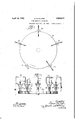
- FIG. 1 is a plan view of a revolving table of a type that be used in conjunction with the forming head or apparatus of-the present invention
- Fig. 2 is an elevational view of the table shown in Fig. 1, with a plurality of stem forming heads of the present invention mounted thereon;
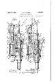
- Fig. 3 is an elevational view of the device; of the present invention showing the forming fingers in lowered or inoperative position, and also showing the glass, tube for'the stem a d he QXh l t tub p iepa ta qry to h g clamp n p sition; I 1 f'.
- Fig. 4 is a view of the forming head? .Qfth present invention similar to showing the formingifingers in elevated er compresshaust
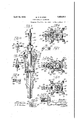
- Fig. 5 is a vertical sectional view taken substantially on the line 5-5 of Fig. l;
- Fig. 6 is a horizontal sectional or plan view taken substantially on the line 6-6 of Fig. 4;
- Fig. 8 is a horizontal sectional view taken substantially on the line 8-8 of Fig. at
- Fig. 11 is a detail view of the spring mounting for the stem tube clamping device
- Fig. 12 is a detail view taken substantially on the line 12-12 of Fig. 11;
- Fig. 13 is a detail viewof the exhaust tube clamp engaging and disengaging mechanism, showing the parts in engaged position;
- Fig. 14 is a view similar to Fig. 13, showing the parts in disengagedor released position; 7 V
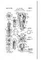
- Fig. 15 is an elevational view, partly in vertical section, showing the wire holding block and glass stem followingthe forming operation;
- Fig. 16 is a transverse sectional view taken substantially on the line 1616 of Fig. 15;
- Fig. 17 is a sectional view taken substantially'on the line 1717 of F ig. 15;
- Fig. 19 is a sectional view taken subctan tially on the line 1919 of 15;
- Fig. 20 is a vertical sectional View of the wire block taken substantially onthe line 202O of Fig. 16 i
- Fig. 21 is a vertical sectional view .taken substantially on the line 21-21 of Fig. 17;
- F ig.. 22 is a detail view of the slidable pressing finger sleeve
- Fig. 23 is an elevational view of a modified form of construction in which the primary or relatively narrow pressing blocks operate slightly in advance of the secondary blocks which approach the stem in a direction perpendicular to that of the primary pressing blocks;
- Fig. 24 is a plan view of the structure shown in Fig. 23;
- Fig. 25 is a vertical'section taken substantially on the line 2525 of Fig. 23;
- Fig. 26 is a detail plan view of the sprin ring interposed between the sliding collars in the form of construction shown in Fig. 23;
- Fig. 27 is a sectional view taken on the line 27-27 of Fig. 26.
- the stem pressing heads of the present invention are shown operatively mounted upon a revolving table 30 which is adapted to support a plurality of heads on the upper surface adjacent the periphery in such manneras to index or carry the heads to successive heating or operative stations in carrying out the process of forming and pressing the stems.
- This operating mechanism is not shown in detail inasmuch as it forms no part of the present invention but illustrates the general method of use.
- Each head generally designated as 31, is rotatably mounted in a socket provided on the table 30.
- the table 30 is revolved in a step by step or intermittent motion and also the individual heads 31 are rotated within the sockets.
- the stem tubes and exhaust tubes may be mounted in the head at loading and unloading station 32.
- a heating fire is applied. to the stem tube during an interval of rest of the revolving table 31, and while the head in this position is rotating.
- a more intense heat is applied at station 34 to gradually raise the temperature of the tube, and at station 35 extremely hot flames are directed upon the tube, at which point the glass has commenced to collapse and is in a molten state, susceptible to pressing and forming.
- the pressing fingers are operated by elevation of the operating rod hereinafter described, and at station 36 the same is subjected to an annealing fire to gradually reduce the temperature after the pressing operation.
- the completed stems are placed in a separate annealing machine for further gradual cooling to avoid cracking.
- the device of the present invention preferably comprises a main cylindrical support 37 having a lower reduced bore to receive a vertically slidable operating rod 38.
- the upper end of rod 38 is pivotally connected to a transverse wrist pin 39 vertically movable in slots 40.
- Wrist pin 39 is connected to and adapted to carry a slidable sleeve member 41 normally adapted to rest in lowered position on a lower collar 42 rigidly secured to the main support 37, and the upper movement of sleeve 41 is limited by an adjustable collar 43 surrounding member 37 and adjustable at different elevations by means of set screws 44:.
- the upper portion of cylinder 37 is adapted to receive a wire holding block 45 positioned in place by means of laterally extending pins 46 which register in corresponding notches on the upper surface of cylinder 37.
- the wire holding block 45 is composed of an upper portion 47 and lower portion 48 secured together by screws 49.
- the upper block portion i7 is preferably provided with mary. supporting wires. The relative length of these wlresis determinedby thebase of ation by the respective arms and pressing a transverse opening 51 in the upper. portion of the member 48.
- the present invention provides for aset of secondary supportingwires 52 and a see- Y and set 53. It willbe understoodfthat'any number-of wires may be employed','but for convenience in illustrationand description, a
- wires 52 and 53 are preferably of considera- Ibly greater length than the wires 50, and are adapted to extend through opening in portion 48 to the'base of slots 54. .After being :embeddedand sealed in the stem by the pressingoperation hereinafter described, the wires 52 and 53 provide auxiliary element supports disposed in-planes perpendicular to theplane of "the primary wires 50, and transversely adjacent theends of the row of wires 50. These wires-may be employed, therefore, to increased advantage in supporting elements,
- each arm-56 is also provided at its upper extremity with a pressing block .58 of a length equivalent to the linear portion of the stem tohe pressed, and of .a width less than that occupied by the wires 50.
- a length of glass tubing .59 is clamped in osition as shown in Figs. 3 and 4, and, as
- Arms 60 an'd '61 are each provided with a pressing block 62 having a substant ally flat Y surface adapted to contact with and press the molten glass 59, and thus, at the completion of a pressing operation, thepress stem assumesthe positionshown in Fig. 9, with the main or primary supporting wires sealed in the central portion, and the laterally disposed auxiliary or secondary supporting Wires 52 pressing relation.
- a lamping and self-centering device for thetube 59 is also provided and comprises;
- an upper mounting member 64 Mounted directly below the upper collar 55 and rigidly connected to the cylinder 37 is an upper mounting member 64 having a laterally oifset portion 65 up on which is mounted vertically ex-z" tending posts 66.
- Clamping fingers67fand 68 are pivotally mounted adjacent the upper portion of post 66 to swing in a horizontal plane, and athree-point contact for engage- V ment with tube 59 is provided by an inward-L- ly extending portion 69on finger 67', and in- .ward projections 70 on finger 68, each of the projections 70'being tapered at the endsin-accordance with the curved surface of the engaged glass, as shown.
- toggle link 71 is a toggle link 71
- a second toggle link 72 is pivotally connected to finger 67
- These toggle links are pivotally connected together and also to the upper extremity of a tube clamp releasing lever 73 pivotally mounted on the supporting-member 64 and provided'with an operating knob 7 4.
- lever 73 extends within vertical slots 75 of a shell 76, secured to the adjacent side of: the cylinder 37, and disposed within shell 76- movable and vertically swingable clamping fingers 79 and 80.
- these fingers are likewise arranged to provide a three-point contact on the exhaust tube 7 8- by means of a block 81 and projection 82 on finger 79, and an inwardly extending projection 83 on finger 80.
- Fingers 7 9 and 80. are pivotally mounted both forlimited horizontal movement toward and away from each other, andfor vertical Pivotally connected.
- .uum tube for example, and is maintainedin clamped position by a pair of horizontally-- movement upon a Vertically extending pin 84: mounted upon the upper extremity of post 85 for horizontal movement, and by pivotal mounting upon transverse pin 86.
- the opposite ends of fingers 79 and 80 are offset and spaced apart for disposition upon either side of a connecting link 87, the upper portion of which is provided with a vertical slot to receive a transverse pin 88 which likewise extends through openings in the adjacent ends of fingers 79 and 80.
- a compression spring 89 is mounted between the end of finger 80 and one end of pin 88, tending normally to urge the ends of fingers 7 9 and 80 together to the position shown in Fig. 14, whereby they are in releasing or disengaged position.
- Connecting link 87 is pivotally mounted upon the upper extremity of an operating bar 91 vertically slidable in brackets 92 and 93 secured to post 85. Bar 91 is normally urged upwardly by compression spring 94 interposed between bracket 93 and stop 95 mounted on the bar 91. In this position the shoulder portion 90 of link 87 is adapted to maintain the adjacent ends of fingers 79 and 80 in spread relation, thus clamping the opposite ends on the exhaust tube 78.
- Bar 91 may be temporarily locked in lowered position by means of a notch 96 adapted to engage the adjacent portion of member 64 upon a slight shifting inwardly of bar 91 by means of knob 97 to the position shown in Fig. 3, and this operation is also assisted by a lower notch 98 adapted to engage bracket 93 when in the position shown in Fig. 3.
- shoulder 90 is disengaged from fingers 7 9 and 80, causin the clamping portions to spread laterally to disengage the exhaust tube 78 through the action of the compression spring 89.
- the clamping fingers are elevated to the position shown in Fig.
- auxiliary wire supports 52 and 53 in acting upon molten glass in a plastic condi-' tion, with these pressing operations applied from diametrically opposite directions and perpendicularly to the planes of the wires, a more substantial and durable seal is obta ined.
- the arms 56 and 57 are connected by links 99 to an upper slidable sleeve 100 which carries transverse pin 101 movable in the vertical slots 40.
- the other pair of arms 60 and 61 are connected by links 102 to a lower slidable sleeve 103.
- Sleeve 103 carries a transverse pin 104 pivotally connected to the upper extremity of operating rod 38.
- a split spring ring 105 Interposed between sleeves 100 and 103 is a split spring ring 105 normally adapted to maintain the sleeves spaced a slight distance to obtain the differential pressing operations described.
- upper sleeve 100 contacts with collar 43 which brings the pressing blocks to the positions shown in Fig. 24. Thereafter'the elevation of rod 38 continues a slight distance until spring 105 is compressed, in the position shown in Fig. 25,'and the pressing blocks are in the final pressing position. It will be understood that when rod 38 is released, the slidable sleeves and the connected links and pressing arms descend by gravity.
- the operation of the mechanism has bee indicated in conjunction with the foregoing description and construction.
- the element supporting wires for sealing within the stem are first disposed in the wire holding block 45, which is then placed in the cylinder 37.
- the glass tube 59 for the stem is then clamped in position manipulating the knob 7 4 and the exhaust tube 7 8 is clamped in position by manipulation of knob 97 attached to the bar 91.
- the head is carried through the desired heating operations for reducing the stem tube 59 to a molten condition suitable for pressing, and in the pressing operation, operating rod 38 is elevated, bringing the pressingarms and pressing blocks into operative position as above described.
- the construction permits of convenient and rapid operation, while at the same time producing improved results in the formation of stems, as described.
- Apparatus of the character described comprising, in combination, means for bold ing a plurality of main element supporting members in substantial alignment and'for holding auixiliary element supporting members in transverse relation to said main supporting members, means for clamping a stem forming tube, and means for pressing said tube to seal said supporting members, said pressing means comprising a pair of pressing members movable in a direction substantially perpendicular to said main supporting members, and a second pair of pressing members movable in a direction substantially perpendicular to said auxiliary supporting members.
- Apparatus of the character described comprising, in combination, a Wire holding L-block constructed and arranged to position bers in a substantially aligned row, said block 7 also arranged to position auxiliary clement supporting members transversely at one end of said row of main supporting members, and 7 means for pressing molten glass to seal said supporting members, said pressing means comprising a pair of compressing blocks movable in converging relation in a direction perpendicular to said roW of main supporting members, and a second pressing block movable in a direction substantially perpendicular to the plane of said auxiliary supporting members.
- Apparatus of the character described comprising, in combination, a Wire holding block constructed and arranged to position a plurality of main element supporting members in a substantially aligned row, said block also arranged'to position auxiliary'element supporting members transversely at one end of said row of main supporting members, and means for pressing molten glass to seal said.
- said pressing means comprising a pair of pressing blocks each of less width than thelength of the row of main supporting members, and also comprising a pressing block of greater Width than the area occupied by said auxiliary supporting menbers.
- Apparatus of the character described comprising, in combination, a holding block arranged to hold a plurality of main support ing Wires in substantially the same plane, said "block also arranged to hold auxiliary supportingwires in a plane transverse to said main supporting Wires, pressing blocks adapted to compress glass in a direction perpendicular to the plane of said main supporting Wires, and a pressing bloclr adapted to com press glass in a direction perpendicular to the plane of said auxiliary supporting Wires.
- Apparatus of the character described comprising, in combination, a holding block arranged to hold a plurality of main supporting Wires in substantially the same plane, said bloclr also arranged to hold auxiliary supporting Wires in a plane transverse to said main supporting wires, pressing blocks adapted to compress glass in a direction perpendicular to the plane of said main supporting I main supporting Wires, a pair of pressing blocks adapted to compress glass in a d1rec-;
- a pressing block adapted to V said block also arranged to hold auxiliary supportingwires inra plane transverse to said main-supporting wires, a pair of pressing c blocks adaptedto compress glass in a dir tion perpendicular to the plane of said main supporting Wires, a pressing block-adapted to compress glass in a direction perpendicular tot e plane of said auxiliary supporting Wires, and clamping means ior supporting a tube in a position for engagement by said:
- Apparatus of the character described comprising, in combination, a holding block arranged to hold a plurality of main supporting Wires in substantially the same plane,
- said block also arranged to hold auxiliary supporting Wires in a plane transverse to said main supporting Wires, pressing blocks adapted to compress glass in a directionpe'rpendicular to the plane of said main" supporting Wires,'a pressing block adapted to compress glass in a direction perpendicular to the plane of said auxiliary supporting Wires, means for operatlng said pressing blocks simultaneously, and clamping means for supporting a tube in a position for engagement by said pressing blocks.
- Apparatus of the character described comprising, in combination, a holding block arranged to hold a plurality of main supporting Wires in substantially the same plane, said block also arranged to hold auxiliary supporting Wires in a plane transverse to said main supporting Wires, a pair of pressing oblocks adapted to compress glass in a direction perpendicular to the plane of said main supporting Wires, a pressing block adapted to compress glass in a direction perpendicular to the plane of said auxiliary supporting 5; Wires, means for operating said pair of compressing blocks slightly in advance of said last mentioned pressing block, and clamping means for supporting a tube in a position for V engagement by said pressing blocks.
- a stem pressing head comprising a supporting member, acollar secured to said supporting member, a block for holding element supports, a clamping member adapted to position a stem tube adjacent said block With a portion surrounding said element supports,
- a pair of pressing members pivotally mounted upon said collar and provided With main pressing blocks
- a second pair of pressing members pivotally mounted upon said collar and provided with auxiliary pressing blocks arranged to laterally overlie said main pressing blocks, and means for simultaneously moving said pressing members into operative position to engage said stem tube.
- stem pressing head comprising a sup porting member, a collar secured to said supporting member, a block for holding element supports, a clamping member adapted to position a stem tube adjacent said block with :21 portion surrounding said element supports,
- a pair of pressing members pivotally mounted upon said collar and provided With main pressing blocks
- a second pair of pressing members pivotally mounted upon said collar and provided With auxiliary pressing blocks arranged to laterally overlie said main pressing blocks
- a sleeve member slidably mounted upon said supporting member, link members connecting said sleeve member and .said pressing members, and means for open ating said sleeve member to simultaneously .move said pressing members into operative position to engage said stem tube.
- a stem pressing head comprising a isupporting member, a collar secured to said supporting member, a block for holding element supports, a clamping member adapted to position a stem tube adjacent said block with a portion surrounding said element supports, a pair of pressing members pivotally mounted upon said collar and provided With main pressing blocks, a second pair of pressing members pivotally mounted upon said collar and provided with auxiliary pressing Ci blocks arranged to laterally overlie said main GEORGE D. MCOABE.
Landscapes
- Engineering & Computer Science (AREA)
- Manufacturing & Machinery (AREA)
- Joining Of Glass To Other Materials (AREA)
Description
A ril 12, 1932. G D MCCABE 1,853,911
I I STEM PRESSING APPARATUS Original Filed Oct. 51, 1930 4 Sheets-Sheet l mam W April 32- G. D. MCCABE 1,853,911
STEM PRESSING A PARATUs Original Filed Oct. 31, 1930 4 Sheets-Sheet 3 A ril 12, 1932. G, D'M ABE 1,853,911
STEM PRES SING APPARATUS Original Filed 0 011. 31, 1930 4 Sheets-Sheet 4 I JE- gg I 52' i 1 1 11111715111); F /9 Z .2 fl- Patented Apr. '12, 1932 UNITED stares PATENT onion.
e ema e an. on enxcaeo, I N S smnn ennssme APPARATUS Application filed October 31, 1330, Serial No. 492,446. Renewed. February 15, 193 2.
This invention relates to stem pressing apparatus, and more particularly apparatus or mechanism for pressing-and sealing the element supper-ting stem of tubes, such as vacu 5 um tubes, gas enclosed tubes, and the like. A
action between the compressed or molded:
' glass or equivalent material forming the stem, and the element support ng members or wires. An additional object is the prov-il sion of stem forming mechanism constructed and arranged to produce, element, support ng stems having the supporting members or wires disposed in a relationship whereby increased support for the elements is afi'orded, and bending or distortion of the supports prevented. An additional object resides in the provision ofimp'roved stem forming mechanism whe reby the glass compressing members actin a direction perpendicular to the planes in which the element-Y supporting members are disposed for the pur'pes'efof avoiding a sliding action in the molten glass. The result of thisconstructionandarrangement is to efiect a tighter seal or cohesion between the compressed glass and the embedded element supporting members or wires, and to prevent leakage, as well as .topreventinternal strains inthe glass. H I
' The apparatus of the present invention is further object is .the provi'sion or im proved stem clamping mechanism, as well as the provision of improved exhaust tube clamping mechanism. In radio. tube construction, for example, the element supporte ing members, such as the wires which supespecially designed for theformation eleposidtion,v and the stem tube and ex .tuhe c1a p=i gmem ersin engag d nos-men;
port the plate and grid elements, are positioned substantially in alignment or in the same plane. These supporting wires are'con structed of soft metal such as nickel wire, and 1 any sudden j arringhas a tendency to cause a" bending at the pointfof juncture'Wit-h the stem. This presents a difliculty in connection with transporting and handling tubes 7 before they are actuallyput to use, inasmuch as any. slight bending or distortion will set up microphonics and directly impair-the effici-ency'of the tube. An additional object of the. present invention, therefore, isthe provision of a stem forming head designed to form a supporting stem which thep r'i mary supporting wires are supplemented by secondary wires disposed laterally with'respect to the primary wires whereby, upon placing a connection between the two, bending or distortion of the primary supporting 'wires is prevented by the later 211 supports afforded by thesecondary wires. 5
Other objects will appear hereinafter.
The invention consists in the combinations and arrangements ofparts hereinafter described and claimed.
The invention will be best understood by which 2 Fig. 1 is a plan view of a revolving table of a type that be used in conjunction with the forming head or apparatus of-the present invention i i Fig. 2 is an elevational view of the table shown in Fig. 1, with a plurality of stem forming heads of the present invention mounted thereon;
Fig. 3 is an elevational view of the device; of the present invention showing the forming fingers in lowered or inoperative position, and also showing the glass, tube for'the stem a d he QXh l t tub p iepa ta qry to h g clamp n p sition; I 1 f'.
Fig. 4 is a view of the forming head? .Qfth present invention similar to showing the formingifingers in elevated er compresshaust Fig. 5 is a vertical sectional view taken substantially on the line 5-5 of Fig. l;
Fig. 6 is a horizontal sectional or plan view taken substantially on the line 6-6 of Fig. 4;
Fig. 7 is a detail view taken substantially on the line 77 of Fig. l;
Fig. 8 is a horizontal sectional view taken substantially on the line 8-8 of Fig. at
Fig. 9 is a horizontal sectional view taken substantially on the line 9-9 of i;
Fig. 10 is a detail section taken substantially on the line 1010 of Fig. 4;
Fig. 11 is a detail view of the spring mounting for the stem tube clamping device;
Fig. 12 is a detail view taken substantially on the line 12-12 of Fig. 11;
Fig. 13 is a detail viewof the exhaust tube clamp engaging and disengaging mechanism, showing the parts in engaged position;
Fig. 14: is a view similar to Fig. 13, showing the parts in disengagedor released position; 7 V
Fig. 15 is an elevational view, partly in vertical section, showing the wire holding block and glass stem followingthe forming operation;
Fig. 16 is a transverse sectional view taken substantially on the line 1616 of Fig. 15;
Fig. 17 is a sectional view taken substantially'on the line 1717 of F ig. 15;
Fig. 18 is a sectional view taken substantially on the line 1818 of Fig. 15;
Fig. 19 is a sectional view taken subctan tially on the line 1919 of 15;
Fig. 20 is a vertical sectional View of the wire block taken substantially onthe line 202O of Fig. 16 i Fig. 21 is a vertical sectional view .taken substantially on the line 21-21 of Fig. 17;
F ig.. 22 is a detail view of the slidable pressing finger sleeve;
Fig. 23 is an elevational view of a modified form of construction in which the primary or relatively narrow pressing blocks operate slightly in advance of the secondary blocks which approach the stem in a direction perpendicular to that of the primary pressing blocks;
Fig. 24 is a plan view of the structure shown in Fig. 23;
Fig. 25 is a vertical'section taken substantially on the line 2525 of Fig. 23;
Fig. 26 is a detail plan view of the sprin ring interposed between the sliding collars in the form of construction shown in Fig. 23; and
Fig. 27 is a sectional view taken on the line 27-27 of Fig. 26.
As shown in Figs. 1 and2, the stem pressing heads of the present invention are shown operatively mounted upon a revolving table 30 which is adapted to support a plurality of heads on the upper surface adjacent the periphery in such manneras to index or carry the heads to successive heating or operative stations in carrying out the process of forming and pressing the stems. This operating mechanism is not shown in detail inasmuch as it forms no part of the present invention but illustrates the general method of use. Each head generally designated as 31, is rotatably mounted in a socket provided on the table 30. By suitable driving mechanism, the table 30 is revolved in a step by step or intermittent motion and also the individual heads 31 are rotated within the sockets. In the typical installation illustrated, the stem tubes and exhaust tubes, as well as the wire holding block, may be mounted in the head at loading and unloading station 32. At station 33 a heating fire is applied. to the stem tube during an interval of rest of the revolving table 31, and while the head in this position is rotating. A more intense heat is applied at station 34 to gradually raise the temperature of the tube, and at station 35 extremely hot flames are directed upon the tube, at which point the glass has commenced to collapse and is in a molten state, susceptible to pressing and forming. Also, at this station, the pressing fingers are operated by elevation of the operating rod hereinafter described, and at station 36 the same is subjected to an annealing fire to gradually reduce the temperature after the pressing operation. Upon removal from the machine, the completed stems are placed in a separate annealing machine for further gradual cooling to avoid cracking.
The device of the present invention preferably comprises a main cylindrical support 37 having a lower reduced bore to receive a vertically slidable operating rod 38. The upper end of rod 38 is pivotally connected to a transverse wrist pin 39 vertically movable in slots 40. Wrist pin 39 is connected to and adapted to carry a slidable sleeve member 41 normally adapted to rest in lowered position on a lower collar 42 rigidly secured to the main support 37, and the upper movement of sleeve 41 is limited by an adjustable collar 43 surrounding member 37 and adjustable at different elevations by means of set screws 44:. The upper portion of cylinder 37 is adapted to receive a wire holding block 45 positioned in place by means of laterally extending pins 46 which register in corresponding notches on the upper surface of cylinder 37. As a convenience in manufacture, the wire holding block 45 is composed of an upper portion 47 and lower portion 48 secured together by screws 49. The upper block portion i7 is preferably provided with mary. supporting wires. The relative length of these wlresis determinedby thebase of ation by the respective arms and pressing a transverse opening 51 in the upper. portion of the member 48. In addition to the wires 50, the present invention provides for aset of secondary supportingwires 52 and a see- Y and set 53. It willbe understoodfthat'any number-of wires may be employed','but for convenience in illustrationand description, a
pair of wires for each set is indicated. The
. wires 52 and 53 are preferably of considera- Ibly greater length than the wires 50, and are adapted to extend through opening in portion 48 to the'base of slots 54. .After being :embeddedand sealed in the stem by the pressingoperation hereinafter described, the wires 52 and 53 provide auxiliary element supports disposed in-planes perpendicular to theplane of "the primary wires 50, and transversely adjacent theends of the row of wires 50. These wires-may be employed, therefore, to increased advantage in supporting elements,
. both in line or plane of support and in positions laterally thereof toafl'ord a more stable and .efi'ective eleme'nt support, and to resist .andprevent displacement of the parts as above referred to.
' Rigidly mounted adjacent the upper por: tion of cylindrical support 37 is a collar 55 upon which are pivotally mounted the lower ends of diametrically opposed presslng arms 56 and 57. 'These'arms are formed with a pronounced curvature whereby when brought into pressing position with the glass stem,
' the approach will be substantially in a horizontal direction, and each arm-56 is also provided at its upper extremity with a pressing block .58 of a length equivalent to the linear portion of the stem tohe pressed, and of .a width less than that occupied by the wires 50.
A length of glass tubing .59 is clamped in osition as shown in Figs. 3 and 4, and, as
' ereinafter described, directly abo-vethe wire holding block 45, and in position to enclose the upwardly projecting wires in the sealed portion. Thus, when arms 56 and 57 converge .in fa direction perpendicular to the plane of the ,main wires 50, the glass stem *is pressed as shown .in Fig. 9,, .forclng the molten glass around the .wires and providing a tight seal. Simultaneously with this pressing "operation, a second pair o-f-arms-60 and -61, correspondingly pivotedto the-collar 55,
- is forced inwardlyinopposed relation and in directions perpendicular to the direction of movement of arms 56 and 57 and heads 58. Arms 60 an'd '61 are each provided with a pressing block 62 having a substant ally flat Y surface adapted to contact with and press the molten glass 59, and thus, at the completion of a pressing operation, thepress stem assumesthe positionshown in Fig. 9, with the main or primary supporting wires sealed in the central portion, and the laterally disposed auxiliary or secondary supporting Wires 52 pressing relation.
and 53 sealed within transverse end portions.
This substantial simultaneous pressing operblocks is performed through a plurality of "links 63, each having its upward end pivotal-ily connected to one of the pressing arms at a point intermediate the-ends thereof, and having the lower end pivoted to the slidab-le sleeve 41. By this construction and arrangement,
when the actuating rod 38'is elevated, the;
pressing arms and blocks mounted thereon are simultaneously brought into converging A lamping and self-centering device for thetube 59 is also provided and comprises;
the following mechanism. Mounted directly below the upper collar 55 and rigidly connected to the cylinder 37 is an upper mounting member 64 having a laterally oifset portion 65 up on which is mounted vertically ex-z" tending posts 66. Clamping fingers67fand 68 are pivotally mounted adjacent the upper portion of post 66 to swing in a horizontal plane, and athree-point contact for engage- V ment with tube 59 is provided by an inward-L- ly extending portion 69on finger 67', and in- .ward projections 70 on finger 68, each of the projections 70'being tapered at the endsin-accordance with the curved surface of the engaged glass, as shown. to Ifinger 68 is a toggle link 71, and a second toggle link 72 is pivotally connected to finger 67 These toggle links are pivotally connected together and also to the upper extremity ofa tube clamp releasing lever 73 pivotally mounted on the supporting-member 64 and provided'with an operating knob 7 4. At the lower extremity, below the pivotal mounting, lever 73 extends within vertical slots 75 of a shell 76, secured to the adjacent side of: the cylinder 37, and disposed within shell 76- movable and vertically swingable clamping fingers 79 and 80. By reference to Fig. 6, it will be noted that these fingers are likewise arranged to provide a three-point contact on the exhaust tube 7 8- by means of a block 81 and projection 82 on finger 79, and an inwardly extending projection 83 on finger 80. Fingers 7 9 and 80. are pivotally mounted both forlimited horizontal movement toward and away from each other, andfor vertical Pivotally connected.
.uum tube, for example, and is maintainedin clamped position by a pair of horizontally-- movement upon a Vertically extending pin 84: mounted upon the upper extremity of post 85 for horizontal movement, and by pivotal mounting upon transverse pin 86. The opposite ends of fingers 79 and 80 are offset and spaced apart for disposition upon either side of a connecting link 87, the upper portion of which is provided with a vertical slot to receive a transverse pin 88 which likewise extends through openings in the adjacent ends of fingers 79 and 80. A compression spring 89 is mounted between the end of finger 80 and one end of pin 88, tending normally to urge the ends of fingers 7 9 and 80 together to the position shown in Fig. 14, whereby they are in releasing or disengaged position.
Engagement or clamping relation of the fingers is effected by a shoulder portion 90 on the connecting link 87 which tends to spread the adjacent ends of fingers 79 and 80, and consequently force the opposite clamping ends into clamping position. Connecting link 87 is pivotally mounted upon the upper extremity of an operating bar 91 vertically slidable in brackets 92 and 93 secured to post 85. Bar 91 is normally urged upwardly by compression spring 94 interposed between bracket 93 and stop 95 mounted on the bar 91. In this position the shoulder portion 90 of link 87 is adapted to maintain the adjacent ends of fingers 79 and 80 in spread relation, thus clamping the opposite ends on the exhaust tube 78. Bar 91 may be temporarily locked in lowered position by means of a notch 96 adapted to engage the adjacent portion of member 64 upon a slight shifting inwardly of bar 91 by means of knob 97 to the position shown in Fig. 3, and this operation is also assisted by a lower notch 98 adapted to engage bracket 93 when in the position shown in Fig. 3. During the initial movement of bar 91 in a downward direction, shoulder 90 is disengaged from fingers 7 9 and 80, causin the clamping portions to spread laterally to disengage the exhaust tube 78 through the action of the compression spring 89. As the bar 91 continues in lowering movement, the clamping fingers are elevated to the position shown in Fig. 3 by pivotal movement upon the transverse pin 88, and 1t Wlll also be understood that in the reverse clamping movement, the fingers are initially lowered to the proper level as shown in Fig. 4, and finally clamped from opposed horizontal directions by means of the engagement of the shoulder portion 90. It will be noted that the entire clamping mechanism for both the stem tube and the exhaust tube is arranged in alignment and mounted at one side A modified structure and operation in connection with the pressing arms is shown in Figs. 23 to 27. By this construction the relatively narrow pressing blocks 58, mounted. upon pressing arms 56 and 57, are intended to" be brought into pressing relation slightly in advance of the fiat surfaced pressing blocks 62, following which blocks 62 continue their pressing movement to the final pressing posi-,
auxiliary wire supports 52 and 53, and in acting upon molten glass in a plastic condi-' tion, with these pressing operations applied from diametrically opposite directions and perpendicularly to the planes of the wires, a more substantial and durable seal is obta ined. In this slightly modified form, the arms 56 and 57 are connected by links 99 to an upper slidable sleeve 100 which carries transverse pin 101 movable in the vertical slots 40. The other pair of arms 60 and 61 are connected by links 102 to a lower slidable sleeve 103. Sleeve 103 carries a transverse pin 104 pivotally connected to the upper extremity of operating rod 38. Interposed between sleeves 100 and 103 is a split spring ring 105 normally adapted to maintain the sleeves spaced a slight distance to obtain the differential pressing operations described. Upon elevation of operating rod 38, upper sleeve 100 contacts with collar 43 which brings the pressing blocks to the positions shown in Fig. 24. Thereafter'the elevation of rod 38 continues a slight distance until spring 105 is compressed, in the position shown in Fig. 25,'and the pressing blocks are in the final pressing position. It will be understood that when rod 38 is released, the slidable sleeves and the connected links and pressing arms descend by gravity.
The operation of the mechanism has bee indicated in conjunction with the foregoing description and construction. The element supporting wires for sealing within the stem are first disposed in the wire holding block 45, which is then placed in the cylinder 37. The glass tube 59 for the stem is then clamped in position manipulating the knob 7 4 and the exhaust tube 7 8 is clamped in position by manipulation of knob 97 attached to the bar 91. Thereafter the head is carried through the desired heating operations for reducing the stem tube 59 to a molten condition suitable for pressing, and in the pressing operation, operating rod 38 is elevated, bringing the pressingarms and pressing blocks into operative position as above described. The construction permits of convenient and rapid operation, while at the same time producing improved results in the formation of stems, as described.
While I have illustrated and described the a a plurality of main element supporting mempreferred former construction for carrying my. invention into elfect, this-is capable of variation and modification Without departing from the spirit of the invention. 1, therefore, do not Wish to be limited to the precise details of c onstruction'set forth, but desire to,
avail myself of such-variations and modifications as come Within the scope of the appended claims. I 7
Having thus described my invention, What I claim as new and desire to secure by Letters Patent is: V V
1. Apparatus of the character described comprising, in combination, means for bold ing a plurality of main element supporting members in substantial alignment and'for holding auixiliary element supporting members in transverse relation to said main supporting members, means for clamping a stem forming tube, and means for pressing said tube to seal said supporting members, said pressing means comprising a pair of pressing members movable in a direction substantially perpendicular to said main supporting members, and a second pair of pressing members movable in a direction substantially perpendicular to said auxiliary supporting members. 7
2. Apparatus of the character described comprising, in combination, a Wire holding L-block constructed and arranged to position bers in a substantially aligned row, said block 7 also arranged to position auxiliary clement supporting members transversely at one end of said row of main supporting members, and 7 means for pressing molten glass to seal said supporting members, said pressing means comprising a pair of compressing blocks movable in converging relation in a direction perpendicular to said roW of main supporting members, and a second pressing block movable in a direction substantially perpendicular to the plane of said auxiliary supporting members.
3. Apparatus of the character described comprising, in combination, a Wire holding block constructed and arranged to position a plurality of main element supporting members in a substantially aligned row, said block also arranged'to position auxiliary'element supporting members transversely at one end of said row of main supporting members, and means for pressing molten glass to seal said. supporting members said pressing means comprising a pair of pressing blocks each of less width than thelength of the row of main supporting members, and also comprising a pressing block of greater Width than the area occupied by said auxiliary supporting menbers. V
4. Apparatus of the character described comprising, in combination, a holding block arranged to hold a plurality of main support ing Wires in substantially the same plane, said "block also arranged to hold auxiliary supportingwires in a plane transverse to said main supporting Wires, pressing blocks adapted to compress glass in a direction perpendicular to the plane of said main supporting Wires, and a pressing bloclr adapted to com press glass in a direction perpendicular to the plane of said auxiliary supporting Wires.
5. Apparatus of the character described comprising, in combination, a holding block arranged to hold a plurality of main supporting Wires in substantially the same plane, said bloclr also arranged to hold auxiliary supporting Wires in a plane transverse to said main supporting wires, pressing blocks adapted to compress glass in a direction perpendicular to the plane of said main supporting I main supporting Wires, a pair of pressing blocks adapted to compress glass in a d1rec-;
tion perpendicular to the plane of said main compress glass in a directionperpendicular to theplane of said auxiliary supporting, Wires, and means for operating said pair of pressing blocks slightly in advance of said last mentioned pressing block.
7.Apparatus of the character described comprising, in combination, a holding block arranged to hold a plurality of main support; .1
ing wires in substantially the same plane,
.95? supporting Wires, a pressing block adapted to V said block also arranged to hold auxiliary supportingwires inra plane transverse to said main-supporting wires, a pair of pressing c blocks adaptedto compress glass in a dir tion perpendicular to the plane of said main supporting Wires, a pressing block-adapted to compress glass in a direction perpendicular tot e plane of said auxiliary supporting Wires, and clamping means ior supporting a tube in a position for engagement by said:
pressing blocks. v
'8. Apparatus of the character described comprising, in combination, a holding block arranged to hold a plurality of main supporting Wires in substantially the same plane,
said blockalso arranged to hold auxiliary supporting Wires in a plane transverse to said main supporting Wires, pressing blocks adapted to compress glass in a directionpe'rpendicular to the plane of said main" supporting Wires,'a pressing block adapted to compress glass in a direction perpendicular to the plane of said auxiliary supporting Wires, means for operatlng said pressing blocks simultaneously, and clamping means for supporting a tube in a position for engagement by said pressing blocks.
9. Apparatus of the character described comprising, in combination, a holding block arranged to hold a plurality of main supporting Wires in substantially the same plane, said block also arranged to hold auxiliary supporting Wires in a plane transverse to said main supporting Wires, a pair of pressing oblocks adapted to compress glass in a direction perpendicular to the plane of said main supporting Wires, a pressing block adapted to compress glass in a direction perpendicular to the plane of said auxiliary supporting 5; Wires, means for operating said pair of compressing blocks slightly in advance of said last mentioned pressing block, and clamping means for supporting a tube in a position for V engagement by said pressing blocks.
10. A stem pressing head comprising a supporting member, acollar secured to said supporting member, a block for holding element supports, a clamping member adapted to position a stem tube adjacent said block With a portion surrounding said element supports,
a pair of pressing members pivotally mounted upon said collar and provided With main pressing blocks, a second pair of pressing members pivotally mounted upon said collar and provided with auxiliary pressing blocks arranged to laterally overlie said main pressing blocks, and means for simultaneously moving said pressing members into operative position to engage said stem tube.
11.1%.. stem pressing head comprising a sup porting member, a collar secured to said supporting member, a block for holding element supports, a clamping member adapted to position a stem tube adjacent said block with :21 portion surrounding said element supports,
a pair of pressing members pivotally mounted upon said collar and provided With main pressing blocks, a second pair of pressing members pivotally mounted upon said collar and provided With auxiliary pressing blocks arranged to laterally overlie said main pressing blocks, a sleeve member slidably mounted upon said supporting member, link members connecting said sleeve member and .said pressing members, and means for open ating said sleeve member to simultaneously .move said pressing members into operative position to engage said stem tube.
12. A stem pressing head comprising a isupporting member, a collar secured to said supporting member, a block for holding element supports, a clamping member adapted to position a stem tube adjacent said block with a portion surrounding said element supports, a pair of pressing members pivotally mounted upon said collar and provided With main pressing blocks, a second pair of pressing members pivotally mounted upon said collar and provided with auxiliary pressing Ci blocks arranged to laterally overlie said main GEORGE D. MCOABE.
Priority Applications (1)
| Application Number | Priority Date | Filing Date | Title |
|---|---|---|---|
| US492446A US1853911A (en) | 1930-10-31 | 1930-10-31 | Stem pressing apparatus |
Applications Claiming Priority (1)
| Application Number | Priority Date | Filing Date | Title |
|---|---|---|---|
| US492446A US1853911A (en) | 1930-10-31 | 1930-10-31 | Stem pressing apparatus |
Publications (1)
| Publication Number | Publication Date |
|---|---|
| US1853911A true US1853911A (en) | 1932-04-12 |
Family
ID=23956285
Family Applications (1)
| Application Number | Title | Priority Date | Filing Date |
|---|---|---|---|
| US492446A Expired - Lifetime US1853911A (en) | 1930-10-31 | 1930-10-31 | Stem pressing apparatus |
Country Status (1)
| Country | Link |
|---|---|
| US (1) | US1853911A (en) |
Cited By (3)
| Publication number | Priority date | Publication date | Assignee | Title |
|---|---|---|---|---|
| US2836011A (en) * | 1956-02-03 | 1958-05-27 | Sylvania Electric Prod | Glass envelope forming and sealing apparatus |
| US2857711A (en) * | 1955-01-31 | 1958-10-28 | Rca Corp | Apparatus for making electron device stems |
| US3167045A (en) * | 1961-05-17 | 1965-01-26 | Pure Carbon Company Inc | Refractory fixture |
-
1930
- 1930-10-31 US US492446A patent/US1853911A/en not_active Expired - Lifetime
Cited By (3)
| Publication number | Priority date | Publication date | Assignee | Title |
|---|---|---|---|---|
| US2857711A (en) * | 1955-01-31 | 1958-10-28 | Rca Corp | Apparatus for making electron device stems |
| US2836011A (en) * | 1956-02-03 | 1958-05-27 | Sylvania Electric Prod | Glass envelope forming and sealing apparatus |
| US3167045A (en) * | 1961-05-17 | 1965-01-26 | Pure Carbon Company Inc | Refractory fixture |
Similar Documents
| Publication | Publication Date | Title |
|---|---|---|
| US1853911A (en) | Stem pressing apparatus | |
| US2361517A (en) | Sealing apparatus | |
| US2069086A (en) | Transferring mechanism | |
| US2494872A (en) | Method and apparatus for bending tubular glass articles | |
| US2195483A (en) | Stem machine | |
| US2511914A (en) | Method of and apparatus for fabri | |
| US3113010A (en) | Method and apparatus for forming tubular electric lamps and similar devices | |
| US1907533A (en) | Method of and apparatus for mounting filamenis | |
| US2153370A (en) | Apparatus for sealing electric lamps and similar articles | |
| US2565126A (en) | Cathode mount making apparatus | |
| US2414372A (en) | Machine for assembling upholstery springs | |
| US1640442A (en) | Stem-making machine | |
| US1801108A (en) | Filament support making and inserting machines | |
| US2121627A (en) | Apparatus for sealing metal to glass | |
| US1710428A (en) | Method and machine for manufacturing incandescent lamps and similar articles | |
| US2476658A (en) | Glass tube bending apparatus | |
| US1731763A (en) | Means for re-forming coil springs | |
| US2295034A (en) | Tipping-off apparatus | |
| CN105895476A (en) | Energy-saving lamp production device | |
| US2087798A (en) | Hat forming machine | |
| US1730926A (en) | Machine for making vacuum tubes | |
| US1936426A (en) | Sealing-off and dumping mechanism for exhaust machines | |
| US2010097A (en) | Pressing apparatus | |
| US1997219A (en) | Turret press | |
| US1547393A (en) | Universal stem head |