US1853907A - Grinding machine - Google Patents
Grinding machine Download PDFInfo
- Publication number
- US1853907A US1853907A US269919A US26991928A US1853907A US 1853907 A US1853907 A US 1853907A US 269919 A US269919 A US 269919A US 26991928 A US26991928 A US 26991928A US 1853907 A US1853907 A US 1853907A
- Authority
- US
- United States
- Prior art keywords
- shaft
- slide
- secured
- frame
- motor
- Prior art date
- Legal status (The legal status is an assumption and is not a legal conclusion. Google has not performed a legal analysis and makes no representation as to the accuracy of the status listed.)
- Expired - Lifetime
Links
- 239000004020 conductor Substances 0.000 description 3
- MXBCYQUALCBQIJ-RYVPXURESA-N (8s,9s,10r,13s,14s,17r)-13-ethyl-17-ethynyl-11-methylidene-1,2,3,6,7,8,9,10,12,14,15,16-dodecahydrocyclopenta[a]phenanthren-17-ol;(8r,9s,13s,14s,17r)-17-ethynyl-13-methyl-7,8,9,11,12,14,15,16-octahydro-6h-cyclopenta[a]phenanthrene-3,17-diol Chemical compound OC1=CC=C2[C@H]3CC[C@](C)([C@](CC4)(O)C#C)[C@@H]4[C@@H]3CCC2=C1.C1CC[C@@H]2[C@H]3C(=C)C[C@](CC)([C@](CC4)(O)C#C)[C@@H]4[C@@H]3CCC2=C1 MXBCYQUALCBQIJ-RYVPXURESA-N 0.000 description 1
- 238000002485 combustion reaction Methods 0.000 description 1
- 230000000630 rising effect Effects 0.000 description 1
Images

Classifications
-
- B—PERFORMING OPERATIONS; TRANSPORTING
- B24—GRINDING; POLISHING
- B24B—MACHINES, DEVICES, OR PROCESSES FOR GRINDING OR POLISHING; DRESSING OR CONDITIONING OF ABRADING SURFACES; FEEDING OF GRINDING, POLISHING, OR LAPPING AGENTS
- B24B15/00—Machines or devices designed for grinding seat surfaces; Accessories therefor
- B24B15/04—Machines or devices designed for grinding seat surfaces; Accessories therefor on valve members
Definitions
- This invention relates toa grinding machine andparticularly to a ⁇ grindingmachine such as used to grind valves Vof internal combustion engines and similar small articles vor It is an object of this invention tov provide al simple smalll and compact machine. for grinding Valves which can' be readily adjusted for operation, and which is preferably moter driven.
- Fig 2 is al view infront elevation", certain 'parts being broken away and other parts being” shown ⁇ inV vertical section g Figi 3 is a vertical section Vtaken on line '3 ⁇ -3-0,f Figs2; Y .Y 4 is a horizontal section on line 4-4 -ofFig ⁇ .3;andN Y f Fig. 5 is a horizontal section taken on line 5.-'-5 of Fig. 3 shown on ⁇ an enlargedscale, lsaid sections being taken as indicated bythe arrows. fi j l 50 Referring to thedrawingsya machinelis showncomp'rising the jframe J10 of hollow MACHINE 192s! serial No. 269,919.
- PATENT ioFFIcEig boxlike form havingl a surrounding bottom p ange 10a provided with spaced supporting lugs 1105.
- the fframe 10 ' is'provided at one side ywith jthe dove-tailed ribs lOcforming the guidewayffor a .slide 11 fitting on said guideway and extending transversely" ⁇ of the machine.v
- the slide 11 has secured thereto a plate 12 having a-projecting boss 12a vin whichis journaled a screw 13, said screw being held from movement by the collar 14 pinned to said screw at one end of said bearing Vand by the operating handV wheel ⁇ 1 ⁇ 5 disposed at thevother end ofsaidbearing and vheld in place by the nuts 16 threaded on the end of screw.
- the slide 11 has secured th'eretoby ⁇ bolts 17 ⁇ asaddle member 18 lin'which is mounted a'motor19.
- the motor -19 has secured'to one end of its armature or driving shaft 20 Y a grinding wheel 217 the sam-e being heldin place on an arbor 22 secured to said shaft by the' plate 23 vand clamping nuts'24.
- the said driving shaft20 has secured to its end a grooveddriving pulley 25 over which runs a belt ⁇ 26 alsolrunning over and driving a pulley ⁇ 527' keyed tof'one end of a splined shaft .28, thehubof said pulley being journaled I 4in ⁇ a depending portionpllavoflthe slide 11.
- the shaft 28 extendslthrough an aperture in the'cnd of framel() andis :jo'urn'aled at its A'other endin ⁇ one hub of a bearing 29 carried .Y V"on rand forming a vbearing forv ⁇ avertica'l 'shaft 3 0 extending upward ⁇ adjacent onev end of the frame 10.
- Gears 31and32 are respec-Y tively secured to lshafts 28an d 30, said gears meshing Vwith each other and forming the Y driving means Yfor shaft 30.
- the shaft '30 rhas secured thereto immediately'above bear# ing'29 an eccentric SS'disposed' in a slot 10g 1in Vframe 10 and extending transverselyfof the slide 34.
- the slide 34 is movablelength- 107i vformedon 'said frame.
- AThe slide 34 has anupstanding cylindrical portion' 84?) sub,-
- the head 35 has spaced bearing portions 35a in which is journaled a hollow shaft 36.
- a cover 37 extends over and between the portions 37a being secured at its sides to the head 35 by the screws 38.
- the shaft 36 is tapered interiorly and exe teriorly at its end 36a and is threaded at its other end to receive asleeve 39.
- Knurled ornamental cap members are secured at the ends of bearing portions 35a ⁇
- the shaft k36 is interiorly threaded at the end opposite end 36a to receive the threaded hub 41m-of a knurled Wheel 41 having a bore therethrough with a flared inner end.
- a clamping sleeve 42 is carried in shaft 36 having split tapered ends, said sleeve 42 forming .a holding means for the article to be ground, such as the stein 43al of a valve'43.
- the flared end of the bore in hub 41a engages the tapered vend of member 42 .and as member 41 is turned to move hub 41a inwardly, member 42 will be pushed against the tapered end 36a and vcontracted, and will also have its other .end contracted by the flared surface on member 41.
- the stem 4366 is thus firmly clamped Vat separated points and thus held accurately in axial posit-ion in shaft 36.
- the shaft 36 has secured thereto a gear 44 in any suitable manner as, by the set screw 45, which .gear meshes .with a pinion 46 secured to the top of the shaft 30.
- the slide 11 is provided with .a socket 47 adapted to receive the Vdetachable plug 48 to which are connected the conductors l49 for supplying current to. motor 19.
- Conductors -49 will be provided at their other ends with a plug which'can be inserted in any .convenient electric socket.
- the socket 47 will be connected by suitable conductors to a switch 50 ⁇ car ried in the frame and having a projecting operating handle 50a which will be disposed in convenient position 'for operation.
- the valve will also be rotated by shaft 36 being rotated by the ,gear 4-6.
- the valve is thus turned and .simultaneously reciprocatedand the same will be properly and accurately .chineis quite small and is thus very convenient for small establishments such as garages, forl valve grinding purposes.”
- the base is approximately one foot long.
- rlhe machine has sufiicient weight so that it may simply rest on any suitable support and be operated without being secured thereto.
- the machine can be connected for loperation to any convenient lamp socket and 4nobelts are thus necessary.
- the Vparts are comparatively few, compactly arranged, and ⁇ so disposed that there are no moving parts in t-he way of the operator or in which the operator may be caught.
- the device has been amply demonstrated in actual practice and. found to bevery successful and eflicient.
- vapplicants invention which, generally stated, consist-s in a device capable of carrying out the objects above set forth, in the novel parts and combinations of parts disclosed and defined in the appended claims.
- a grinding machine having in combination, a frame, a slide movable transversely thereof, a motor. mounted on said slide, a grinding wheel secured to the rdriving shaft ofsaid motor and rotated thereby, a splined shaft extending longitudinally of said frame below said slide, a slide on said frame rreciprocable toward and from said grinding wheel parallel to the axis thereof, a head rotatable on said slide,.ja member journaled in said head adapted to hold an article to-be ground,I a gear secured to said member, a gear meshing with said gear, a shaft secured to said last mentioned gear and extending vertically through said head and slide, means on said shaft for reciprocating said last inentioned slide, a gear secured to said last men tioned shaft, a gear meshing'with said last mentioned gear and secured to said splined shaft, a pulley carried on said first mentioned slide through which said splined shaft projects, said pulley
- a valve grinding machine having .in
- a valve grinding machine having in combination, a frame, a slide adjustable transversely ofsaid frame, a motor carried on said slide, a grinding wheel attached to the shaft of said motor, a work-carrying slide, slidable longitudinally of said frame in a line Y parallel to the axis of said motor shaft, a
Landscapes
- Engineering & Computer Science (AREA)
- Mechanical Engineering (AREA)
- Finish Polishing, Edge Sharpening, And Grinding By Specific Grinding Devices (AREA)
Description
G. F. KRlE-SEL GRINDING MACHINE April 12, 1932.
Filed April 14, 1928 2 sheets-shear.
wmf/M@ April 12, 1932-- G. F. KRlEsEL 1,853,907
v A GRINDING MACHINE Filed Apri'l 14, 1928 2 Sheets-Sheet 2 44 y Ff 45% Gua wwf FAW/55a,
Patented Apr. 12, 1932 UNITED STATES Gus'rAvE F. KRIESEL, 0F IvIINNiiAroIJIs,y MINNESOTA GRINDING f Application iiled .A] ri1*14,V
This invention relates toa grinding machine andparticularly to a` grindingmachine such as used to grind valves Vof internal combustion engines and similar small articles vor It is an object of this invention tov provide al simple smalll and compact machine. for grinding Valves which can' be readily adjusted for operation, and which is preferably moter driven.
It is a further object lof the inventionv to provide a small valve grinding machine having a slide carrying a motor driven grinding wheel and a reciprocating means for holding "the valve movable toward andfrom `said wheel, saidlmeans 'being rotatable about a vertical axis.V Y
'V It is more speciically an object of the invention to provide a comparativelyV small, simple and compact .machine comprising a slide carrying a motor driven grinding wheel, a second slide recipro'cable at right angles to said first mentioned slide andtoward land from said wheel, a head. carried in said latter slide revoluble abouta vertical axis, in
Y `which head a hollow shaft is journaled adapted tohave the valve clamped therein, A and means for reciprocating said second mentioned slide from said motor.
lThese and other; objects and advantages of :theinvention will be Vfully set forth lin the' 'following descriptionfmade in lconnection with the accompanyingLdrawings"in which v like reference characters referto similar 30 parts throughoutthe several views and in whichc- Fig. 1 is a plan View' of the machine; 1'
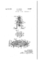
Fig 2 is al view infront elevation", certain 'parts being broken away and other parts being" shown` inV vertical section g Figi 3 is a vertical section Vtaken on line '3`-3-0,f Figs2; Y .Y 4 is a horizontal section on line 4-4 -ofFig`.3;andN Y f Fig. 5 is a horizontal section taken on line 5.-'-5 of Fig. 3 shown on `an enlargedscale, lsaid sections being taken as indicated bythe arrows. fi j l 50 Referring to thedrawingsya machinelis showncomp'rising the jframe J10 of hollow MACHINE 192s! serial No. 269,919.
PATENT ioFFIcEig boxlike form havingl a surrounding bottom p ange 10a provided with spaced supporting lugs 1105. The fframe 10 'is'provided at one side ywith jthe dove-tailed ribs lOcforming the guidewayffor a .slide 11 fitting on said guideway and extending transversely"` of the machine.v The slide 11 has secured thereto a plate 12 having a-projecting boss 12a vin whichis journaled a screw 13, said screw being held from movement by the collar 14 pinned to said screw at one end of said bearing Vand by the operating handV wheel`1`5 disposed at thevother end ofsaidbearing and vheld in place by the nuts 16 threaded on the end of screw. 13. Thefscrewflpasses through a threaded portion of frame 10e whereby when hand wheel 15 is turned, slide 11 will be moved forwardly and rearwardly. The slide 11 has secured th'eretoby` bolts 17 `asaddle member 18 lin'which is mounted a'motor19. The motor -19 has secured'to one end of its armature or driving shaft 20 Y a grinding wheel 217 the sam-e being heldin place on an arbor 22 secured to said shaft by the' plate 23 vand clamping nuts'24. The said driving shaft20 has secured to its end a grooveddriving pulley 25 over which runs a belt^26 alsolrunning over and driving a pulley`527' keyed tof'one end of a splined shaft .28, thehubof said pulley being journaled I 4in `a depending portionpllavoflthe slide 11. The shaft 28 ,extendslthrough an aperture in the'cnd of framel() andis :jo'urn'aled at its A'other endin `one hub of a bearing 29 carried .Y V"on rand forming a vbearing forv `avertica'l 'shaft 3 0 extending upward `adjacent onev end of the frame 10. Gears 31and32 are respec-Y tively secured to lshafts 28an d 30, said gears meshing Vwith each other and forming the Y driving means Yfor shaft 30. Y The shaft '30 rhas secured thereto immediately'above bear# ing'29 an eccentric SS'disposed' in a slot 10g 1in Vframe 10 and extending transverselyfof the slide 34. The slide 34 is movablelength- 107i vformedon 'said frame. AThe slide 34 has anupstanding cylindrical portion' 84?) sub,-
wise of the frame'onfthe dove-'tailed guide 95 35 may be held in the desired position by a set screw 35?). The head 35 has spaced bearing portions 35a in which is journaled a hollow shaft 36. A cover 37 extends over and between the portions 37a being secured at its sides to the head 35 by the screws 38. The shaft 36 is tapered interiorly and exe teriorly at its end 36a and is threaded at its other end to receive asleeve 39. Knurled ornamental cap members are secured at the ends of bearing portions 35a` The shaft k36 is interiorly threaded at the end opposite end 36a to receive the threaded hub 41m-of a knurled Wheel 41 having a bore therethrough with a flared inner end. A clamping sleeve 42 is carried in shaft 36 having split tapered ends, said sleeve 42 forming .a holding means for the article to be ground, such as the stein 43al of a valve'43. The flared end of the bore in hub 41a engages the tapered vend of member 42 .and as member 41 is turned to move hub 41a inwardly, member 42 will be pushed against the tapered end 36a and vcontracted, and will also have its other .end contracted by the flared surface on member 41. The stem 4366 is thus firmly clamped Vat separated points and thus held accurately in axial posit-ion in shaft 36. The shaft 36 has secured thereto a gear 44 in any suitable manner as, by the set screw 45, which .gear meshes .with a pinion 46 secured to the top of the shaft 30. The slide 11 is provided with .a socket 47 adapted to receive the Vdetachable plug 48 to which are connected the conductors l49 for supplying current to. motor 19. Conductors -49 will be provided at their other ends with a plug which'can be inserted in any .convenient electric socket. The socket 47 will be connected by suitable conductors to a switch 50 `car ried in the frame and having a projecting operating handle 50a which will be disposed in convenient position 'for operation.
1n operation, currentwill be supplied to the motor 19 and the grinding wheel 21 will be rotated at high speed. The shaft 28 lis driven through belt 26. vShaft 30ris driven through gears v30` and 3l by .shaft 28. and shaft v3() in turn rotates the shaft 36 through the gear 44. The valve to be ground, such as shown Vat 43, will be clampedand centered in the member 42 by turning the wheel 41.. The head 35 will then be turned on member .34?) so that the valve 4occupies the proper position in relation to the edge of the wheel 21 and will` then be tightened and held in position by screw 35.29.r As the machine is now driven, shaft .3.0 will revolve eccentric 33' and thus will reciprocateslide 34 through a certain, amplitude so that the valve 43 will Abe moved back and forth across the wheel 21.
The valve will also be rotated by shaft 36 being rotated by the ,gear 4-6. The valve is thus turned and .simultaneously reciprocatedand the same will be properly and accurately .chineis quite small and is thus very convenient for small establishments such as garages, forl valve grinding purposes." In the commercial embodiment ofthemachine the base is approximately one foot long. rlhe machine has sufiicient weight so that it may simply rest on any suitable support and be operated without being secured thereto. The machine can be connected for loperation to any convenient lamp socket and 4nobelts are thus necessary. The Vparts are comparatively few, compactly arranged, and `so disposed that there are no moving parts in t-he way of the operator or in which the operator may be caught. The device has been amply demonstrated in actual practice and. found to bevery successful and eflicient.
It will, of course, be understood that various changes may be made in the form, details, arrangement and proportions of the parts, without departing from the scope of vapplicants invention, which, generally stated, consist-s in a device capable of carrying out the objects above set forth, in the novel parts and combinations of parts disclosed and defined in the appended claims.
l/Vhat is claimed is 1. A grinding machine having in combination, a frame, a slide movable transversely thereof, a motor. mounted on said slide, a grinding wheel secured to the rdriving shaft ofsaid motor and rotated thereby, a splined shaft extending longitudinally of said frame below said slide, a slide on said frame rreciprocable toward and from said grinding wheel parallel to the axis thereof, a head rotatable on said slide,.ja member journaled in said head adapted to hold an article to-be ground,I a gear secured to said member, a gear meshing with said gear, a shaft secured to said last mentioned gear and extending vertically through said head and slide, means on said shaft for reciprocating said last inentioned slide, a gear secured to said last men tioned shaft, a gear meshing'with said last mentioned gear and secured to said splined shaft, a pulley carried on said first mentioned slide through which said splined shaft projects, said pulley being keyed to said splined shaft, a pulley carried bysaid motor and abelt connecting said pulleys.
2. A valve grinding machine having .in
combination, a frame, a slide movable transversely of said frame, a motor carried on said slide, agrinding wheel carried on the shaft of said motor, a second slide" on said frame reciprocable parallel to the axis of said shaft and wheel, a head revoluble on said second slide about a vertical axis, a member journaled in said head about a horizontal axis' adapted to carry a valve to be ground, beveled gears for rotating said member, a vertical shaft carrying one of said gears and extending downwardly through said head into said frame, a beveled gear at the lower endof said shaft, means on said shaft for reciprocating said second slide, a beveled gear meshing with said beveled gear, a shaft securedto said -last mentioned beveled gear and extending lengthwise of said frame at the bottom thereof, a' pulley journaled in said Vframe at one end thereof and held from movement longitudinally of its axis, said last mentioned shaft being splined to said pulley and reciprocableV therein and a pulley on said motor, and a belt running over both of said pulleys. f 3. A valve grinding machine having in combination, a frame, a slide adjustable transversely ofsaid frame, a motor carried on said slide, a grinding wheel attached to the shaft of said motor, a work-carrying slide, slidable longitudinally of said frame in a line Y parallel to the axis of said motor shaft, a
work-carrying head rotatably adjustable on said work-carrying slide, a rotary chuck in said head journaled on a horizontal axis` a Y A 85 vertical driving shaft extending throughsaid head connected with said chuck for driving the same, driving connections between the lower end of said shaft and said motor and an eccentric-disposed medially of said shaft for slidably reciprocating said work-carrying slide.
In testimony whereof I aiiix my signature.
GUSTAVE F.v KRIESEL.
Priority Applications (1)
| Application Number | Priority Date | Filing Date | Title |
|---|---|---|---|
| US269919A US1853907A (en) | 1928-04-14 | 1928-04-14 | Grinding machine |
Applications Claiming Priority (1)
| Application Number | Priority Date | Filing Date | Title |
|---|---|---|---|
| US269919A US1853907A (en) | 1928-04-14 | 1928-04-14 | Grinding machine |
Publications (1)
| Publication Number | Publication Date |
|---|---|
| US1853907A true US1853907A (en) | 1932-04-12 |
Family
ID=23029162
Family Applications (1)
| Application Number | Title | Priority Date | Filing Date |
|---|---|---|---|
| US269919A Expired - Lifetime US1853907A (en) | 1928-04-14 | 1928-04-14 | Grinding machine |
Country Status (1)
| Country | Link |
|---|---|
| US (1) | US1853907A (en) |
Cited By (1)
| Publication number | Priority date | Publication date | Assignee | Title |
|---|---|---|---|---|
| US2911765A (en) * | 1953-07-20 | 1959-11-10 | Clara B Studler | Refacing machine |
-
1928
- 1928-04-14 US US269919A patent/US1853907A/en not_active Expired - Lifetime
Cited By (1)
| Publication number | Priority date | Publication date | Assignee | Title |
|---|---|---|---|---|
| US2911765A (en) * | 1953-07-20 | 1959-11-10 | Clara B Studler | Refacing machine |
Similar Documents
| Publication | Publication Date | Title |
|---|---|---|
| US2334938A (en) | Cam grinding machine | |
| US1853907A (en) | Grinding machine | |
| US1781674A (en) | Automatic planer-knife grinder | |
| GB663815A (en) | Improvements in grinding machines | |
| US1440386A (en) | Polishing and grinding machine | |
| US1806664A (en) | A corpora | |
| US1202400A (en) | Valve-grinder. | |
| US2827804A (en) | Power shift device for machinery | |
| US1345374A (en) | Polishing-machine | |
| US1599956A (en) | Polishing machine | |
| US1388884A (en) | Valve-grinding machine | |
| US1146684A (en) | Universal stoneworking-machine. | |
| US1418863A (en) | Buffing machine | |
| US1575694A (en) | Grinding and polishing machine | |
| US748339A (en) | Grinding-machine. | |
| US1375343A (en) | Grindstone | |
| US1481999A (en) | Billiard-cue machine | |
| US1368263A (en) | Edge-beveling machine | |
| US2305107A (en) | Belt milling and grinding machine | |
| US1352583A (en) | Machine | |
| US1502136A (en) | Glass-polishing machine | |
| US1404691A (en) | Roll-grinding mechanism | |
| US1178036A (en) | Grinding-machine. | |
| US1544287A (en) | Grinding machine | |
| US437747A (en) | barber |