US1853890A - Propeller - Google Patents
Propeller Download PDFInfo
- Publication number
- US1853890A US1853890A US578706A US57870631A US1853890A US 1853890 A US1853890 A US 1853890A US 578706 A US578706 A US 578706A US 57870631 A US57870631 A US 57870631A US 1853890 A US1853890 A US 1853890A
- Authority
- US
- United States
- Prior art keywords
- propeller
- shaft
- primary
- hub
- gear
- Prior art date
- Legal status (The legal status is an assumption and is not a legal conclusion. Google has not performed a legal analysis and makes no representation as to the accuracy of the status listed.)
- Expired - Lifetime
Links
- XLYOFNOQVPJJNP-UHFFFAOYSA-N water Substances O XLYOFNOQVPJJNP-UHFFFAOYSA-N 0.000 description 6
- 239000000446 fuel Substances 0.000 description 5
- 238000010276 construction Methods 0.000 description 4
- 239000012530 fluid Substances 0.000 description 2
- 239000000314 lubricant Substances 0.000 description 2
- 241000982285 Adansonia rubrostipa Species 0.000 description 1
- 102000017795 Perilipin-1 Human genes 0.000 description 1
- 108010067162 Perilipin-1 Proteins 0.000 description 1
- 230000002349 favourable effect Effects 0.000 description 1
- 230000007775 late Effects 0.000 description 1
Images
Classifications
-
- B—PERFORMING OPERATIONS; TRANSPORTING
- B63—SHIPS OR OTHER WATERBORNE VESSELS; RELATED EQUIPMENT
- B63B—SHIPS OR OTHER WATERBORNE VESSELS; EQUIPMENT FOR SHIPPING
- B63B3/00—Hulls characterised by their structure or component parts
- B63B3/14—Hull parts
- B63B3/40—Stern posts; Stern frames
-
- B—PERFORMING OPERATIONS; TRANSPORTING
- B63—SHIPS OR OTHER WATERBORNE VESSELS; RELATED EQUIPMENT
- B63H—MARINE PROPULSION OR STEERING
- B63H1/00—Propulsive elements directly acting on water
- B63H1/02—Propulsive elements directly acting on water of rotary type
- B63H1/12—Propulsive elements directly acting on water of rotary type with rotation axis substantially in propulsive direction
- B63H2001/122—Single or multiple threaded helicoidal screws, or the like, comprising foils extending over a substantial angle; Archimedean screws
- B63H2001/125—Single or multiple threaded helicoidal screws, or the like, comprising foils extending over a substantial angle; Archimedean screws with helicoidal foils projecting from outside surfaces of floating rotatable bodies, e.g. rotatable, cylindrical bodies
-
- B—PERFORMING OPERATIONS; TRANSPORTING
- B63—SHIPS OR OTHER WATERBORNE VESSELS; RELATED EQUIPMENT
- B63H—MARINE PROPULSION OR STEERING
- B63H5/00—Arrangements on vessels of propulsion elements directly acting on water
- B63H5/07—Arrangements on vessels of propulsion elements directly acting on water of propellers
- B63H5/08—Arrangements on vessels of propulsion elements directly acting on water of propellers of more than one propeller
- B63H5/10—Arrangements on vessels of propulsion elements directly acting on water of propellers of more than one propeller of coaxial type, e.g. of counter-rotative type
- B63H2005/106—Arrangements on vessels of propulsion elements directly acting on water of propellers of more than one propeller of coaxial type, e.g. of counter-rotative type with drive shafts of second or further propellers co-axially passing through hub of first propeller, e.g. counter-rotating tandem propellers with co-axial drive shafts
-
- B—PERFORMING OPERATIONS; TRANSPORTING
- B63—SHIPS OR OTHER WATERBORNE VESSELS; RELATED EQUIPMENT
- B63H—MARINE PROPULSION OR STEERING
- B63H23/00—Transmitting power from propulsion power plant to propulsive elements
- B63H23/02—Transmitting power from propulsion power plant to propulsive elements with mechanical gearing
- B63H2023/0283—Transmitting power from propulsion power plant to propulsive elements with mechanical gearing using gears having orbital motion
-
- B—PERFORMING OPERATIONS; TRANSPORTING
- B63—SHIPS OR OTHER WATERBORNE VESSELS; RELATED EQUIPMENT
- B63H—MARINE PROPULSION OR STEERING
- B63H23/00—Transmitting power from propulsion power plant to propulsive elements
- B63H23/02—Transmitting power from propulsion power plant to propulsive elements with mechanical gearing
- B63H23/06—Transmitting power from propulsion power plant to propulsive elements with mechanical gearing for transmitting drive from a single propulsion power unit
- B63H2023/062—Transmitting power from propulsion power plant to propulsive elements with mechanical gearing for transmitting drive from a single propulsion power unit comprising means for simultaneously driving two or more main transmitting elements, e.g. drive shafts
- B63H2023/067—Transmitting power from propulsion power plant to propulsive elements with mechanical gearing for transmitting drive from a single propulsion power unit comprising means for simultaneously driving two or more main transmitting elements, e.g. drive shafts the elements being formed by two or more coaxial shafts, e.g. counter-rotating shafts
-
- B—PERFORMING OPERATIONS; TRANSPORTING
- B63—SHIPS OR OTHER WATERBORNE VESSELS; RELATED EQUIPMENT
- B63H—MARINE PROPULSION OR STEERING
- B63H23/00—Transmitting power from propulsion power plant to propulsive elements
- B63H23/32—Other parts
- B63H23/34—Propeller shafts; Paddle-wheel shafts; Attachment of propellers on shafts
- B63H2023/342—Propeller shafts; Paddle-wheel shafts; Attachment of propellers on shafts comprising couplings, e.g. resilient couplings; Couplings therefor
Definitions
- PROPELLER v Filed Dec. 3, 1931 Patented Apr.'Y 12, 1932 ⁇ UNITED-STA i PAUL AUGNER, or rrmLAniizLrHLA, PnivivsYLvANIAj f PROPELLER Application inea December 3, 1931. serialv No'. 578,706. i
- My invention relates to new and useful improvements in a propeller andwhile the illustration and ⁇ description will relate its use in A connection with a ship ythattravels in water,
- Y l provide a systemv of propelling ships which Y vide a secondary propeller 'in combinationV consists'in utilizing the swirling currents of fluid, either water or air, discharged by the primary propeller against a secondary ⁇ pro ⁇ power peller andl then transferring the created by the secondary propeller back tothe primary propeller in order tov create more vpower then generated by .the prime mover in order to VrevolveV therprimary propeller at greater speed or at va predetermined speed with less power from the prime mover so as to bring about a saving in fuel.
- Y vide a secondary propeller 'in combinationV consists'in utilizing the swirling currents of fluid, either water or air, discharged by the primary propeller against a secondary ⁇ pro ⁇ power peller andl then transferring the created by the secondary propeller back tothe primary propeller in order tov create more vpower then generated by .the prime mover in order to VrevolveV therprimary propeller at greater speed or at va predetermined
- Another object of the invention is to prowith a primary propeller with means for transmittinginiotion from the secondarypropeller to the primary oner' Another object of the invention is to provide two propellers in endwise alignment, one
- a further object ofthe invention is to proincrease the propelling power to such an extent that aship equipped with the invention claims.
- Y v p Y v In order thattho'se skilled inthe art toY will. have increased ⁇ speed,j but if not utilized will be aV for increasing the-speed then'there considerable saving in fuel.
- this invention'j consists in the details of construction 1 andcombinati'on of elements hereinafter set specifically designated by the 'f ⁇ shaft to vpermit rotationv of the hub orshell forth .and then 'which this invention appertains may understand how to vmake use the same, I will describeA its construction in detail, *referring thelinesof an oldV ship, l, shaft 8 Ais provided whichgisl connected to the stern end of the shaft 6 in endwise alignment Vby means of a suitablecoupling 9.
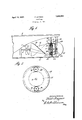
- Fig. l is a conventional side elevationf'of the stern of a ship or boatshowing my invention applied thereto with parts broken away -55 and shown ⁇ in section to illustrate details-"of construction.
- Fig. 2 is anenla'rged face view ofthetrain of gears used for transmitting power from the secondary tothe primary propeller.
- '5 represents a ship herein Villustrated'as a boat which travels in or onthe Y water and in ,which the prime' mover (notV Y.
- this .shaft may be ofsuicient length to extend well to the vstern of the pro-A peller 7 but where the invention plied to an old ship or one constructed along lthen Yan auxiliary flanges fixed to the meetingends of the shaft 6 land its extension 'orfauxiliaryf shaft ⁇ 8l'and the two fla'ng'esbolted'together.
- Thestern end ofthe shaft, whetherin one piece orv produced from ,the ⁇ original shaft and an extensionor auxiliary, is journalled in a suitableupright 10 located betweenfand fixed to the 'overhanging stern of the ship body or hull and a *keel'extensi'on 11.
- Any usual rudder Al2 may be; provided and, located Y to thestern of the upright 10.
- c f A frusto-conical hub o r shell 14 is mounted upon orsurrounds a portion of the shaft to the stern of the 'primary propeller A7 with the y smaller end vof said hub or shell projecting ⁇ forwardly and Ajournalled upon the lshaft
- vthels'trger or Vstern end or base ofsaid hub or, ⁇ shell A is fixed to the endsof'a cross piece or bar ⁇ -15 which'is j ournalled upon the -relative to said shaft or vice versa.
- Any Y number of helixes '16 are carried bythe hub is to be ap- 'zo in the ordinary manner that the ship is proceeding, it will have a forwardly boring action.
- a spur gear 17 meshing with a pair of pinions 18 which are located across the gear 17 at diametrically opposite points and j ournalled on axles 19, the ends of which are mounted in the circular plates or discs 20, one of which is located on each or toward each face of the gear 17 and in order to add rigidity to the parts and cause said circular lates or discs to revolve with the secondary propeller they may be attached to the cross Y piece or bar by means of the axles 19 or otherwise.
- an internal ring gear 21 which is secured by abolt 22 or other suitable fastening means to a bracket 23 which in turn is fixed to some part of the shipI for instance to the heel extension 11.
- This internal ring gear is further braced to prevent rotation and maintain its setting with relation to the gear 17 and pinion 18 by a cap 24 which fits over the circular plates or discs 2O and is joined in a water tight manner with the larger end of the hub or shell 14 and said cap and internal ring gear are secured together by fastening means 25, such as screws, passing through the ange of the cap and threaded into the gear.
- the cap 24 is fashioned so as to fit over the propeller shaft and the bracket 23 and is rigidly held in place by any desirable number of bolts or equivalent fastening devices 26 passing through the Aupright 10 andhaving threaded connection with the endwall of said lin order to lubricate the gearing, a tube 27 may be provided and'may run from the inside of the stern of the vship or from any other locality to the chamber within the hub 14 and its cap 24 or to the side of the train of gears through the cap.
- the space between said circular plates or discs may be utilized as a lubricant chamber so that the gears can be submerged in a suitable lubricant if necessary.
- the operation is as follows: The prime mover within the ship transmitting power y h ll sh ft 'll s th ⁇ rimar to t e prope er a W1 eau e e P 5% holding the same rigidly in place including a Acap partially enclosing propeller 7 to revolve. The revolution o the primary propeller will produce swirling revolving water currents and it might beV said thatthesefare discharged by the primary propeller.
- Such currents impinginst the helixes or convolute 'blades f 16 of the secondaryV pro-peller will cause the latter to revolve andcompel the pinions 18 which are connected with the secondary pro -volving the primary peller to walk around theinternal ring gear 21 which is stationary and thus transmit power to the spur 17 so that the latter will revolve in the same direction as the propeller shaft and being fixed to said propeller shaft will assist in revolving the latter thereby adding a certain amount of power to the pro-peller shaft which may be utilized to increase the number of revolutions of the primary propeller 7 or to assist the prime mover in re propeller at the predetermined rate of speed whereby less power is actually required from the prime mover and therefore a saving in fuel is obtained.
- a propellerV shaft including an extension rigidly connected therewith in endwise alignment, an upright to support the stern end of the extension, a secondary propeller jourf nailed upon the shaft extension, a spur gear iixed to the shaft extension, a pair of discs one on each side of the spur gear, axles mounted in said discs, pinions journalled on said axles and meshing with the spur gear said pinions, axles and discs being supported by and revolving with the secondary propeller, an internal ring 4gear enclosing and meshing the pinions and means to assist inl fixed my signature.
Description
P. AUGNER April 12, 1932.
PROPELLER v Filed Dec. 3, 1931 Patented Apr.'Y 12, 1932` UNITED-STA i PAUL AUGNER, or rrmLAniizLrHLA, PnivivsYLvANIAj f PROPELLER Application inea December 3, 1931. serialv No'. 578,706. i
My invention relates to new and useful improvements in a propeller andwhile the illustration and` description will relate its use in A connection with a ship ythattravels in water,
I do not intend to limitthe use of such propeller since it may be applied to airships.
One of the objects ofmy invention is to Y lprovide a systemv of propelling ships which Y vide a secondary propeller 'in combinationV consists'in utilizing the swirling currents of fluid, either water or air, discharged by the primary propeller against a secondary `pro` power peller andl then transferring the created by the secondary propeller back tothe primary propeller in order tov create more vpower then generated by .the prime mover in order to VrevolveV therprimary propeller at greater speed or at va predetermined speed with less power from the prime mover so as to bring about a saving in fuel. Y
Another object of the invention is to prowith a primary propeller with means for transmittinginiotion from the secondarypropeller to the primary oner' Another object of the invention is to provide two propellers in endwise alignment, one
- of which is mounted upon a shaft torevolve` therewith and the other'journalled to revolve said shaft and receiving'its power from cur- 5'- 30 rents of fluid produced by the primary pro-l peller and a train lof gearing so arranged'that -the powerdev'eloped by the secondary Vpro'- vide a system of propelling shipswhich will peller will betransferredto the shaft and thence to the primary propeller. l v. .Y A further object ofthe invention is to proincrease the propelling power to such an extent that aship equipped with the invention claims. Y v p Y v In order thattho'se skilled inthe art toY will. have increased` speed,j but if not utilized will be aV for increasing the-speed then'there considerable saving in fuel.
With theseand other ends in view', this invention'jconsists in the details of construction 1 andcombinati'on of elements hereinafter set specifically designated by the 'f `shaft to vpermit rotationv of the hub orshell forth .and then 'which this invention appertains may understand how to vmake use the same, I will describeA its construction in detail, *referring thelinesof an oldV ship, l, shaft 8 Ais provided whichgisl connected to the stern end of the shaft 6 in endwise alignment Vby means of a suitablecoupling 9. .K The cou-` 75 plin'g illustratedislproduced from companion or shell 14 Aand withthe latter form a second- .v ary lpropeller so curvedthat when 'revolving` by numerals to the accompanying drawings forming a partof this application, in which: Fig. l is a conventional side elevationf'of the stern of a ship or boatshowing my invention applied thereto with parts broken away -55 and shown `in section to illustrate details-"of construction.' 7 Y Y Fig. 2 is anenla'rged face view ofthetrain of gears used for transmitting power from the secondary tothe primary propeller. 60
Y In carrying out my invention as herein embodied, '5 represents a ship herein Villustrated'as a boat which travels in or onthe Y water and in ,which the prime' mover (notV Y.
vIn building a new shipwhich is to embody "my invention, this .shaft may be ofsuicient length to extend well to the vstern of the pro-A peller 7 but where the invention plied to an old ship or one constructed along lthen Yan auxiliary flanges fixed to the meetingends of the shaft 6 land its extension 'orfauxiliaryf shaft` 8l'and the two fla'ng'esbolted'together. Thestern end ofthe shaft, whetherin one piece orv produced from ,the` original shaft and an extensionor auxiliary, is journalled in a suitableupright 10 located betweenfand fixed to the 'overhanging stern of the ship body or hull and a *keel'extensi'on 11. Any usual rudder Al2 may be; provided and, located Y to thestern of the upright 10. c f A frusto-conical hub o r shell 14 is mounted upon orsurrounds a portion of the shaft to the stern of the 'primary propeller A7 with the y smaller end vof said hub or shell projecting `forwardly and Ajournalled upon the lshaft Whilevthels'trger or Vstern end or base ofsaid hub or,` shell Ais fixed to the endsof'a cross piece or bar`-15 which'is j ournalled upon the -relative to said shaft or vice versa. Any Y number of helixes '16 are carried bythe hub is to be ap- 'zo in the ordinary manner that the ship is proceeding, it will have a forwardly boring action.
To the stern of the secondary propeller and in fact to the stern of the cross piece or bar 15 in spaced relation thereto and fixed to the shaft is a spur gear 17 meshing with a pair of pinions 18 which are located across the gear 17 at diametrically opposite points and j ournalled on axles 19, the ends of which are mounted in the circular plates or discs 20, one of which is located on each or toward each face of the gear 17 and in order to add rigidity to the parts and cause said circular lates or discs to revolve with the secondary propeller they may be attached to the cross Y piece or bar by means of the axles 19 or otherwise. Y
Located between the circular plates or discs 20 and surrounding the aforementioned gears so as to mesh with tliepinions 18 is an internal ring gear 21 which is secured by abolt 22 or other suitable fastening means to a bracket 23 which in turn is fixed to some part of the shipI for instance to the heel extension 11. This internal ring gear is further braced to prevent rotation and maintain its setting with relation to the gear 17 and pinion 18 by a cap 24 which fits over the circular plates or discs 2O and is joined in a water tight manner with the larger end of the hub or shell 14 and said cap and internal ring gear are secured together by fastening means 25, such as screws, passing through the ange of the cap and threaded into the gear.
The cap 24 is fashioned so as to fit over the propeller shaft and the bracket 23 and is rigidly held in place by any desirable number of bolts or equivalent fastening devices 26 passing through the Aupright 10 andhaving threaded connection with the endwall of said lin order to lubricate the gearing, a tube 27 may be provided and'may run from the inside of the stern of the vship or from any other locality to the chamber within the hub 14 and its cap 24 or to the side of the train of gears through the cap. By making oil tight joints between the circular plates or discs 20 and the cap 24, the space between said circular plates or discs may be utilized as a lubricant chamber so that the gears can be submerged in a suitable lubricant if necessary.
ing aga The operation is as follows: The prime mover within the ship transmitting power y h ll sh ft 'll s th` rimar to t e prope er a W1 eau e e P 5% holding the same rigidly in place including a Acap partially enclosing propeller 7 to revolve. The revolution o the primary propeller will produce swirling revolving water currents and it might beV said thatthesefare discharged by the primary propeller. Such currents impinginst the helixes or convolute 'blades f 16 of the secondaryV pro-peller will cause the latter to revolve andcompel the pinions 18 which are connected with the secondary pro -volving the primary peller to walk around theinternal ring gear 21 which is stationary and thus transmit power to the spur 17 so that the latter will revolve in the same direction as the propeller shaft and being fixed to said propeller shaft will assist in revolving the latter thereby adding a certain amount of power to the pro-peller shaft which may be utilized to increase the number of revolutions of the primary propeller 7 or to assist the prime mover in re propeller at the predetermined rate of speed whereby less power is actually required from the prime mover and therefore a saving in fuel is obtained. My experiments with this propeller have been carried on in motor boat 11,5014 and the ratio and arrangements of `the parts were such that the primary propeller made 100 R. P. M., while the secondary propeller made 40 R. l?. M. The secondary propeller gradually increased the speed of the primary propeller to 130 R. P. M. without any additional power on the prime mover and under generally the same conditions at which the primary propeller would only make 100 R. P. M. under the most favorable conditions. Thus it is obvious with the same'amount of fuel used in the prime mover, a greater amount of power is applied to the propeller shaft so as to increase the speed o-f the shipV or at a predetermined speed the amount of fuel necessary to operate the prime mover may be considerably reduced. Y
Of course I do not wish to be limited to the exact details of construction herein shown and described as these may be varied within the limits of the appended claims withoutdeparting from the spirit of my invention.
Having thus fully described my invention7 what I claim as new and useful is: Y 1. In` a device of the character described, a propellerV shaft including an extension rigidly connected therewith in endwise alignment, an upright to support the stern end of the extension, a secondary propeller jourf nailed upon the shaft extension, a spur gear iixed to the shaft extension, a pair of discs one on each side of the spur gear, axles mounted in said discs, pinions journalled on said axles and meshing with the spur gear said pinions, axles and discs being supported by and revolving with the secondary propeller, an internal ring 4gear enclosing and meshing the pinions and means to assist inl fixed my signature.
the primary propeller and helix blades on said hub.
3. The combination of a ship, a propeller shaft revolved by a prime mover, a primary propeller fixed to said shaft, a secondary propeller journalled on said shaft to the stern of the primary propeller and including a frusto-conioal hub, the smaller end of Which is contiguous the primary propellerhelix blades on said hub anda bar projecting across the larger end of the hub and jour nalled on the propeller shaft, a spur gear Jixed on said propellershaft to the stern of the secondary propeller, a plate on each side of said spur gear, axles xed to said plates and said plate assembly being fixed to the bar on the `secondary propeller, pinions journalled on said axles and meshingV With the spur gear, an internal ringy gear enclosing the pinions and meshing therewith, a keel extension, a bracket fixed to said keel/and the ring gear to assist in holding said ring gear stationary, an upright Vbetween the overhanging stern of the ship and the keel extension and acting as a bearing for the outer end of the propeller shaft, a cap projected over the plate and gear assembly and providing a Water tight joint with the hub of the secondary propeller, means to connect said cap `and ring gear, means co-acting With said cap and the upright to hold said cap sta' tionary and rigid and means to lubricate the gear assembly. Y
In testimony whereof, I have hereunto af- PAUL AUGNER.
Priority Applications (1)
| Application Number | Priority Date | Filing Date | Title |
|---|---|---|---|
| US578706A US1853890A (en) | 1931-12-03 | 1931-12-03 | Propeller |
Applications Claiming Priority (1)
| Application Number | Priority Date | Filing Date | Title |
|---|---|---|---|
| US578706A US1853890A (en) | 1931-12-03 | 1931-12-03 | Propeller |
Publications (1)
| Publication Number | Publication Date |
|---|---|
| US1853890A true US1853890A (en) | 1932-04-12 |
Family
ID=24313950
Family Applications (1)
| Application Number | Title | Priority Date | Filing Date |
|---|---|---|---|
| US578706A Expired - Lifetime US1853890A (en) | 1931-12-03 | 1931-12-03 | Propeller |
Country Status (1)
| Country | Link |
|---|---|
| US (1) | US1853890A (en) |
Cited By (3)
| Publication number | Priority date | Publication date | Assignee | Title |
|---|---|---|---|---|
| US2568903A (en) * | 1949-07-02 | 1951-09-25 | Irvin Dowell J | Propeller construction for watercraft |
| US4571192A (en) * | 1983-11-09 | 1986-02-18 | Allied Corporation | Self propelled spherical vehicle |
| US5447111A (en) * | 1993-07-29 | 1995-09-05 | Ning; Jianjin | Rotor type energy saving apparatus mounted on the bow |
-
1931
- 1931-12-03 US US578706A patent/US1853890A/en not_active Expired - Lifetime
Cited By (3)
| Publication number | Priority date | Publication date | Assignee | Title |
|---|---|---|---|---|
| US2568903A (en) * | 1949-07-02 | 1951-09-25 | Irvin Dowell J | Propeller construction for watercraft |
| US4571192A (en) * | 1983-11-09 | 1986-02-18 | Allied Corporation | Self propelled spherical vehicle |
| US5447111A (en) * | 1993-07-29 | 1995-09-05 | Ning; Jianjin | Rotor type energy saving apparatus mounted on the bow |
Similar Documents
| Publication | Publication Date | Title |
|---|---|---|
| US2064195A (en) | Propulsion unit | |
| US1813552A (en) | Propelling mechanism | |
| US938911A (en) | Propelling means for vessels. | |
| GB1163549A (en) | Propellers for Marine Vessels, Land Vehicles and Aircraft | |
| US1853890A (en) | Propeller | |
| US1921893A (en) | Propelling device | |
| US2393234A (en) | Contraturning propeller mechanism | |
| US2322014A (en) | Ship propulsion | |
| US2246539A (en) | Variable pitch propeller | |
| US2162058A (en) | Boat | |
| US1049661A (en) | Motor-boat. | |
| US2196706A (en) | Watercraft | |
| US1119178A (en) | Propeller and driving means therefor. | |
| US2263449A (en) | Airplane | |
| US2306840A (en) | Propeller system | |
| US1386835A (en) | Regenerative counter-propeller for marine vessels | |
| US355682A (en) | gowles | |
| US968823A (en) | Propelling device. | |
| US655699A (en) | Ship's propeller. | |
| US1853158A (en) | Vessel stern | |
| GB332124A (en) | Improvements in screw propulsion | |
| US1548554A (en) | Multistage toothed wheel gearing for the propulsion of ships by means of steam turbines | |
| US1905162A (en) | Stern paddle-wheel propulsion mechanism for boats | |
| US1088080A (en) | Driving mechanism for torpedoes. | |
| GB211927A (en) | Improvements in or relating to screw propelled navigable vessels |