US1853887A - Lifting coupler for containers and the like - Google Patents
Lifting coupler for containers and the like Download PDFInfo
- Publication number
- US1853887A US1853887A US477964A US47796430A US1853887A US 1853887 A US1853887 A US 1853887A US 477964 A US477964 A US 477964A US 47796430 A US47796430 A US 47796430A US 1853887 A US1853887 A US 1853887A
- Authority
- US
- United States
- Prior art keywords
- frame
- shackles
- container
- coupler
- lifting
- Prior art date
- Legal status (The legal status is an assumption and is not a legal conclusion. Google has not performed a legal analysis and makes no representation as to the accuracy of the status listed.)
- Expired - Lifetime
Links
- 230000035939 shock Effects 0.000 description 4
- 230000000284 resting effect Effects 0.000 description 3
- 230000000694 effects Effects 0.000 description 1
- 238000001513 hot isostatic pressing Methods 0.000 description 1
Images

Classifications
-
- B—PERFORMING OPERATIONS; TRANSPORTING
- B66—HOISTING; LIFTING; HAULING
- B66C—CRANES; LOAD-ENGAGING ELEMENTS OR DEVICES FOR CRANES, CAPSTANS, WINCHES, OR TACKLES
- B66C1/00—Load-engaging elements or devices attached to lifting or lowering gear of cranes or adapted for connection therewith for transmitting lifting forces to articles or groups of articles
- B66C1/10—Load-engaging elements or devices attached to lifting or lowering gear of cranes or adapted for connection therewith for transmitting lifting forces to articles or groups of articles by mechanical means
- B66C1/62—Load-engaging elements or devices attached to lifting or lowering gear of cranes or adapted for connection therewith for transmitting lifting forces to articles or groups of articles by mechanical means comprising article-engaging members of a shape complementary to that of the articles to be handled
- B66C1/66—Load-engaging elements or devices attached to lifting or lowering gear of cranes or adapted for connection therewith for transmitting lifting forces to articles or groups of articles by mechanical means comprising article-engaging members of a shape complementary to that of the articles to be handled for engaging holes, recesses, or abutments on articles specially provided for facilitating handling thereof
- B66C1/663—Load-engaging elements or devices attached to lifting or lowering gear of cranes or adapted for connection therewith for transmitting lifting forces to articles or groups of articles by mechanical means comprising article-engaging members of a shape complementary to that of the articles to be handled for engaging holes, recesses, or abutments on articles specially provided for facilitating handling thereof for containers
Definitions
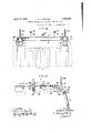
- IH represents anl endl elevation of the rowsfon.
- the booster weights 22 are in a relation to the the force due to the weight of the booster weights increases an amount equivalent to the decrease in force due to the weight of the load engaging members as the load engaging members Eswing downward towards the container 'hooks
- the magnetic brakes are shown mounted on plates 25 cencomprise in general a solenoid 26, ⁇ the plunger 27 of which is linked to brake shoes 28, and a spring 29 tending to apply the brake shoes to the disk 30. IVhen the solenoid is energized, the .shoes 28 are drawn apart by the plunger 27 acting through levers 31, 32 and 33.
- the function of the brakes 4- is to maintain the opposite pairs of shackles 2 in spread'position.
- the brakes being magnetically applied can be operated from a remote station, and the controllingA switch is preferably located within convenicnt reach of the hoist operator.
- hoisting ⁇ apparatus To raise and lower the frame 1, various types of hoisting ⁇ apparatus may be employed.y and I preferably use a traveling-crane provided with drums from which the cables 14: are suspended. In such manner the lifting coupler can'be kept level and square with the lot of containers.
- springs 34 and 35 Mounted also on the frame 1 are springs 34 and 35 above and below the horizontal flanges 36 of the side pieces 7.
- A. bolt 3T passes through each set of springs' and lioins the arm 38 of the bell crank lever 13-with a pivotal connection 39.
- the springs 34c ⁇ and 35 serve to absorb the shock incident to the application of the load to the frame when the container is raised fromits platform, the shock being transmitted to the springs through the shackles 2 ⁇ andthe bell crank levers 13.
- the lifting coupler When it is desired to shift the position of the container, the lifting coupler is transferred by means of the overhead crane to a point directly above the container.
- the lifting coupler with its magnetic brakes 4 applied and the shackles 2 held in the .spread position shown in Fig. II, is lowered to the top of the container to be lifted and guided so that the shackles will rest on the top edges of the container adjacent the hooks 6.
- the brakes l are then simultaneously released by energizing their magnets by a .switch at the hoist operators station.
- pivotal points ofthe load ene@ Upon striking the ISO by applying the remote controlled brakes, when it is desired to release the lifting coupler from a container, while the shackles 2 are in outwardly spread position.
- va'- tions froin said frame to an overheadhoist-V ing apparatus, load engaging members piv-V otally mounted on said frame at opposite sides thereof, a shaft link-connected to a load engaging member, a remote controlled brake for holding said shaft against rotation to maintain the load engaging members in a spread position, and ymeans on said framefor absorbing the initial shock incidentv to the lifting of 'the object from its resting place.
- an automatic lifting coupler comprising a frame substantially corresponding to the top of said container, and having connections to an overhead hoisting-apparatus, load engaging shackles pivotally mounted on said frame at lthe corners thereof and so spaced from each other asto cause said shackles to be guided by engagement with the top ofthe container into outwardly spread positions as said frameV is dropped centrallyupon the container andl to cause said shackles to fall into engagement with said hooks as said frame is raised, and means mounted on said frame for locking said shackles in outwardly spread positions.
- an automatic vlifting coupler comprising V ⁇ a frame substantially corresponding-to the top of said container, and having connections to an overhead hoisting apparatus, load engagingY shackles pivotally mounted on said frame at the corners thereof and so spaced Vfrom each otheras to cause said shackles tobe guided by enshackles whereby ⁇ theload is carried ⁇ direct to the hoisting apparatus.
- an automatic lifting coupler comprising a frame substantially corresponding to the top of said container, ⁇ and having connections to an overhead hoisting apparatus, load engaging shackles pivy otally mounted on said frame at the corners thereof and so spaced from each other as to cause said shackles to be-guided by. engagement with the top of the container into outwardly spread positions as said rframe is droppedcentrally upon the container and to cause said'shackles'to fall into engagement Y with said hooks as said framev is raised, and
- a lifting coupler comprising aframe,
- a lifting coupler comprising a. frame, load engaging members pivoted on said frame, means on said frame for maintaining said load engaging members in an outwardly spread position, said means including a brakeshaft and a linkage connecting said loadengaging membersvwith said-v shaft, and a booster weight mounted on said brake shaft in such angular relation to said load engaging members as to apply a maXimumVv of leverage when the load engaging.l members are in substantially-vertical position and a'minimumof leverage when the ,loadV engaging members are in spread position.
Landscapes
- Engineering & Computer Science (AREA)
- Mechanical Engineering (AREA)
- Load-Engaging Elements For Cranes (AREA)
Description
April l2, 1932. R. 1 sTlFFLER i 1,853,887
LIFT'NG COUPLER FOR CONTAINERS A ND THE LIKE Filed Aug. 26, 1930 2 Sheets-Sheet 4l FIG L TTORNE YS.
Patented pr. 12; 1932 l i f i l Y i i EAniaHI-rsrrrrtzniaaorALuiooNArENNsYnvANIA. E i
LETING? CGPLER`FOR-CONTANERSAND 'Y lThis` invention relatesito `lifting couplers couplerv adapted yfor nsevrwithY 'railroadiship andis esp'eciallyadapted tovconplers for li'ftpingcontalners; j Y y *y e j ing bodies such as railroad' hipping'containf Fig.V II represents aJ side: elevation'lof;the ers to facilitatetheir transfer 'from one" place same, showing also the' top` portion' of a con-V to another. Suchwcontainers arecustomarily tainer engaged by the coupler.'` 4 Y y,
accommodated side by side lin doubleor single IH represents anl endl elevation of the rowsfon. the l'oorofv a freight car, andllt Same/yan@ i r e positionthem properly Vnecessitates a hoistVL `Fg"' IV represents an enlargedr` erosssec=` v ingapparatus havingjprovison Jfor raising tionofra'partof tlievl'co'lupler taken-along theu v m lowerngand shifting a contaner'in a truly s lines I 'VIV of Fig. "I", showingjtlie load-. so Y vertical position square Withl respect to the engagllg members. in the position theyja's;v other containers resting on the'fl'oor of the Sumo When the load is engaged H i car. Otherwise,.considerable `difficulty is ex,- Y `r'.Ifhe apparatusl shown in' thedrzwvings'comi-Y perience'dvv in loweringV a container into its P'llSS generally*a'spacngffaiinl OfS'lbStlI :5, proper position, f tiallyrectangular shape,'load engaging'mem- 55' It hasheretofore been proposed to employ blS 2 llfpl the' form 'Oflf'sh'acklesf Apivotallyf frames separate from a, hoisting appa..l mllllted. afl] OllHI COl'llQI'S'zO ai. ratusfflor engagng'the top of' containers. tof brake shaft'3` link-connected@ theshackls facilitate their transfen: but such devices 2, and@ magnel bla'kg The frame 1c`or' have requiredv then services Voi`: a nnmber' of IGSpOilds roughly 1` 1jtS 'dlmeInISOyns tthe 70' men, and their usehas involVeddelays'in-the" ifetlrlfgulal" I 2111?@ the top of: tlieshippingf positioning of therliftng, frame abovethe 90m-amer 5iWlthHlgthe h0`0k's6 which areicontainsrs and' vthe securing ofthe'load enf 'locate/@119W 13h? @Olefs 0f the @Ontn'ef and," gagn-gvmembers to/ Proper-vfpontsof al1- are (llfelte(il. A
5 tachmenton thec'ontainers. Y ttedr the 'ame Compl-"ISGS" UW'OSde Pices; 76.
The principal object of the present inven-I 7'; 111 the OTHYG '&I1gl S, .21nd aiseresfotrans# tion istorprovide anautomatic` lifting cou* Verse channellbars 8' 30131115; @11? "Sdpiecesg pier separate'fromthe' hoisting apparatus loutl 7 at SPfWed' mtervlsfand irldrxSell'lell adapted to he positioned-above and to engagel theet? ,bymems 0f" angles lnvdv" gUSSeSl;
:su the load by means controlled from' thehoistf Prolectmg' QU'WT@ 3j Shot'dlstalfmm 80 ing station, so that the operations offhoisting,Y h @,Oinello the-frame l" @e Plates TNQ lowering', shifting ,engaging,and disengage A mp- @51de plece' Theplmeslcgy A ing` containers may' all ble' performedl loy'` a@ at t'leirfuternqs Pmsfm Whlchcserv? asfful' sin le individual; y Y i n crtims ior abell crank lever 13 andalso1 as=- 35' Anothen objectoff the invention is topro Pour@ Ofi attahmntfgr' thtvsspensnica" 55 View@aiiieing'coupler suchas described, 91.65141:.ThcablelMQ'QQDWWWWlh@ shock-absorbing means adaptedto', relieve the' pms '12h57 means'of yokesl which 'Simddle Y Y frame off ,ther coupler, of' the. initial *st-,rain- H Crmfleger 13? ssh-OWU@ 1.1L i
lyV attached thereto i an arml'lformingfwitli l Y inggthenventioniwill bemorefully apparent' asa. fu1'cmm y Y y Y having rflrene-to fh'exacompanyhg drawcmnk'iofon the* shafteithere islfa-'liffaor ingsgnnzwhich thereisi'llustratedfone enf1l od1''Y the form of@ tufnbuckle the ,length-5 ffwhih, mentonexampleoftheninyentionaf theV may be'var-ied toadjusttlieanglebetween-the V dj'12'avvf'ingse!il f l f' depending"shackle2V and the frame-11". 'c-'f fEigflrepresent's aplanv-iewfofaalitting cordingly, Vit Willy .be seen that Where*the'i fr @therr objects and advantages characterizg-,- :the shackle ,levepivted about tyifefp-n- 173 y i y load engaging member 2 such that trally of the shafts 3. rlhey shackles 2 at opposite sides of the container `are spread apart from the position shown in Fig. IV, to that shown in Fig. II, this will effect a turning movement ofr the shafts 3 within their bearings 21, the extent of rotation of the shafts 3 being indicated by the angle a b c, ofFig. IV, which represents the angular movement of weights 22 attached to the shafts 3 by arms 23. The booster weights 22 tend to maintain the shackles 2 ina substantially vertical position, .such as shown in' Fig. IV. `When the shackles 2 are in this position, the weight arms are in the position indicated by the line a ZJ, and a considerably greater leverage force isapplied to the shaft 3 than is ,the casewhen the shackles are in the spread position and the weight arms in the position indicated by the line Z) c. Thusthe booster weights 22 are in a relation to the the force due to the weight of the booster weights increases an amount equivalent to the decrease in force due to the weight of the load engaging members as the load engaging members Eswing downward towards the container 'hooks Associated with each shaft 3 is a remote controlled magneticbrake ll. The magnetic brakes are shown mounted on plates 25 cencomprise in general a solenoid 26,` the plunger 27 of which is linked to brake shoes 28, and a spring 29 tending to apply the brake shoes to the disk 30. IVhen the solenoid is energized, the .shoes 28 are drawn apart by the plunger 27 acting through levers 31, 32 and 33. When the solenoid is cle-energized, the spring 29 forces the levers 33 together, bringing the brake shoes in contact with the disk 30, and thus holding the shaft 3 against rotation.V The function of the brakes 4- is to maintain the opposite pairs of shackles 2 in spread'position. 'The brakes being magnetically applied can be operated from a remote station, and the controllingA switch is preferably located within convenicnt reach of the hoist operator.
To raise and lower the frame 1, various types of hoisting` apparatus may be employed.y and I preferably use a traveling-crane provided with drums from which the cables 14: are suspended. In such manner the lifting coupler can'be kept level and square with the lot of containers.
Mounted also on the frame 1 are springs 34 and 35 above and below the horizontal flanges 36 of the side pieces 7. A. bolt 3T passes through each set of springs' and lioins the arm 38 of the bell crank lever 13-with a pivotal connection 39. The springs 34c`and 35 serve to absorb the shock incident to the application of the load to the frame when the container is raised fromits platform, the shock being transmitted to the springs through the shackles 2 `andthe bell crank levers 13.
. so spaced from Veach other The operation of the lifting coupler is as follows: When it is desired to shift the position of the container, the lifting coupler is transferred by means of the overhead crane to a point directly above the container. The lifting coupler, with its magnetic brakes 4 applied and the shackles 2 held in the .spread position shown in Fig. II, is lowered to the top of the container to be lifted and guided so that the shackles will rest on the top edges of the container adjacent the hooks 6. The brakes l are then simultaneously released by energizing their magnets by a .switch at the hoist operators station. Upon the release of the brakes from the shafts 3, and the subsequent raising of the frame 1, the weight of the shackles 2 assisted by the weights 22 turns the shafts and the shackles 2 through the links 2O until the shackles assume the position lshown in Fig. IV. As the shackles are tius drawn together and the lifting coupler raised, the shackles fall into engagement with the hooks 6 and the container is lifted from its platform. After the container has been transferred to the proper point, it is lowered to the platform. y platform a. further lowering of the lifting coupler, due to the weight ofthe frame 1 and the contour fof the top of the container 5, causes the shackles to be spread apart and to disengage the hooks 6. When the shackles are thus spread, the brakes i are applied by opening the switch at the operators station and cle-energizing their magnets. With the shackles spread and the brakes applied, the Coupler is in readiness to engage the next container.
It will be observed that the cables bywhichV the lifting coupler is suspended join the frame at the gaging members. and that accordingly the ratus, only a. small fraction of the ,load being actually carried by theV frame. v
From the above description of the operation of the lifting coupler of this invention, it will be apparentl that the engagement or disengagement between the shackles 2 of the lifting coupler and the hooks 6 of the cone tainer is effected automatically by the raising and lowering ofthe frame 1, the pivotal points of lthe load engaging shackles 2'being as to cause the shackles to be guided by engagement with the top of the container into outwardly spread positions beyond the hooks 6 as the framef is dropped centrally upon the container, and to cause the shackles to fall of their own weight, assisted -by the weights y22, into engagement with .the hooks as the frame isV raised.- Accordingly, it is unnecessary toV provide mechanism for moving the container hooks, and the operator controls the entire operation of the lifting coupler merely by raising and lowering the frame thereof, and
pivotal points ofthe load ene@ Upon striking the ISO by applying the remote controlled brakes, when it is desired to release the lifting coupler from a container, while the shackles 2 are in outwardly spread position.
While I have described my invention in some detail with reference to a specific embodiment thereof, it will be apparent that va'- tions froin said frame to an overheadhoist-V ing apparatus, load engaging members piv-V otally mounted on said frame at opposite sides thereof, a shaft link-connected to a load engaging member, a remote controlled brake for holding said shaft against rotation to maintain the load engaging members in a spread position, and ymeans on said framefor absorbing the initial shock incidentv to the lifting of 'the object from its resting place. f y
2. In combination with a rectangular container having outwardly directed hooks near thetop corners thereof, an automatic lifting coupler comprising a frame substantially corresponding to the top of said container, and having connections to an overhead hoisting-apparatus, load engaging shackles pivotally mounted on said frame at lthe corners thereof and so spaced from each other asto cause said shackles to be guided by engagement with the top ofthe container into outwardly spread positions as said frameV is dropped centrallyupon the container andl to cause said shackles to fall into engagement with said hooks as said frame is raised, and means mounted on said frame for locking said shackles in outwardly spread positions.V
3. In combination with a rectangular container having outwardly directed hooks near the top corners thereof, an automatic vlifting coupler comprising V`a frame substantially corresponding-to the top of said container, and having connections to an overhead hoisting apparatus, load engagingY shackles pivotally mounted on said frame at the corners thereof and so spaced Vfrom each otheras to cause said shackles tobe guided by enshackles whereby `theload is carried `direct to the hoisting apparatus.
n et. In combination with a rectangular container having outwardly directed hooks near the top corners thereof, an automatic lifting coupler comprising a frame substantially corresponding to the top of said container,` and having connections to an overhead hoisting apparatus, load engaging shackles pivy otally mounted on said frame at the corners thereof and so spaced from each other as to cause said shackles to be-guided by. engagement with the top of the container into outwardly spread positions as said rframe is droppedcentrally upon the container and to cause said'shackles'to fall into engagement Y with said hooks as said framev is raised, and
a remote controlled" brake mounted on said frame for holding said shacklesin spread positions. j L 'Y t 5. A lifting coupler comprising aframe,
VaY bell crank lever pivoted thereon, loadengaging members pivotally attached to one,
arm of said lever, means associated with the other arm'of said lever for absorbing the'inital shock incident to the lifting of an object from its resting place, and connectionsV from said frame to an overvlieadhoisting apparatus, said connections joining said frame at the fulcrum of said bell cra-nk lever. Y
6.' A lifting coupler comprising a. frame, load engaging members pivoted on said frame, means on said frame for maintaining said load engaging members in an outwardly spread position, said means including a brakeshaft and a linkage connecting said loadengaging membersvwith said-v shaft, and a booster weight mounted on said brake shaft in such angular relation to said load engaging members as to apply a maXimumVv of leverage when the load engaging.l members are in substantially-vertical position and a'minimumof leverage when the ,loadV engaging members are in spread position. i 'f In testimony lwhereof, I have hereunto signed m'y-name at Altoona, Pennsylvania, this 22nd day of August, 1930.
RALPH L. ysfriiiiuiititl c gagement with the top of the container into Y Y y outwardly spread positions as said frame isV dropped centrally upon the container and to f connections from said frame to'an overhead hoisting apparatus, said connections joining said frame at the pivotal points of "said Y i lao
Priority Applications (1)
| Application Number | Priority Date | Filing Date | Title |
|---|---|---|---|
| US477964A US1853887A (en) | 1930-08-26 | 1930-08-26 | Lifting coupler for containers and the like |
Applications Claiming Priority (1)
| Application Number | Priority Date | Filing Date | Title |
|---|---|---|---|
| US477964A US1853887A (en) | 1930-08-26 | 1930-08-26 | Lifting coupler for containers and the like |
Publications (1)
| Publication Number | Publication Date |
|---|---|
| US1853887A true US1853887A (en) | 1932-04-12 |
Family
ID=23898028
Family Applications (1)
| Application Number | Title | Priority Date | Filing Date |
|---|---|---|---|
| US477964A Expired - Lifetime US1853887A (en) | 1930-08-26 | 1930-08-26 | Lifting coupler for containers and the like |
Country Status (1)
| Country | Link |
|---|---|
| US (1) | US1853887A (en) |
Cited By (2)
| Publication number | Priority date | Publication date | Assignee | Title |
|---|---|---|---|---|
| US2847245A (en) * | 1954-11-16 | 1958-08-12 | Libby Mcneill & Libby | Box handling devices |
| FR2364177A1 (en) * | 1976-09-10 | 1978-04-07 | Hartley Simon Ltd | PULVERULENT CONTINUOUS TRANSFER INSTALLATION |
-
1930
- 1930-08-26 US US477964A patent/US1853887A/en not_active Expired - Lifetime
Cited By (3)
| Publication number | Priority date | Publication date | Assignee | Title |
|---|---|---|---|---|
| US2847245A (en) * | 1954-11-16 | 1958-08-12 | Libby Mcneill & Libby | Box handling devices |
| FR2364177A1 (en) * | 1976-09-10 | 1978-04-07 | Hartley Simon Ltd | PULVERULENT CONTINUOUS TRANSFER INSTALLATION |
| US4128267A (en) * | 1976-09-10 | 1978-12-05 | Simon-Hartley Limited | Lifting beam |
Similar Documents
| Publication | Publication Date | Title |
|---|---|---|
| CA2140380C (en) | Coke drum deheading system | |
| US3532324A (en) | Antisway mechanism | |
| US2547502A (en) | Lifting rig | |
| US2959444A (en) | Mill roll lifting and turning rig | |
| US3033382A (en) | Plate-lifting device | |
| US2847245A (en) | Box handling devices | |
| GB978888A (en) | Method and equipment for expediting the transportation of containers on rail-borne and road vehicles | |
| US1853887A (en) | Lifting coupler for containers and the like | |
| US3885676A (en) | Crane system for cargo containers | |
| US3751096A (en) | Twistlock device for load handling apparatus | |
| US2364897A (en) | Hoist grapple | |
| US2790561A (en) | Hoisting and conveying apparatus | |
| US1673237A (en) | Automatic crane grab | |
| US3578182A (en) | Lumber cart having cradle with variable height | |
| US3485392A (en) | Hoisting apparatus for transport vehicles | |
| US2392557A (en) | Mechanical ramp loading device | |
| US1968135A (en) | Lifting coupler for containers | |
| CS198832B1 (en) | Automatic hang up device of binding means | |
| US2218881A (en) | Gun limber | |
| US3094226A (en) | Container transfer system and transfer devices | |
| US2306284A (en) | Apparatus for transporting freight | |
| US1990539A (en) | Container transfer apparatus | |
| US3724891A (en) | Suspension means for load handling equipment | |
| US1969788A (en) | Lifting sling for containers | |
| EP1509474A1 (en) | A lifting device for cellulose bales |