US1853883A - Differential indicating means - Google Patents
Differential indicating means Download PDFInfo
- Publication number
- US1853883A US1853883A US503519A US50351930A US1853883A US 1853883 A US1853883 A US 1853883A US 503519 A US503519 A US 503519A US 50351930 A US50351930 A US 50351930A US 1853883 A US1853883 A US 1853883A
- Authority
- US
- United States
- Prior art keywords
- oil
- cable
- movable
- reservoirs
- contact
- Prior art date
- Legal status (The legal status is an assumption and is not a legal conclusion. Google has not performed a legal analysis and makes no representation as to the accuracy of the status listed.)
- Expired - Lifetime
Links
- 239000004020 conductor Substances 0.000 description 16
- 230000033001 locomotion Effects 0.000 description 15
- 238000006073 displacement reaction Methods 0.000 description 13
- 238000009413 insulation Methods 0.000 description 12
- 239000012530 fluid Substances 0.000 description 8
- 230000005540 biological transmission Effects 0.000 description 6
- 230000007423 decrease Effects 0.000 description 6
- 230000011664 signaling Effects 0.000 description 6
- 238000000034 method Methods 0.000 description 5
- 230000008859 change Effects 0.000 description 4
- 230000008602 contraction Effects 0.000 description 4
- 239000002184 metal Substances 0.000 description 4
- 229910052751 metal Inorganic materials 0.000 description 4
- 238000010276 construction Methods 0.000 description 3
- 238000009826 distribution Methods 0.000 description 3
- 230000008439 repair process Effects 0.000 description 3
- 230000002159 abnormal effect Effects 0.000 description 2
- 230000001276 controlling effect Effects 0.000 description 2
- 238000010586 diagram Methods 0.000 description 2
- 230000009699 differential effect Effects 0.000 description 2
- 238000009434 installation Methods 0.000 description 2
- 230000009916 joint effect Effects 0.000 description 2
- 230000007246 mechanism Effects 0.000 description 2
- 230000004048 modification Effects 0.000 description 2
- 238000012986 modification Methods 0.000 description 2
- 230000004044 response Effects 0.000 description 2
- 229920006395 saturated elastomer Polymers 0.000 description 2
- RYGMFSIKBFXOCR-UHFFFAOYSA-N Copper Chemical compound [Cu] RYGMFSIKBFXOCR-UHFFFAOYSA-N 0.000 description 1
- 229910052802 copper Inorganic materials 0.000 description 1
- 239000010949 copper Substances 0.000 description 1
- 230000003247 decreasing effect Effects 0.000 description 1
- 230000000694 effects Effects 0.000 description 1
- 230000008030 elimination Effects 0.000 description 1
- 238000003379 elimination reaction Methods 0.000 description 1
- 238000002474 experimental method Methods 0.000 description 1
- 230000005484 gravity Effects 0.000 description 1
- 244000309465 heifer Species 0.000 description 1
- 238000007689 inspection Methods 0.000 description 1
- 230000010354 integration Effects 0.000 description 1
- 230000002452 interceptive effect Effects 0.000 description 1
- 239000007788 liquid Substances 0.000 description 1
- 238000004519 manufacturing process Methods 0.000 description 1
- 230000008569 process Effects 0.000 description 1
- 230000001105 regulatory effect Effects 0.000 description 1
- 230000000630 rising effect Effects 0.000 description 1
- 238000009738 saturating Methods 0.000 description 1
- 230000001932 seasonal effect Effects 0.000 description 1
- 238000006467 substitution reaction Methods 0.000 description 1
- 239000013589 supplement Substances 0.000 description 1
- 238000005303 weighing Methods 0.000 description 1
Images

Classifications
-
- G—PHYSICS
- G01—MEASURING; TESTING
- G01M—TESTING STATIC OR DYNAMIC BALANCE OF MACHINES OR STRUCTURES; TESTING OF STRUCTURES OR APPARATUS, NOT OTHERWISE PROVIDED FOR
- G01M3/00—Investigating fluid-tightness of structures
- G01M3/02—Investigating fluid-tightness of structures by using fluid or vacuum
- G01M3/04—Investigating fluid-tightness of structures by using fluid or vacuum by detecting the presence of fluid at the leakage point
- G01M3/16—Investigating fluid-tightness of structures by using fluid or vacuum by detecting the presence of fluid at the leakage point using electric detection means
- G01M3/18—Investigating fluid-tightness of structures by using fluid or vacuum by detecting the presence of fluid at the leakage point using electric detection means for pipes, cables or tubes; for pipe joints or seals; for valves; for welds; for containers, e.g. radiators
- G01M3/181—Investigating fluid-tightness of structures by using fluid or vacuum by detecting the presence of fluid at the leakage point using electric detection means for pipes, cables or tubes; for pipe joints or seals; for valves; for welds; for containers, e.g. radiators for cables
-
- G—PHYSICS
- G01—MEASURING; TESTING
- G01M—TESTING STATIC OR DYNAMIC BALANCE OF MACHINES OR STRUCTURES; TESTING OF STRUCTURES OR APPARATUS, NOT OTHERWISE PROVIDED FOR
- G01M3/00—Investigating fluid-tightness of structures
- G01M3/02—Investigating fluid-tightness of structures by using fluid or vacuum
- G01M3/26—Investigating fluid-tightness of structures by using fluid or vacuum by measuring rate of loss or gain of fluid, e.g. by pressure-responsive devices, by flow detectors
- G01M3/28—Investigating fluid-tightness of structures by using fluid or vacuum by measuring rate of loss or gain of fluid, e.g. by pressure-responsive devices, by flow detectors for pipes, cables or tubes; for pipe joints or seals; for valves ; for welds
- G01M3/2838—Investigating fluid-tightness of structures by using fluid or vacuum by measuring rate of loss or gain of fluid, e.g. by pressure-responsive devices, by flow detectors for pipes, cables or tubes; for pipe joints or seals; for valves ; for welds for cables
Definitions
- Patented Apro 12 1932 DENNEY W. ROPEJR, 0 F CHICAGU, ILLINGIS DIFFERENTIAL INDICATING MEANS Original application filed January 6, 1928, Serial No. 2%,025. Divided and this areplieation filed December 19, 1930.
- this substation enables a marked economy to be made in operation.
- the transformers located in this substation add to -15 drop in the line which must be compensated by additional voltage regulating devices
- the substation might have to be moved in a few years, and with the oil-tilled cable this situation can be be handled by extending the underground line Serial No. 503,519.
- the oil used for saturating the paper insulation and filling the hollow interior core of the conductor must remain fluid at all temperatures which will be experienced during operation.
- the oil has a greater coeficient of expansion with temperature than the other portions of the cable so that, asthe temperature of the cable increases due to seasonal changes or due to the load, the oil will be increased in volume to such an extent that a portion of it must flow from the hollow interior of the cable to suitable reservoirs provided for the purpose, and these oil reservoirs must be so located or devised that they will maintain an oil pressure on the interior of the cable at all times.
- the object of my invention is to provide a device which will give a prompt indication of an oil leak in the cable so that the necessary steps can be taken to prevent the drainage of oil to such an extent that the replacing of a section on account of loss of oil will be necessary.
- the feeding reservoirs In order to maintain the oil in the hollow interior of the cable and in the feeding reservoirs in proper condition, the feeding reservoirs must be made so that they are sealed to prevent the ingress of air and moisture. It is the usual practice to provide reservoirs made of suitable metal so that they will collapse like a bellows as the oil runs out, and this means that the head or pressure of the oil is maintained practically constant.
- the amount of oil in the reservoirs can, however, be determined by means of indicating devices attached to the collapsible walls of these reservoirs, or by having one end of the reservoirs supported on a spring or .other device which will in effect, weigh the reservoirs.
- the three cables eachcontaining one conductor of the three-phase underground line are installed in the same conduit, and have their terminals located as near as convenient where connection is made to the overhead line.
- the three cables of one section of the line, which sections are of the order of one mile in length, are, therefore, practically of identical length, and as the cables and reservoirs are of the same construction throughout, the amount of oil in the feeding reservoirs is adjusted so that it is practically the same for each of the three cables.
- I provide differential means for comparing the relative displacement of the insulating oil from one cable with the displacement of oil from the other cables of the same section to determine the above condition. For example, if after starting-with equal amounts of oil in the reservoirs the oil in one reservoir or group of reservoirs stands higher than the oil in the corresponding reservoirs or groups of reservoirs for the other phases, either the first has more oil in it than it started with or the other has less.
- the former condition can occur if the corresponding section of the cable has risen in temperature above the temperature of the other cable and the oil has expanded into the reservoir. If the content of rssassa the reservoirs increases substantially evenly or decreases substantially evenly normal operation is to be presumed. However, it the increase or the decrease should be too great, warning should be given.
- My method is a differential method, that is, I transmit a signal to the central station or other convenient location either in case there is an increase or decrease of oil in the reservoir in one cable'or cable section as compared with the other or others, or in case there is an abnormal increase or decrease in any one or all of the cables or cable sections.
- the preferred way of doing this is to measure the quantity of oil in the reservoir or reservoirs of one phase or section of a phase and compare it with the quantity of oil in the reservoir or reservoirs of the other phases or of the sections of the other phases.
- I show' means which'is responsive to the weight of oil contained in the reservoirs, but it is to be understood that any other method of comparing amounts, as "for example, by comparing levels or by comparing the relative expansion of the reservo rs, might be resorted to without departing from my invention.
- This difierential method of comparing the quantities removes all errors common to the items compared, such, for example, as rise or fall of temperature due to atmospheric or weather conditions and rise or fall of temperature due to equal loading or unloading of the three cables in a transmission line.
- I provide maximum and minimum signaling means to indicate when an absolute maximum or absolute minimum at oil contents of the reservoir for any one phase has been reached.
- my invention is applicable not only to oil filled underground cable, but to all conductors and apparatus employing fluid insulation .such as oil.
- fluid insulation such as oil.
- my invention is applicable to such busses as well as the particular form of cable which I have herein specifically described.
- Figure 2 is a d agram of connections showing the mechanism for comparing the expansions of the three phases
- Figure 3 is a similar diagrammatic illustration of a modified form of the same.
- Figure 4 is a diagram of electrical connections used in connection with Figure 3.
- l have shown at 1 the single phase cable constituting the conductor and the insulation for phase A.
- the cables for phases B and C are indicated at 1 and 1". Since each phase is the same as every other phase a description of one will suflice for the others.
- the cable terminates in an oil filled pothead 3, as shown at the left side of the drawings, and at 4 in the right side of the drawings.
- the cable proper comprises a lead sheath, a hollow conductor, and wrapped insulation between the conductor and the lead sheath, the central part of the cable providing a canal or passageway for oil which keeps the wrapping completely. saturated with oil to maintain the integrity of the insulation.
- the cable may be otherwise constructed without departing from my invention.
- the cable is made up in suitable lengths joined at manholes, as indicated at 5, 5 and the run of cable is sub-divided into sections by step joints as indicated at 6, 6, these stop joints being suitably constructed to sectionalize the oil channels of the cables.
- step joints as indicated at 6, 6, these stop joints being suitably constructed to sectionalize the oil channels of the cables.
- standpipe connections communicating with the corresponding section of the cable are provided. These standpipe connections lead into reservoirs suitably designed and located at the adjacent ends of two sections.
- the pressure of oil in the cables may be main tained by a suitable gravity pressure head or pneumatic pressure head or other means for maintaining adequate pressure of oil to exclude air or moisture and insure free flow of the oil into the cable when the same cools.
- potheads 3 and at are provided with standpipe connections 77 for maintaining theend sections of cable iuli of oil at a predetermined pressure.
- the standpipes 7 and 8 lead upward to suitably located reservoirs l0l0 which are preferably collapsihis and expansible drums performing the function of both reservoirs and expansion.
- the tanks have been adjusted so that the amount of oil in the tanks under the condition of minimum temperature in the winter time and without load is 25 gallons, and that the corresponding amount for the condition of maximum load on the cables is 50 gallons, then, if dependence should be placed upon a device which would act to give an indication only due to a predetermined minimum content of oil in the corresponding reservoir, the remaining oil under such conditions might escape or flow from the tanks before arrangement could be made to replenish the supply. If, however, the signaling scheme be arranged to send in an alarm when the tanks connected to one phase showed an oil content five gallons less than one of the other is lower, but the reserve measured in time for a given lea-k to emptythe tank is not greatly different.
- Each of the reservoirs 10-10 is suspended in a suitable mounting as, for example, on a yoke 11 connected to a lever 12 pivoted at 13 and counterbalanced by a spring 14.
- a counterbalancing weight might be employed instead.
- To the lever 12 I have connected an expansible element 15 by suitable connection 16, so that the expansible element 15 is actuated to change its displacement by movement of the lever 12.
- the expansible elements 15 are preferably small corrugated metal cylinders closed at their upper ends and connected at their lower ends to tubes 17, which tubes 17 in turn are connected to an oil filled manifold tube 18.
- Both of the cylinders 15 for a. given section are manifolded to the pipe 18 and this pipe 18 is filled with a suitable fluid such,
- the pipe 18 is preferably provided with an expansion tank 19 and with a filling and regulatin chamber 20.
- the chamber 20 is a collapsi le metal drum, which may be expanded or contracted for zero adjustment as by means of the adjusting screw 21.
- the pipe 18 is connected to gauge element 22 which has a movable member 23 like a steam gauge pointer, said movable element 23 being actuated as by means of a Bourdon tube or other element responsive to pressure or displacement and the movable element 23 plays between pairs of contacts 24 and 25, mounted on a block 26.
- the block 26 is movable on a guide 27 being held thereupon in any position by'frictional engagement.
- the transmitting tube 18 and its connected parts form a closed system.
- the expansion tank 19 contains a body of air trapped in the top and, hence, displacement of liquid from the small bellows 1515 is permitted into the tank 19 with a corresponding rise of pressure in the system to which the gauge 22 is connected.
- variations of displacement are translated into variations of pressure for moving the Bourdon tubes or like elements in the indicators 22.
- the active element had suflicient change of capacity as might be provided by a bellows element as shown in Figure 3 at 4040b and 400, the displacement of said bellows would be a measure of the displacement caused in the elements 1515 by variations of contents of reservoirs 10--10.
- Figure 1 shows two such signaling boxes for each tower, but it will be apparent that asingle box per tower may be arranged to be tripped or operated by the indicating devices of both adjacent sections.
- the code signal may be received at more than one receiving or supervising station.
- circuit 28 In practice the closing of circuit 28 is controlled by differential action between all three phases as will be explained more in detail in connection with Figures 2 and 3. Ohviously it is possible to put all the contacts 2425 for corresponding sections of each phase in parallel and allow a certain amount of play for each pointer 23 between such contact springs, but that does not give the close supervision that can be obtained by the differential action hereafter illustrated and described in detail.
- the gauges for corresponding sections of the three phases are connected to give an indication only if the pressure or displacement of one manifold tube 18 forone section is relatively low, or relatively high, with respect to another.
- the manner in which this is accomplished is by connecting the circuit of the responsive magnet 30 through the pairs of springs 24 and 25 of each of the instruments so that the contact pair 24 on one instrument must be closed and the contact pair 25 of another instrument must be closed at the same time in order to complete the circuit.
- all of the outer spriings of the contact pair 25 are connected in parallel with the wire 31 and the other contacts of the contact pair 24 are connected in parallel to the wire 32 and the inner springs of both pairs of each instrument are connected in parallel to an intermediate wire 33.
- I provide also limit contacts 66 and 67 arranged in the path of the movable block 26 to close the controlling circuit of the magnet 30, in case the pressure or displacement in the tube 18 of any particular phase drops to a predetermined limit.
- the contacts 67 are arranged individually to give an alarm in case of excessive pressure corresponding to a rise of temperature above apredetermined value in any particular phase.
- the mounting blocks 26 of three instruments may be connected together as indicated at 68 so that continued advance of one of the indicator members 23 ahead of the others would serve first to close its corresponding contact pair 24, and next to bring the contact pair 25 of another instrument into engagement with the corresponding pointer 23 to close the circuit at such contact pair.
- the three tubes 18 for the three phases are-connected to expansible elements in the form of small metal bellows 4O mounted on a common base 41.
- Each of the small bellows has a rod such as 42 adapted to be moved by contraction and expansion of thecorresponding bellows.
- the upper ends of these rods are guided in a cross bar 43 extending between the vertical guides 44.
- a common base board 45 is guided on the vertical guides 44 as by means of pairs of rollers 46 and 47 and the base board 45 with the parts mounted thereupon is counterbalanced .so as to remain in any position on the guides is adapted to make electrical contact with the stationary contact screws 54 or 55, these contacts being adjustable in their mountings on the baseboard 451
- a pair of limit contact springs 56 are mounted on the frame and are adapted to be engaged and closed by a pin 56' I on the baseboard 45 in case the baseboard 45 tor drop.
- the movable contacts 53 of the three phases are all connected together, as indicated in Figure 4, and the lower contacts for the three phases are all connected together in multiple by a wire 59 ,and the upper contacts 54 are all connected together in multiple by wire 60.
- the magnet is included in circuit with its source of current 61 and wires 60 and 59. It controls in turn a circuit 36 through its armature for operating a signal device 37, shown in this case as a simple annuncia- To close the circuit of the magnet 30 requires that the wire 62 which connects the 65 contacts 53 should complete a circuit between The counterbalance for this base nections.
- the wires 60 and 59 This may be done either by dropping one of the contacts 53 against its corresponding lower contact 55 and at the same time raising one of the contacts 53 into contact with the corresponding upper contact 54 or a circuit may be established by one of the contacts 53 rising or falling in advance of the other contacts or of another contact. This is true because continuous motion of one of the contacts 53 bringing it into engagement with the screws 54 or 55 causes the entire base board to be moved up or down as the case may be, thereby bringing one of the screws 54 or into engagement with another contact 53, whereby the circuit for the magnet 30 will be completed.
- the limit contacts 5657 may be connected to the wires and 59, as shown in Figure 4, or they may be connected in a separate circuit to give a distinctive signal.
- the adjustable collar 52 on stem 42 may be shifted.
- one of the sets of contacts 54-55 or 546-555 or 540550 may be omitted by providing a between t e corresponding rod 42, 42?), or 420 and the base board 45 and making a cor-' responding change in the electric connections whereby a circuit is established between.
- the conductors 59 and 60 of Figure 4 when either one of the two remaining contact arms engages either its upper or its lower contact. This may be readily accomplished by connecting both the upper and the lower contacts that are mounted on the base board and engageable by the two remaining contact arms to the lower conductor 59 instead of to the lower and upper conductors 59 and 60 as shown in Figure 4. The two remaining contact arms may then be connected to the conductor 60.
- one of the sets of contacts such as the contacts 246' and 25b ma%be omitted from the modification shown in igure 2 by providing a permanent me-' chanical connection between the pointer 23b and the block 266. If this were done then the contacts 24 and 25 and the contacts 240 and 250 would be connected in arallel with the contacts 66 and 67 instead 0 in the manner shown.
- my sys- I tem of indication provides means by which the overall increase or decrease of a particular group of reservoirs, as for example, for a single, phase, may be ascertained.
- the means for algebraically adding together the increases or decreases of the reservoirs for the sections of a given phase is in the present case the fluid containing pipe 18 and its con-
- other specific means for performing, this integration may be provided as, for example, resistances in an electric circuit may be employed. It
- the present application is particularly directed to the indicating means used, the electric system wherein the indicating means is used constituting the subject matter of my parent application of which this application is a division. I have however described, in more or less detail, the electric system and the manner whereby the differential indicating means is connected to the system in order to afford a clear understanding of the utility of my improved differential indicating means. l/Vhile the specification describes one manner of using my present invention it is to be understood that the differential indieating means herein shown is not limited in its use to a system such as has here been de scribed but is of a more general application.
- a difl'erential indicating means comprising two movable elements, means for moving each of the elements in accordance with respective variables to be differentiated, and movable means extending between the two elements and normally out of engagement with each of them and movable by either of them into operating engagement with the other.
- a differential indicating means comprising two movable elements, means for moving each of the elements in accordance with respective variables to be differentiated, movable means extending between the two elements and normally out of engagement with each of them and movable by either of them into operating engagement with the other, and signalling means actuated responsive to the movement of the third element by one of the first elements into engagement with the other one of the two first mentioned elements.
- a differential pressure indicating means comprising two movable elements, means for moving each of the elements in accordance with respective pressures to be differentiated, movable means extending between the first two elements and normally out of operating engagement with either of them and movable by either of them into engagement with the other, and signalling means actuated responsive to the movement of the last named movable means by one of the first elements into engagement with the other one of the two first mentioned elements.
- a movable contact making member a movable contact supporting structure including a set of contacts engaged by the contact making member responsive to a predetermined movement of the member, said structure being movable with the contact making member upon continued movement of said member, a second movable contact making member, and a second set of contacts mounted on the supporting structure and moved into engagement with the second contact making member upon movement of the supporting structure, and alarm means controlled by the joint action of both contact making members.
- a movable contact making member a movable contact supporting structure including a set of contacts in the path of movement of and engageable by the contact making member, said structure being movable with the contact making member upon continued movement of said member after it engages a contact on the structure, a second movable contact making member, and a second set of contacts mounted on the supporting structure in the path of movement of the second contact making member and moved into engagement therewith upon movement of the supporting structure, an electric circuit controlled by the joint action of both contact making members, and means for controlling said circuit responsive to the movement of the contact supporting structure beyond predetermined limits.
- a set of responsive devices each having a movable element and each having a movable contact supporting structure adapted to be engaged by the movable meter element and moved in either di rection thereby, and a connection between the movable contact supporting structures of the respective devices for moving them in unison whereby when one of the structures is moved by its element the other structure is thereby moved.
- a set of responsive devices each having a movable element and a movable contact supporting structure adapted to be engaged by the movable element and moved in either direction thereby; and a connection between the movable contact supporting structures of the respective devices for moving them in unison whereby when one of the structures is moved by its movable element the other structure is thereby moved, the contact supporting structure of each device including sets of contacts engageable with the opposite sides of their respective movable meter elements.
- Differential indicating means comprising a lurality of responsive devices normally sub set to the same variable conditions and actuated alike responsive to like variations in the respective conditions, one of said devices including a member movable in response to said variations and movable over a prescribed path, a member actuated by another of said devices and movable over the actuated alike responsive to like variations in the respective conditions, one of said devices including a member movable in response to said variations and movable over a prescribed path, a member actuated byanother of said devices and movable over the same path, one
- a movable element movable over a prescribed path
- a second movable element movable over the same path and including a pair of members spaced on opposite sides of the first element and in the path of movement of the first element
- means including a-responsive device responsive to a predetermined type of variations for mov- 1,eus,ses
- SI ing the first element, and means including .a
Landscapes
- Physics & Mathematics (AREA)
- General Physics & Mathematics (AREA)
- Examining Or Testing Airtightness (AREA)
- Gas Or Oil Filled Cable Accessories (AREA)
- Laying Of Electric Cables Or Lines Outside (AREA)
Description
D. w. ROPEfi April 12, 1932.
DIFFERENTIAL INDICATING MEANS Original Filed Jan. 6, 1928 3 Sheets-Sheet w w m J77 2/272201 JawgW-figoer @WMMWM April 12, 1932. D w ROPER 1,853,883
DIFFERENTIAL INDICA' IING MEANS Original Filed Jan. 6, 1928 3 Sheets-Sheet 2 Jayne Mia oer April l2, 1932. D w. ROPER DIFFERENTIAL INDICATING MEANS Original Filed Jan. 6, 1928 5 Sheets-Sheet 3 k H J "dc-a 5-5. C Q m w 5 ,0 i a z i 4 b GGGG W /mm g if 1 5 5 j x i #1 i 2 r 1M4] i J72 veniw": W
% wi g an;
Patented Apro 12, 1932 DENNEY W. ROPEJR, 0 F CHICAGU, ILLINGIS DIFFERENTIAL INDICATING MEANS Original application filed January 6, 1928, Serial No. 2%,025. Divided and this areplieation filed December 19, 1930.
The art of electric generation and distribution has been constrained by economic m law to centralize generation as much as possible in order to increase efficiency of production, increase reliability and continuity of service and to lower cost.
With the increased centralization of gen crating capacity the distance of transmission must be extended to cover the required area in which the corresponding consumer demand lies. Hence large amounts of power must be transmitted from such central sta- JH tions to out-lying points for distribution.
' The most recent development in the art of electrical transmission and distribution is to interconnect the generating stations of the same company or adjacent companies with long-distance h i gh-voltage transmission lines. For economical reasons the voltage should be above 100 kv. on most such installations. Through the rural district between the cities, this transmission line is always 3n built as an overhead line because of the low cost as compared with an underground line, and until recently this has required that a substation be built at the edge of the urban district in order to reduce the voltage from that of the overhead line to a somewhat lower voltage for which underground cable could be obtained. With the development of the so-called oil-filled cable, it is now possible to secure underground cable for operation at 132 lrv. 3-phase, and eliminate the substation at the border of the city. The elimination of this substation enables a marked economy to be made in operation. In addition, the transformers located in this substation add to -15 drop in the line which must be compensated by additional voltage regulating devices With the growth of the city, the substation might have to be moved in a few years, and with the oil-tilled cable this situation can be be handled by extending the underground line Serial No. 503,519.
at a very moderate expense as compared with the cost of moving a large substation.
In order to secure insulation of the necessary quality, the oil used for saturating the paper insulation and filling the hollow interior core of the conductor must remain fluid at all temperatures which will be experienced during operation. The oil has a greater coeficient of expansion with temperature than the other portions of the cable so that, asthe temperature of the cable increases due to seasonal changes or due to the load, the oil will be increased in volume to such an extent that a portion of it must flow from the hollow interior of the cable to suitable reservoirs provided for the purpose, and these oil reservoirs must be so located or devised that they will maintain an oil pressure on the interior of the cable at all times.
Experiments have shown that, although the paper insulation when saturated with a thin oil has a very high quality so that it will stand about double the stresses ordinarily used on high-voltage cable, the life will be very short, that is, only a few hours if the oil is drained from the interior of the conductor while the line is still in operation at normal voltage, a
in order to prevent the loss of oil from the entire line in case of a cable failure or external damage it is desirable to divide the line into a number or sections separated by joints which maintain the electrical conductivity of the copper conductors, but which prevent the oil from flowing "from one section to another. Such joints are known as stop joints. If the cable should "fail or the cable should be damexternally so as to permit the oil to flow from the cable at a point near one of the feeding reservoirs, the oil would be drained out of the reservoir in a few hours. if the damage to the cable occurs at a longer distance from the feeding reservoir, the time is increased due to the resistance which the hollow conductor forms to the flow of the oil, In order to prevent an electrical failure of the cable resulting from an oil leak, it is neces sary that the voltage be removed from the cable heifer the feeding reservoirs have be drained their oil; in the or She it is desirable that the voltage should be removed before the oil supply in the feeding reservoirs has been reduced to such an extent that the interior pressure of the oil at the terminal pothead is below the atmospheric pressure. In such a case aslight leak at the fittings of the terminal pothead would cause air and moistureto be sucked into the hollow'interior of the cable, making it necessary to replaceor reimpregnate this end section. The object of my invention is to provide a device which will give a prompt indication of an oil leak in the cable so that the necessary steps can be taken to prevent the drainage of oil to such an extent that the replacing of a section on account of loss of oil will be necessary.
Experience has shown that this internal oil pressure develops leaks at the potheads and at the joints which would not be troublesome with the ordinary type of cable; and, further, that if these leaks received prompt attention repairs can be made in a few hours, whereas if the leaks were allowed to drain the oil from the reservoirs before bein discovered, the repairs might take a few ays or a few weeks, depending upon the circumstances and local conditions.
The fact that the cable when drained of oil will not stand normal pressure for more than a few hours before failure occurs makes it necessary to have some devices which will indicate an oil leak and which supplement the ordinary electrical devices which disconnect a cable in case of electrical failure. The alternative is a very frequent inspection of the line, involving considerable expense. The larger portion of this expense can be avoided by the installation of the devices covered by my invention.
In order to maintain the oil in the hollow interior of the cable and in the feeding reservoirs in proper condition, the feeding reservoirs must be made so that they are sealed to prevent the ingress of air and moisture. It is the usual practice to provide reservoirs made of suitable metal so that they will collapse like a bellows as the oil runs out, and this means that the head or pressure of the oil is maintained practically constant. The amount of oil in the reservoirs can, however, be determined by means of indicating devices attached to the collapsible walls of these reservoirs, or by having one end of the reservoirs supported on a spring or .other device which will in effect, weigh the reservoirs.
As the cables are actually installed, it is found expedient to have the feeding reservoirs of such size that they are most economically made in several sections for convenience in handling. This makes it necessary to determine the total amount of the oil in the several reservoirs that are connected to one section of cable.
The three cables eachcontaining one conductor of the three-phase underground line are installed in the same conduit, and have their terminals located as near as convenient where connection is made to the overhead line. The three cables of one section of the line, which sections are of the order of one mile in length, are, therefore, practically of identical length, and as the cables and reservoirs are of the same construction throughout, the amount of oil in the feeding reservoirs is adjusted so that it is practically the same for each of the three cables.
It is also the ordinary condition of threephase transmission over such high-voltage lines. that the current is very closely the same on all three conductors of the three-phase line. This means that the changes in the temperature of the cable, due tothe load, will be practically the same for all three cables. The changes in temperature of the cable due to changes in the temperature of the ground with the varying seasons will also be practically the same, as the three cables are, for other reasons well known to the art, installed in adjacent ducts in the conduit. Under normal conditions, therefore, the changes in the amount of the oil in the feeding reservoirs connected to the three conductors will be practically the same, and when the oil flows from one of the three cables into its feeding reservoir it will also flow in the same direction from the other two cables. If, however, one cable should be damaged externally so as to develop an oil leak, the pressure of the head of oil in its feeding reservoirs will cause the oil to fiow out through the leak so .that there will immediately be a gradually increasing difference of the amount of oil in this feeding reservoir as compared with the other two. It is, therefore, quite desirable that this difference in the amount of oil in the three feeding reservoirs connected to the three cables in one section of the line should be promptly indicated in order to prevent the damage to the insulation which otherwise might occur, and it is a differential indicator of this character which is covered by my invention.
III
According to the preferred form of my invention I provide differential means for comparing the relative displacement of the insulating oil from one cable with the displacement of oil from the other cables of the same section to determine the above condition. For example, if after starting-with equal amounts of oil in the reservoirs the oil in one reservoir or group of reservoirs stands higher than the oil in the corresponding reservoirs or groups of reservoirs for the other phases, either the first has more oil in it than it started with or the other has less. The former condition can occur if the corresponding section of the cable has risen in temperature above the temperature of the other cable and the oil has expanded into the reservoir. If the content of rssassa the reservoirs increases substantially evenly or decreases substantially evenly normal operation is to be presumed. However, it the increase or the decrease should be too great, warning should be given.
My method is a differential method, that is, I transmit a signal to the central station or other convenient location either in case there is an increase or decrease of oil in the reservoir in one cable'or cable section as compared with the other or others, or in case there is an abnormal increase or decrease in any one or all of the cables or cable sections.
The preferred way of doing this is to measure the quantity of oil in the reservoir or reservoirs of one phase or section of a phase and compare it with the quantity of oil in the reservoir or reservoirs of the other phases or of the sections of the other phases. In the particular system which I have herein illustrated I show' means which'is responsive to the weight of oil contained in the reservoirs, but it is to be understood that any other method of comparing amounts, as "for example, by comparing levels or by comparing the relative expansion of the reservo rs, might be resorted to without departing from my invention.
This difierential method of comparing the quantities removes all errors common to the items compared, such, for example, as rise or fall of temperature due to atmospheric or weather conditions and rise or fall of temperature due to equal loading or unloading of the three cables in a transmission line.
In addition to the differential means for indicating the relative diiierence of oil contents, I provide maximum and minimum signaling means to indicate when an absolute maximum or absolute minimum at oil contents of the reservoir for any one phase has been reached.
I also want to call attention to the fact that my invention is applicable not only to oil filled underground cable, but to all conductors and apparatus employing fluid insulation .such as oil. For example, recently the art has taken up oil insulatedbusses compris ng an insulated conductor disposed in an oil filled sheath. My invention is applicable to such busses as well as the particular form of cable which I have herein specifically described.
Because oil is the most suitable fluid insulation at present available for cables I have herein shown my invention as applied to a cable employing this fluid insulation. lit is however to be understood that the invention as is likewise applicable to cables filled with other fluid insulation it being merely necessary that the insulation used be free flowing, and this is a characteristic of all fluids. It is apparent that the functioning of my invention is not afi'ected by the substitution of any oi clearness only a single phase;
Figure 2 is a d agram of connections showing the mechanism for comparing the expansions of the three phases;
Figure 3 is a similar diagrammatic illustration of a modified form of the same; and
Figure 4 is a diagram of electrical connections used in connection with Figure 3.
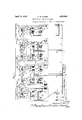
Referring now to Figure 1, l have shown at 1 the single phase cable constituting the conductor and the insulation for phase A. In a similar manner the cables for phases B and C are indicated at 1 and 1". Since each phase is the same as every other phase a description of one will suflice for the others. The cable terminates in an oil filled pothead 3, as shown at the left side of the drawings, and at 4 in the right side of the drawings. The cable proper comprises a lead sheath, a hollow conductor, and wrapped insulation between the conductor and the lead sheath, the central part of the cable providing a canal or passageway for oil which keeps the wrapping completely. saturated with oil to maintain the integrity of the insulation. Obviously the cable may be otherwise constructed without departing from my invention. The cable is made up in suitable lengths joined at manholes, as indicated at 5, 5 and the run of cable is sub-divided into sections by step joints as indicated at 6, 6, these stop joints being suitably constructed to sectionalize the oil channels of the cables. At one end or" each section, as for example, 88, standpipe connections communicating with the corresponding section of the cable are provided. These standpipe connections lead into reservoirs suitably designed and located at the adjacent ends of two sections. The pressure of oil in the cables may be main tained by a suitable gravity pressure head or pneumatic pressure head or other means for maintaining adequate pressure of oil to exclude air or moisture and insure free flow of the oil into the cable when the same cools. Likewise, the potheads 3 and at are provided with standpipe connections 77 for maintaining theend sections of cable iuli of oil at a predetermined pressure. The standpipes 7 and 8 lead upward to suitably located reservoirs l0l0 which are preferably collapsihis and expansible drums performing the function of both reservoirs and expansion.
for the respective sections of one phase will receive oil from the cable or discharge oil into the cable at substantially the same rate as those of another phase for changes in temperature due either to atmospheric conditions or to variations in load transmitted by the line, but if the group of tanks for one phase should show an expansion or contraction exceeding that of another phase; heed should be given at once to the condition of the cable, as such differential operation is indicative of an abnormal condition.
Suppose for illustration that the tanks have been adjusted so that the amount of oil in the tanks under the condition of minimum temperature in the winter time and without load is 25 gallons, and that the corresponding amount for the condition of maximum load on the cables is 50 gallons, then, if dependence should be placed upon a device which would act to give an indication only due to a predetermined minimum content of oil in the corresponding reservoir, the remaining oil under such conditions might escape or flow from the tanks before arrangement could be made to replenish the supply. If, however, the signaling scheme be arranged to send in an alarm when the tanks connected to one phase showed an oil content five gallons less than one of the other is lower, but the reserve measured in time for a given lea-k to emptythe tank is not greatly different.
I have provided means for determining the average condition of expansion or contraction by weighing the reservoirs or expansion tanks of each section for each phase and comparing the weight of one section with the weight of the expansion tanks of the corresponding section of another phase or other phases.
Each of the reservoirs 10-10 is suspended in a suitable mounting as, for example, on a yoke 11 connected to a lever 12 pivoted at 13 and counterbalanced by a spring 14. A counterbalancing weight might be employed instead. To the lever 12 I have connected an expansible element 15 by suitable connection 16, so that the expansible element 15 is actuated to change its displacement by movement of the lever 12. The expansible elements 15 are preferably small corrugated metal cylinders closed at their upper ends and connected at their lower ends to tubes 17, which tubes 17 in turn are connected to an oil filled manifold tube 18.
Both of the cylinders 15 for a. given section are manifolded to the pipe 18 and this pipe 18 is filled with a suitable fluid such,
for example, as oil of the same character as.
that employed in the cables.
The pipe 18 is preferably provided with an expansion tank 19 and with a filling and regulatin chamber 20. The chamber 20 is a collapsi le metal drum, which may be expanded or contracted for zero adjustment as by means of the adjusting screw 21.
This Zero adjustment is particularly valuable under the following circumstances. Assume that a leak develops in a section of the cable and some of the oil escapes from the cable and the reserve in the reservoirs connected to that section is thereby decreased. The signal means indicates the leakage and thereupon the workmen stop the leak by suitable repairs. Now it may be unnecessary to fill the reservoirs again because there may be sulficientmemaining to permit operation to continue for a time. The cost of replenishing the reservoirs is heavy because of the special processes and apparatus required even though only a small amount of oil is to be introduced. Hence, by suitable manipulation of the adjusting screw 21 and the reservoir 20, the displacement of oil in the transmitting tube 18 and connected parts may be compensated for the change of contents in the corresponding reservoirs 1010 of that particular section.
The pipe 18 is connected to gauge element 22 which has a movable member 23 like a steam gauge pointer, said movable element 23 being actuated as by means of a Bourdon tube or other element responsive to pressure or displacement and the movable element 23 plays between pairs of contacts 24 and 25, mounted on a block 26. The block 26 is movable on a guide 27 being held thereupon in any position by'frictional engagement.
The transmitting tube 18 and its connected parts form a closed system. The expansion tank 19 contains a body of air trapped in the top and, hence, displacement of liquid from the small bellows 1515 is permitted into the tank 19 with a corresponding rise of pressure in the system to which the gauge 22 is connected. Thus variations of displacement are translated into variations of pressure for moving the Bourdon tubes or like elements in the indicators 22. Obviously, if the active element had suflicient change of capacity as might be provided by a bellows element as shown in Figure 3 at 4040b and 400, the displacement of said bellows would be a measure of the displacement caused in the elements 1515 by variations of contents of reservoirs 10--10.
In Figure 1 I have shown the contacts 24 and so arranged as to close the circuit 28 for tripping the signal sending device 29 upon the occurrence of differences in pressure or displacement of the transmitting or manifold tube 18 for one phase from that of an adjacent phase. The contacts 24-25' of a corresponding indicator (not shown) have been shown as connected to give such differential indication between two phases. The third phase is not shown in this figure, but by reference to Figure 2 the complete arrangement will be seen.- As heretofore explained, I provide a differential indicating system where rise or fall of one sect-ion beyond the rise or fall of the corresponding sections gives the indication, as for example, by tripping the code sending device 29. The code sending device 29 is a non-interfering fire alarm box of known construction connected in a circuit 29' to one or more supervising stations where the code signal is received.
The diagram of Figure 1 shows two such signaling boxes for each tower, but it will be apparent that asingle box per tower may be arranged to be tripped or operated by the indicating devices of both adjacent sections. The code signal may be received at more than one receiving or supervising station.
In Figure 1 I have shown the instrument 22 for the A phase and indicated the contact springs 24 and 25 for another phase so that difierential operation is required between two gauges for two phases.
In practice the closing of circuit 28 is controlled by differential action between all three phases as will be explained more in detail in connection with Figures 2 and 3. Ohviously it is possible to put all the contacts 2425 for corresponding sections of each phase in parallel and allow a certain amount of play for each pointer 23 between such contact springs, but that does not give the close supervision that can be obtained by the differential action hereafter illustrated and described in detail.
Preferably, as shown in Figure 2, the gauges for corresponding sections of the three phases are connected to give an indication only if the pressure or displacement of one manifold tube 18 forone section is relatively low, or relatively high, with respect to another. The manner in which this is accomplished is by connecting the circuit of the responsive magnet 30 through the pairs of springs 24 and 25 of each of the instruments so that the contact pair 24 on one instrument must be closed and the contact pair 25 of another instrument must be closed at the same time in order to complete the circuit. To this end all of the outer spriings of the contact pair 25 are connected in parallel with the wire 31 and the other contacts of the contact pair 24 are connected in parallel to the wire 32 and the inner springs of both pairs of each instrument are connected in parallel to an intermediate wire 33. Thus assume that in the instrument 22 in phase A the pointer 23 swings counter-clockwise and closes the contact pair 25- and at the same time the pointer 23b of the instrument 22b swings clockwise and closes its contact pair 24?). It will be seen that a circuit is completed from the wire 31 to the contact pair 25 of the instrument 22 to the intermediate wire 33 to the inner contact of the pair 246 and to the outer spring of the pair 24?) and thence by wire 32 back through the magnet 30 to the source of current 34. The magnet 30 is thereupon energized, attracting its armature 35 and closing a circuit 36 through an indicating instrument 37 which in the present instance has been shown as a simple annunciator drop. Preferably the magnet 30 controls the tripping of a code sending box 29, as shown in Figure 1. @bviously, any form of signalling device which is desirable or suitable under the circumstances may be employed. In like manner if the pressure in any one of the three manifold pipes should drop and the pressure in the others advance the circuit will be closed giving the alarm.
I provide also limit contacts 66 and 67 arranged in the path of the movable block 26 to close the controlling circuit of the magnet 30, in case the pressure or displacement in the tube 18 of any particular phase drops to a predetermined limit. In other words, if the pressure or displacement in any of the tubes 18 should drop to a predetermined minimum an alarm is to be given since thiswould indicate leakage of the insulating 011. In a similar manner the contacts 67 are arranged individually to give an alarm in case of excessive pressure corresponding to a rise of temperature above apredetermined value in any particular phase.
Obviously, since the blocks 26 e connected together, only a single set of springs 66 or 67 is required.
It will be apparent that if the expansion of the three phases is substantially the same then the-movable members 23 will swing, for example, in a clockwise direction, and if this expansion is more than suflicient to close the contact springs 24 of each of the indicating devices the mounting blocks 26 on which they are supported will be shifted on a guide or track 27 to the extent required.
Obviously, the mounting blocks 26 of three instruments may be connected together as indicated at 68 so that continued advance of one of the indicator members 23 ahead of the others would serve first to close its corresponding contact pair 24, and next to bring the contact pair 25 of another instrument into engagement with the corresponding pointer 23 to close the circuit at such contact pair.
In Figures 3 and 4 I have indicated a modified form of the contact mechanism for performing the aforesaid functions.
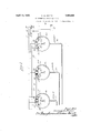
In this case the three tubes 18 for the three phases are-connected to expansible elements in the form of small metal bellows 4O mounted on a common base 41. Each of the small bellows has a rod such as 42 adapted to be moved by contraction and expansion of thecorresponding bellows. The upper ends of these rods are guided in a cross bar 43 extending between the vertical guides 44. A common base board 45 is guided on the vertical guides 44 as by means of pairs of rollers 46 and 47 and the base board 45 with the parts mounted thereupon is counterbalanced .so as to remain in any position on the guides is adapted to make electrical contact with the stationary contact screws 54 or 55, these contacts being adjustable in their mountings on the baseboard 451 A pair of limit contact springs 56 are mounted on the frame and are adapted to be engaged and closed by a pin 56' I on the baseboard 45 in case the baseboard 45 tor drop.
moves down far enough to exceed a predetermined position. The position of these contacts 56 is adjustable on the frame so that the said minimum position may be suitably predetermined. In like manner limit springs 57 may be employed to indicate when the baseboard 45 has moved up beyond a predetermined upper position. y
The movable contacts 53 of the three phases are all connected together, as indicated in Figure 4, and the lower contacts for the three phases are all connected together in multiple by a wire 59 ,and the upper contacts 54 are all connected together in multiple by wire 60. The magnet is included in circuit with its source of current 61 and wires 60 and 59. It controls in turn a circuit 36 through its armature for operating a signal device 37, shown in this case as a simple annuncia- To close the circuit of the magnet 30 requires that the wire 62 which connects the 65 contacts 53 should complete a circuit between The counterbalance for this base nections.
the wires 60 and 59. This may be done either by dropping one of the contacts 53 against its corresponding lower contact 55 and at the same time raising one of the contacts 53 into contact with the corresponding upper contact 54 or a circuit may be established by one of the contacts 53 rising or falling in advance of the other contacts or of another contact. This is true because continuous motion of one of the contacts 53 bringing it into engagement with the screws 54 or 55 causes the entire base board to be moved up or down as the case may be, thereby bringing one of the screws 54 or into engagement with another contact 53, whereby the circuit for the magnet 30 will be completed.
The limit contacts 5657 may be connected to the wires and 59, as shown in Figure 4, or they may be connected in a separate circuit to give a distinctive signal.
For zero adjustment in case of a loss of oil from one of the sections, the adjustable collar 52 on stem 42 may be shifted.
'It is obvious from the above description that one of the sets of contacts 54-55 or 546-555 or 540550 may be omitted by providing a between t e corresponding rod 42, 42?), or 420 and the base board 45 and making a cor-' responding change in the electric connections whereby a circuit is established between. the conductors 59 and 60 of Figure 4 when either one of the two remaining contact arms engages either its upper or its lower contact. This may be readily accomplished by connecting both the upper and the lower contacts that are mounted on the base board and engageable by the two remaining contact arms to the lower conductor 59 instead of to the lower and upper conductors 59 and 60 as shown in Figure 4. The two remaining contact arms may then be connected to the conductor 60. In like manner one of the sets of contacts such as the contacts 246' and 25b ma%be omitted from the modification shown in igure 2 by providing a permanent me-' chanical connection between the pointer 23b and the block 266. If this were done then the contacts 24 and 25 and the contacts 240 and 250 would be connected in arallel with the contacts 66 and 67 instead 0 in the manner shown.
ermanent mechanical connection I From the above it will be seen that my sys- I tem of indication provides means by which the overall increase or decrease of a particular group of reservoirs, as for example, for a single, phase, may be ascertained. The means for algebraically adding together the increases or decreases of the reservoirs for the sections of a given phase is in the present case the fluid containing pipe 18 and its con- It' will be obvious that other specific means for performing, this integration may be provided as, for example, resistances in an electric circuit may be employed. It
nesaees operation of said phase in absolute terms,
that is, the expansion or contraction of the oil in that particular phase without reference to what is going on in the other phases. Likewise, the position of the individual lever 12 indicates the condition of the contents of the particular associated reservoir 10.
The present application is particularly directed to the indicating means used, the electric system wherein the indicating means is used constituting the subject matter of my parent application of which this application is a division. I have however described, in more or less detail, the electric system and the manner whereby the differential indicating means is connected to the system in order to afford a clear understanding of the utility of my improved differential indicating means. l/Vhile the specification describes one manner of using my present invention it is to be understood that the differential indieating means herein shown is not limited in its use to a system such as has here been de scribed but is of a more general application.
It is to be understood that my present invention is not limited to the precise constructions herein set forth but is capable of various modifications within the spirit and scope of the appended claims. What I con sider new and desire to secure by Letters Patent is:
1. A difl'erential indicating means comprising two movable elements, means for moving each of the elements in accordance with respective variables to be differentiated, and movable means extending between the two elements and normally out of engagement with each of them and movable by either of them into operating engagement with the other..
2. A differential indicating means comprising two movable elements, means for moving each of the elements in accordance with respective variables to be differentiated, movable means extending between the two elements and normally out of engagement with each of them and movable by either of them into operating engagement with the other, and signalling means actuated responsive to the movement of the third element by one of the first elements into engagement with the other one of the two first mentioned elements.
3. A differential pressure indicating means comprising two movable elements, means for moving each of the elements in accordance with respective pressures to be differentiated, movable means extending between the first two elements and normally out of operating engagement with either of them and movable by either of them into engagement with the other, and signalling means actuated responsive to the movement of the last named movable means by one of the first elements into engagement with the other one of the two first mentioned elements.
4. In combination, a movable contact making member, a movable contact supporting structure including a set of contacts engaged by the contact making member responsive to a predetermined movement of the member, said structure being movable with the contact making member upon continued movement of said member, a second movable contact making member, and a second set of contacts mounted on the supporting structure and moved into engagement with the second contact making member upon movement of the supporting structure, and alarm means controlled by the joint action of both contact making members.
5. In combination, a movable contact making member, a movable contact supporting structure including a set of contacts in the path of movement of and engageable by the contact making member, said structure being movable with the contact making member upon continued movement of said member after it engages a contact on the structure, a second movable contact making member, and a second set of contacts mounted on the supporting structure in the path of movement of the second contact making member and moved into engagement therewith upon movement of the supporting structure, an electric circuit controlled by the joint action of both contact making members, and means for controlling said circuit responsive to the movement of the contact supporting structure beyond predetermined limits.
6. In combination a set of responsive devices each having a movable element and each having a movable contact supporting structure adapted to be engaged by the movable meter element and moved in either di rection thereby, and a connection between the movable contact supporting structures of the respective devices for moving them in unison whereby when one of the structures is moved by its element the other structure is thereby moved.
7. In combination a set of responsive devices each having a movable element and a movable contact supporting structure adapted to be engaged by the movable element and moved in either direction thereby; and a connection between the movable contact supporting structures of the respective devices for moving them in unison whereby when one of the structures is moved by its movable element the other structure is thereby moved, the contact supporting structure of each device including sets of contacts engageable with the opposite sides of their respective movable meter elements. v
8. In combination a plurality of expansible and contractible members, movable rods actuated by the. respective members, and means for detecting differences in the movement of the respective members, said means comprising an arm connected to the respective rods, a 10 single movable structure adapted to be engaged by either side of any arm and moved thereby, and indicating means actuated responsive to an engagement between the mova le structure and opposite sides of two different arms. 7
9. Differential indicating means comprising a lurality of responsive devices normally sub set to the same variable conditions and actuated alike responsive to like variations in the respective conditions, one of said devices including a member movable in response to said variations and movable over a prescribed path, a member actuated by another of said devices and movable over the actuated alike responsive to like variations in the respective conditions, one of said devices including a member movable in response to said variations and movable over a prescribed path, a member actuated byanother of said devices and movable over the same path, one
40 of said members including a contact making member, the other of said members including a cooperating contacting member embracing the contact making member but spaced therefrom and in the path of the movement there- }i-of, and limit switches controlled by at least one of said two first named devices.
, 11. In combination, a movable element movable over a prescribed path, a second movable element movable over the same path and including a pair of members spaced on opposite sides of the first element and in the path of movement of the first element, means including a-responsive device responsive to a predetermined type of variations for mov- 1,eus,ses
which the devices are responsive, whereby the relation between the contact and the contact making member is unaltered upon like actuation of the devices and is changed responsive to unlike actuation of said devices.
In witness whereof, I hereunto subscribe my name this 15th day of December, 1930. DENNEY W. ROPER.
SI ing the first element, and means including .a
responsive device responsive to the same type of variations for moving the second element.
12. In combination two pressure responsive devices, means including a contact mem- 00 ber movable by one of the devices responsive to pressure variations, means including a cooperatin contact makingmember movable by the ot er device responsive to pressure variations, said members being movable alike 65. responsive to like variations in pressure to izo
Priority Applications (7)
| Application Number | Priority Date | Filing Date | Title |
|---|---|---|---|
| US245025A US1853882A (en) | 1928-01-06 | 1928-01-06 | Differential method of indicating trouble on an oil filled cable |
| DE1930F0045230 DE581053C (en) | 1928-01-06 | 1930-04-12 | Method for determining the location of leaks in sewers that are arranged in high-voltage cables or cable systems for receiving a gaseous pressure medium |
| DE1930F0096430 DE606845C (en) | 1928-01-06 | 1930-08-15 | Method for determining the location of leaks in sewers which are arranged in high-voltage cables or cable systems for receiving a gaseous pressure medium |
| US503519A US1853883A (en) | 1928-01-06 | 1930-12-19 | Differential indicating means |
| GB1062/31A GB361183A (en) | 1928-01-06 | 1931-01-12 | An improved method of localizing leakages in ducts provided in high-voltage cables for the reception of a fluid under pressure |
| BE379804D BE379804A (en) | 1928-01-06 | 1931-05-19 | |
| FR717570D FR717570A (en) | 1928-01-06 | 1931-05-23 | Method for locating a fault in air-insulated telephone cables |
Applications Claiming Priority (4)
| Application Number | Priority Date | Filing Date | Title |
|---|---|---|---|
| US245025A US1853882A (en) | 1928-01-06 | 1928-01-06 | Differential method of indicating trouble on an oil filled cable |
| DE1930F0045230 DE581053C (en) | 1928-01-06 | 1930-04-12 | Method for determining the location of leaks in sewers that are arranged in high-voltage cables or cable systems for receiving a gaseous pressure medium |
| DE1930F0096430 DE606845C (en) | 1928-01-06 | 1930-08-15 | Method for determining the location of leaks in sewers which are arranged in high-voltage cables or cable systems for receiving a gaseous pressure medium |
| US503519A US1853883A (en) | 1928-01-06 | 1930-12-19 | Differential indicating means |
Publications (1)
| Publication Number | Publication Date |
|---|---|
| US1853883A true US1853883A (en) | 1932-04-12 |
Family
ID=27194223
Family Applications (2)
| Application Number | Title | Priority Date | Filing Date |
|---|---|---|---|
| US245025A Expired - Lifetime US1853882A (en) | 1928-01-06 | 1928-01-06 | Differential method of indicating trouble on an oil filled cable |
| US503519A Expired - Lifetime US1853883A (en) | 1928-01-06 | 1930-12-19 | Differential indicating means |
Family Applications Before (1)
| Application Number | Title | Priority Date | Filing Date |
|---|---|---|---|
| US245025A Expired - Lifetime US1853882A (en) | 1928-01-06 | 1928-01-06 | Differential method of indicating trouble on an oil filled cable |
Country Status (5)
| Country | Link |
|---|---|
| US (2) | US1853882A (en) |
| BE (1) | BE379804A (en) |
| DE (2) | DE581053C (en) |
| FR (1) | FR717570A (en) |
| GB (1) | GB361183A (en) |
Cited By (1)
| Publication number | Priority date | Publication date | Assignee | Title |
|---|---|---|---|---|
| US4189707A (en) * | 1978-06-05 | 1980-02-19 | Ermert Ronald A | Engine air intake warning system |
Families Citing this family (5)
| Publication number | Priority date | Publication date | Assignee | Title |
|---|---|---|---|---|
| US2433505A (en) * | 1944-09-21 | 1947-12-30 | Okonite Callender Cable Co Inc | Means for locating electrical faults in electric cable systems |
| US2788658A (en) * | 1951-12-01 | 1957-04-16 | Ericsson Telefon Ab L M | Apparatus for indicating and localizing leaks in gas-pressure protected cables |
| BE544077A (en) * | 1955-01-24 | 1956-01-14 | ||
| GB2061526B (en) * | 1979-10-18 | 1983-10-19 | Electricity Council | Locating a leak in an oil filled cable |
| EP2913790A1 (en) | 2008-09-09 | 2015-09-02 | Truecar Inc. | System and method for calculating and displaying price distributions based on analysis of transactions |
-
1928
- 1928-01-06 US US245025A patent/US1853882A/en not_active Expired - Lifetime
-
1930
- 1930-04-12 DE DE1930F0045230 patent/DE581053C/en not_active Expired
- 1930-08-15 DE DE1930F0096430 patent/DE606845C/en not_active Expired
- 1930-12-19 US US503519A patent/US1853883A/en not_active Expired - Lifetime
-
1931
- 1931-01-12 GB GB1062/31A patent/GB361183A/en not_active Expired
- 1931-05-19 BE BE379804D patent/BE379804A/xx unknown
- 1931-05-23 FR FR717570D patent/FR717570A/en not_active Expired
Cited By (1)
| Publication number | Priority date | Publication date | Assignee | Title |
|---|---|---|---|---|
| US4189707A (en) * | 1978-06-05 | 1980-02-19 | Ermert Ronald A | Engine air intake warning system |
Also Published As
| Publication number | Publication date |
|---|---|
| BE379804A (en) | 1931-06-30 |
| DE606845C (en) | 1934-12-12 |
| GB361183A (en) | 1931-11-19 |
| DE581053C (en) | 1933-07-20 |
| US1853882A (en) | 1932-04-12 |
| FR717570A (en) | 1932-01-09 |
Similar Documents
| Publication | Publication Date | Title |
|---|---|---|
| US1853883A (en) | Differential indicating means | |
| US2261742A (en) | Electric cable | |
| US2004769A (en) | Means for and method of detecting and ascertaining the region of oil leaks in cable systems | |
| NO119583B (en) | ||
| US1875732A (en) | Sealing device for use with electric cables and other apparatus | |
| US2432568A (en) | Gas filled cable system | |
| US2225653A (en) | Compensation for variations in phase change | |
| US2326557A (en) | Electric cable | |
| US3336584A (en) | Tell-tale system for jacketed piping systems | |
| US2803692A (en) | Fluid | |
| US3466642A (en) | Method and device for automatic leakage detection in liquid-pressure insulated power cables | |
| Hochstadter et al. | THE PRESSURE CABLE. An Advance in the Construction of High Voltage Cable Installations | |
| US20230009953A1 (en) | System voltage calibration | |
| Brazier et al. | An assessment of the impregnated pressure cable | |
| Brazier | Joints, sealing ends and accessories for pressure cable | |
| John | Bushing insulators for outdoor transformers | |
| US1933347A (en) | Underground oil-filled cable | |
| US2092559A (en) | Signal means for fluid filled cables | |
| Farnham et al. | Design, manufacture, and installation of 120-Kv oil-filled cables in Canada | |
| US1719067A (en) | martin | |
| US2219262A (en) | System for detecting and locating defects in cable sheaths | |
| US1904226A (en) | Cable maintenance apparatus | |
| US3075380A (en) | Means for detecting and localizing oil leakages in electric cables | |
| Torchio | 132,000-Volt, Single-Conductor, Lead Covered Cable Introduction, Economics and Commercial Demand | |
| US1911350A (en) | Indicating device |