US1853874A - Parachute mounting for airplanes - Google Patents
Parachute mounting for airplanes Download PDFInfo
- Publication number
- US1853874A US1853874A US498028A US49802830A US1853874A US 1853874 A US1853874 A US 1853874A US 498028 A US498028 A US 498028A US 49802830 A US49802830 A US 49802830A US 1853874 A US1853874 A US 1853874A
- Authority
- US
- United States
- Prior art keywords
- casing
- parachute
- releasing
- airplane
- plane
- Prior art date
- Legal status (The legal status is an assumption and is not a legal conclusion. Google has not performed a legal analysis and makes no representation as to the accuracy of the status listed.)
- Expired - Lifetime
Links
- 230000000994 depressogenic effect Effects 0.000 description 2
- 101100161290 Mus musculus Nt5c1b gene Proteins 0.000 description 1
- 238000010276 construction Methods 0.000 description 1
- 230000000881 depressing effect Effects 0.000 description 1
- 230000000717 retained effect Effects 0.000 description 1
Images
Classifications
-
- B—PERFORMING OPERATIONS; TRANSPORTING
- B64—AIRCRAFT; AVIATION; COSMONAUTICS
- B64D—EQUIPMENT FOR FITTING IN OR TO AIRCRAFT; FLIGHT SUITS; PARACHUTES; ARRANGEMENT OR MOUNTING OF POWER PLANTS OR PROPULSION TRANSMISSIONS IN AIRCRAFT
- B64D25/00—Emergency apparatus or devices, not otherwise provided for
- B64D25/08—Ejecting or escaping means
- B64D25/12—Ejectable capsules
Definitions
- My invention relates to parachutes and y I am aware that it is not n ew to provide 1 5 a parachute capable of supporting an airplane, but an object of my invention is to provide an improved means of attachment of the parachute to the plane.
- Another object is to provide a parachute isiupport which will hold the plane Von an even eel. l
- Another object of the invention is to rovide a. storage box or casing in the airp ane to hold the parachute when not in use and also to provide means for positively ejecting the arachute from the casing whenever de sire so that the parachute will catch the wind and be inflated immediately.
- Another object of the invention is to provide means controlled from the pilots seat for releasing and ejecting the parachute.
- Another object of the invention is to provide mea-ns which will prevent release .of the box from the airplane unless the parachute has first been ejected from the box.
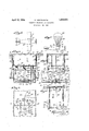
- Figure 1 is a plan view of an airplaneiitted with my improved parachute
- Fig. 2 is a side elevation showing an air' plane supported by the parachute
- FIG. 3 1s a fragmental view in section l taken on the line 3 3 of Fig. 1;
- Fig. 4 is afragmental side view of the parachute casing attached to the fuselage of theairplane
- Fig. 5 1s a view in section taken on the line 5-5 of Fig. 3;
- Fig. 6 is a view in section taken onthe line 6-6 of Fig. 4. f
- the reference numeral 10 to indicate the fuselage of a biplane, the upper wing ofwhich is indicated by the numeral 11 and the lower wing by the'numeral 12.
- the wings are conn'ectedby thensual struts 13.
- an opening l14 lthrough which may be passed a box or casing adapted to hold the parachute.
- This casing comprises a bottom wall 15 which rests on the fuselage 10, and side walls 16.
- the top of the casing is closed by a pair of doors 17 hinged thereto as indicated'at 18 70' and lying substantially Hush with theupper surface of the wing 11.
- the doors are arranged tolap one over the other along their line of juncture so that both of the doors may be held shut by locking the overlapping door in closed position.
- the casing is'held to the fuselage by means of latches 19 which. are adapted to engage vlugs 20 projecting from the bottom wall.
- bearings 30 for a pair of arms 31 which normally areapassed over the oke 23 and retained at their outer ends b a ail 32 pivota-lly mounted on the floor o thefuselage.
- the bail is l formed with a pedal extension 33 located adjacent the pilots seat so that the pilot may depress the pedal to withdraw the bail from ends of the arms 31 and permit the springs 24 to drive the head plate 22 upward.
- the doors 17 are held in closed position by a vertical rod 34 which at its upper end hooks over one of the doors 17 and at its lower end hooks under one of the arms 31.
- the doors will be released and the springs 24 can then throw the parachute out of the box, inging the doors open so that they will rest uponthe upper wing.
- the arachute is ejected, it is thrown up with suihient force to carry it well above the wing so that it will catch the wind and will quickly become inflated.
- the airplane will then be supported by the parachute.
- the parachute is not directly attached to the airplane, but is secured to the casing, which in turn isfastened to the fuselage by the latches 19. Whenever it is desired to detach the parachute from the airplane this can be done by merely spreading the latches 19.
- latches 19 There are four latches 19 arranged in two opposed pairs. Each pair is connected by a system of toggle links 35 and 36 to a vertical bar 37 in such manner that when the bar is raised the latches will be spread apart to release their hold on the lugs 20.
- the vertical bars are pressedl upward by springs 38, but are normally locked against the lift of said springs.
- the opposite bars 37 are yoked together by means of a connecting rod 39 which is bent downward, intermediate its ends so as to pass under the-yoke 2.3. Thus, as long as the yoke is held in depressed position the latches 19 cannot be released.
- An auxiliary means for holding the bars 37 in depressed position consists of a lever 40, one arm of which bears down upon the connectingrod 39, while the other is supported by a locking lever 41.
- the locking lever is fulcrumed to swing in a plane transverse to that of the lever 40 and is formed with a vertical arm having aV notch 42 in which the adjacent end of the lever 40 is seated.
- the springs 24 provide the pedal 33, thereby withdrawing the 'l' a resilient support for the head plate 22 so as to cushion any jars that may occur on landlt will be observed that the casing for the parachute is located above the fuselage so that a passage thereunder is provided between the pilots compartment and the pas-- sengers cabin.
- the releasing mechanism located under the casing does not materially obstruct the passage.
Landscapes
- Business, Economics & Management (AREA)
- Emergency Management (AREA)
- Engineering & Computer Science (AREA)
- Aviation & Aerospace Engineering (AREA)
- Toys (AREA)
Description
April 12, 1932. R. MoNTELEoNE 1,853,874
PARACHUTE MOUNTING FOR `AIPLANES Filed NOV. 25, 1930 l v W l i zo 5 fg Il?! INVENTOR' y Patented Api. 12, 1932 UNITED s'lxxrlezs Rocco noNTEEEoNE, or JERSEY ci'rY, NEW JERSEY rmcnurn uoUNrme .ron ararmNEs Application led November 25, 1930. Serial No. 496,028.
My invention relates to parachutes and y I am aware that it is not n ew to provide 1 5 a parachute capable of supporting an airplane, but an object of my invention is to provide an improved means of attachment of the parachute to the plane.
Another object is to provide a parachute isiupport which will hold the plane Von an even eel. l
Another object of the invention is to rovide a. storage box or casing in the airp ane to hold the parachute when not in use and also to provide means for positively ejecting the arachute from the casing whenever de sire so that the parachute will catch the wind and be inflated immediately.
Another object of the invention is to provide means controlled from the pilots seat for releasing and ejecting the parachute.
In the case of certain accidents, particularly where the airplane takes fire, it is. desirable for the passengers to leave the airplane and for this reason `I have provided a storage box for the parachute and to which the parachute is permanently attached, said box being detachable from the airplane so as to provide a means of-escape for the passengers. A11 advantage of this arrangement lis that it rovides a convenient means of detaching t e parachute from the airplane should it be released and ejected from the box accidentally.
Another object of the invention is to provide mea-ns which will prevent release .of the box from the airplane unless the parachute has first been ejected from the box.
lWith these objects in view and others which will appear hereinafter, I shall now describe a preferred embodiment of my invention and thereafter shall point out the novelty and sco e of the invention in the claims.
n the accompanying drawings; l
Figure 1 is a plan view of an airplaneiitted with my improved parachute;
Fig. 2 is a side elevation showing an air' plane supported by the parachute;
- Fig. 3 1s a fragmental view in section l taken on the line 3 3 of Fig. 1;
Fig. 4 is afragmental side view of the parachute casing attached to the fuselage of theairplane;
Fig. 5 1s a view in section taken on the line 5-5 of Fig. 3; and
Fig. 6 is a view in section taken onthe line 6-6 of Fig. 4. f
In the drawings, I have used the reference numeral 10 to indicate the fuselage of a biplane, the upper wing ofwhich is indicated by the numeral 11 and the lower wing by the'numeral 12. The wings are conn'ectedby thensual struts 13. At the center ofthe upper wing is provided an opening l14 lthrough which may be passed a box or casing adapted to hold the parachute. This casing comprises a bottom wall 15 which rests on the fuselage 10, and side walls 16. The top of the casing is closed by a pair of doors 17 hinged thereto as indicated'at 18 70' and lying substantially Hush with theupper surface of the wing 11. The doors are arranged tolap one over the other along their line of juncture so that both of the doors may be held shut by locking the overlapping door in closed position. The casing is'held to the fuselage by means of latches 19 which. are adapted to engage vlugs 20 projecting from the bottom wall.
Passing through the bottom wall 15 are 80 three vertical rods21 which are connected at their upper ends by a head plate 22 fitted to slide in the casing. At their lower ends the rods are connected by a yoke 23. Springs 24 on the rods and bearing between the head plate and the. b ottom wall 15, tend to force the plate upward. In the space above the head plate when in the lowered position shown in Fig. 3, is a folded parachute 25'. This parachute is connected by cords or ropes 26 to the casing. The ropes pass through grommets 27 inthe side wallsv 16 to the exterior of thebox and are led down to the bottorn of the box where they are attached to bolts or other fastenings 27.
Fixed to the floor of the fuselage are bearings 30 for a pair of arms 31 which normally areapassed over the oke 23 and retained at their outer ends b a ail 32 pivota-lly mounted on the floor o thefuselage. The bail is l formed with a pedal extension 33 located adjacent the pilots seat so that the pilot may depress the pedal to withdraw the bail from ends of the arms 31 and permit the springs 24 to drive the head plate 22 upward.
The doors 17 are held in closed position by a vertical rod 34 which at its upper end hooks over one of the doors 17 and at its lower end hooks under one of the arms 31. Thus, on releasing the arms 31 the doors will be released and the springs 24 can then throw the parachute out of the box, inging the doors open so that they will rest uponthe upper wing. When the arachute is ejected, it is thrown up with suihient force to carry it well above the wing so that it will catch the wind and will quickly become inflated. The airplane will then be supported by the parachute.
|The parachute is not directly attached to the airplane, but is secured to the casing, which in turn isfastened to the fuselage by the latches 19. Whenever it is desired to detach the parachute from the airplane this can be done by merely spreading the latches 19.
There are four latches 19 arranged in two opposed pairs. Each pair is connected by a system of toggle links 35 and 36 to a vertical bar 37 in such manner that when the bar is raised the latches will be spread apart to release their hold on the lugs 20. The vertical bars are pressedl upward by springs 38, but are normally locked against the lift of said springs. The opposite bars 37 are yoked together by means of a connecting rod 39 which is bent downward, intermediate its ends so as to pass under the-yoke 2.3. Thus, as long as the yoke is held in depressed position the latches 19 cannot be released.
An auxiliary means for holding the bars 37 in depressed position consists of a lever 40, one arm of which bears down upon the connectingrod 39, while the other is supported by a locking lever 41. The locking lever is fulcrumed to swing in a plane transverse to that of the lever 40 and is formed with a vertical arm having aV notch 42 in which the adjacent end of the lever 40 is seated. The
The operation of the apparatus vis as -rollows: Wheneveritis desiredto release the parachute from its casing the pilot steps u on 32 from the arms 31, and permitting the springs 24 to thrust the head plate 22 upward. At the same time the rod 34 is released, so that the doors 17 are flung open and the parachute is shot out of its casing. The Wind catching the parachute will immediately inate it and the plane will then be supported as shown in Fig. 2. The location of the parachute casing is such as to hold the plane on an even keel fore-and-aft, as well as laterally.
Tf by any chance the parachute should be ejected accidentally it togetherwith the casing may be detached from the plane by lifting the arm 43 of the locking lever. This releases the bars 37 permitting them. to rise, under impulse of springs 38, and spread open the latches 19. ln case of lire or whenever it is desired to abandon the airplane, the parachute is irstejected from its casing by depressing the pedal 33, after which the passengers and pilot climb up upon the top of casing sitting or standing on the head plate 22 and holdin fast to the ropes 26. Then a pull on the 'ca le 44 will cause the latches 19 to release the casing. The springs 24 provide the pedal 33, thereby withdrawing the 'l' a resilient support for the head plate 22 so as to cushion any jars that may occur on landlt will be observed that the casing for the parachute is located above the fuselage so that a passage thereunder is provided between the pilots compartment and the pas-- sengers cabin. The releasing mechanism located under the casing does not materially obstruct the passage.
While I have described a preferred embodiment of my invention it will be understood that this is to be taken as illustrative and not limitative, and that I reserve the right to make such changes in form, construction and arrangement of parts as fall within the spirit and scope of the following claims.
1. In combination with an airplane, a casing mounted on and secured to the usela e of the airplane, a parachute secured to t e casing and normally stowed therein, rods vertically slidable through the bottom of the casing, a plunger head carried by the rods and slidable in the casing, springs on the rods urging the plun er upward, a yoke secured to the lower en s of the rods, means acting upon the (yoke for holding the plunger head in lowere position, and a lever adjacent the pilotsseat 1n thefuselage for releasing said means. v v
2. In combination with an air lane, a cas ing mounted on the fuselage oft e airplane, a parachute lsecured to the casing and normall V stowed therein, rods vertically -slidable t rough the bottom of the casing, a plunger aty los
head carried by the rods, springs urging laol head in lowered position, a lever adjacent the l pilots seat in the fuselage for releasing the retaining means, means for attaching the casing to the fuselage, and releasing means for releasing the attaching means, the last named means being inoperative until theplunger has `been released.
3. In combination with a bi-pl'ane having an opening in the upper wing thereof, a casing slidable through said opening, a parachute normally stowed in the casing, spring pressed means for ejecting the parachute from the casing, means for releasing the spring pressed means, whereby the parachute will be forcibly ejected from the casing, latching means for holding the casing to the biplane, and means for releasing said latching means.
4. In combination with a bi-plane having an opening in the upper wing thereof, a casing slidable through said opening, a parachute normally stowed in the casing, means for releasing the spring pressed means, r
whereby the parachute will be forcibly ejected from the casing, latch means for holding the casing to the bi-plane, and means operable from the top of the casing for releasing the latch means.
5. In combination with a bi-plane having an opening in the u per wing thereof, a casing slidable throug said opening, a parachute normally stowed in the casing, means for releasing the spring pressed means wherebythe parachute will be forcibly ejected from. thecasing, latch means for holding the casing to the bi-plane, means operable from the top of the casing for releasing the latch means,
and means for preventing release of the casspecification.
'ing from the bi-plane until after the para-` chute has been ejected from the casing.
In testimony whereof, I have signed this Rocco MoNTELEoNE.
Priority Applications (1)
| Application Number | Priority Date | Filing Date | Title |
|---|---|---|---|
| US498028A US1853874A (en) | 1930-11-25 | 1930-11-25 | Parachute mounting for airplanes |
Applications Claiming Priority (1)
| Application Number | Priority Date | Filing Date | Title |
|---|---|---|---|
| US498028A US1853874A (en) | 1930-11-25 | 1930-11-25 | Parachute mounting for airplanes |
Publications (1)
| Publication Number | Publication Date |
|---|---|
| US1853874A true US1853874A (en) | 1932-04-12 |
Family
ID=23979322
Family Applications (1)
| Application Number | Title | Priority Date | Filing Date |
|---|---|---|---|
| US498028A Expired - Lifetime US1853874A (en) | 1930-11-25 | 1930-11-25 | Parachute mounting for airplanes |
Country Status (1)
| Country | Link |
|---|---|
| US (1) | US1853874A (en) |
Cited By (4)
| Publication number | Priority date | Publication date | Assignee | Title |
|---|---|---|---|---|
| US2712855A (en) * | 1952-08-28 | 1955-07-12 | Lightbourn Salvador | Aircraft lift-propulsion propeller system |
| US3833192A (en) * | 1972-11-13 | 1974-09-03 | G Spector | Safety device for airplanes land safety |
| US4033528A (en) * | 1976-07-01 | 1977-07-05 | Diggs Richard E | Aircraft parachute system |
| US5673875A (en) * | 1995-01-30 | 1997-10-07 | Martin; Joseph R. | Stabilizing inflight parachute system |
-
1930
- 1930-11-25 US US498028A patent/US1853874A/en not_active Expired - Lifetime
Cited By (4)
| Publication number | Priority date | Publication date | Assignee | Title |
|---|---|---|---|---|
| US2712855A (en) * | 1952-08-28 | 1955-07-12 | Lightbourn Salvador | Aircraft lift-propulsion propeller system |
| US3833192A (en) * | 1972-11-13 | 1974-09-03 | G Spector | Safety device for airplanes land safety |
| US4033528A (en) * | 1976-07-01 | 1977-07-05 | Diggs Richard E | Aircraft parachute system |
| US5673875A (en) * | 1995-01-30 | 1997-10-07 | Martin; Joseph R. | Stabilizing inflight parachute system |
Similar Documents
| Publication | Publication Date | Title |
|---|---|---|
| US2352721A (en) | Parachute and automatic opening device therefor | |
| US1853874A (en) | Parachute mounting for airplanes | |
| US2684219A (en) | Aircraft with detachable cabin | |
| US1731531A (en) | Aircraft | |
| US2389160A (en) | Airplane troop launching means | |
| US2077910A (en) | Flying machine | |
| US2392448A (en) | Parachute | |
| US1798137A (en) | Load-discharging means for airplanes | |
| US2115932A (en) | Safety appliance for airplanes | |
| US1337336A (en) | Life-saving device for aeroplanes | |
| US1677638A (en) | Safety device for airplanes | |
| US1646586A (en) | Aeroplane safety device | |
| US2693923A (en) | Airplane lifesaver device | |
| US1874392A (en) | Parachute | |
| US1970812A (en) | Aircraft | |
| US1465835A (en) | Parachute for aerial vessels | |
| US1814325A (en) | Safety device for aeroplanes | |
| US2335822A (en) | Airplane | |
| US1862989A (en) | Safety appliance for aircraft | |
| US1804156A (en) | Safety device for aeroplanes | |
| US1885570A (en) | Aircraft | |
| US1509032A (en) | Parachute attachment for airships | |
| US1716597A (en) | Airship | |
| GB474862A (en) | Safety device for aircraft | |
| US2066810A (en) | Aircraft |