US1853870A - Shutter control device - Google Patents
Shutter control device Download PDFInfo
- Publication number
- US1853870A US1853870A US495890A US49589030A US1853870A US 1853870 A US1853870 A US 1853870A US 495890 A US495890 A US 495890A US 49589030 A US49589030 A US 49589030A US 1853870 A US1853870 A US 1853870A
- Authority
- US
- United States
- Prior art keywords
- engine
- shutters
- thermostat
- bellows
- expansible
- Prior art date
- Legal status (The legal status is an assumption and is not a legal conclusion. Google has not performed a legal analysis and makes no representation as to the accuracy of the status listed.)
- Expired - Lifetime
Links
- 239000007788 liquid Substances 0.000 description 5
- XLYOFNOQVPJJNP-UHFFFAOYSA-N water Substances O XLYOFNOQVPJJNP-UHFFFAOYSA-N 0.000 description 5
- 238000003466 welding Methods 0.000 description 3
- 230000006835 compression Effects 0.000 description 2
- 238000007906 compression Methods 0.000 description 2
- 239000000110 cooling liquid Substances 0.000 description 2
- 230000007423 decrease Effects 0.000 description 2
- 235000010627 Phaseolus vulgaris Nutrition 0.000 description 1
- 244000046052 Phaseolus vulgaris Species 0.000 description 1
- 230000008602 contraction Effects 0.000 description 1
- 238000001816 cooling Methods 0.000 description 1
- 230000000694 effects Effects 0.000 description 1
Images
Classifications
-
- F—MECHANICAL ENGINEERING; LIGHTING; HEATING; WEAPONS; BLASTING
- F01—MACHINES OR ENGINES IN GENERAL; ENGINE PLANTS IN GENERAL; STEAM ENGINES
- F01P—COOLING OF MACHINES OR ENGINES IN GENERAL; COOLING OF INTERNAL-COMBUSTION ENGINES
- F01P7/00—Controlling of coolant flow
- F01P7/02—Controlling of coolant flow the coolant being cooling-air
- F01P7/10—Controlling of coolant flow the coolant being cooling-air by throttling amount of air flowing through liquid-to-air heat exchangers
- F01P7/12—Controlling of coolant flow the coolant being cooling-air by throttling amount of air flowing through liquid-to-air heat exchangers by thermostatic control
Definitions
- Myinvention relates to improvements in engine shutter apparatusand more particu-q larly to an improved automatic control means 1 .therefor. m f In automatic radiatorlshuttersfor auto- V motive vehiclesit has.
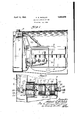
- ' Fig. 1 is a partly tion of anautomati've engine and radiatorillustrate'd withthe shutter operating device. invention attached thereto, parts being 'of my h broken away to show certain .parts more; 'clearlygand- Fig. 2 is an-enlarged cross sectional plan view of the operating parts'of the automatic control of my invention.
- FIG. 1 is shown an automotive engine 3 having anoil pump 1
- a radiator 5 comprising the is shown mounted in the conventional manner in mounted on n spot-welding,
- Such shutter apparatus may be of I suitable means; A 2, has a plurality of openings 9 therein, allowmg the water which circulates in thecooling ofmy invention to provide means for closing the shuttersof an r to. form a shoulder,
- a radiator shutter '6 of the'type ' which or in some other suitable manner.
- well-known designs a I have "illustrated athe rmostat shell 8 tank of the radiator byweldingfor'some other This shell, as shown-in Fig;
- corrugated metallic diaphragm 10 is mountedwithv in the shell 8 between ashoulder ll fo rme'd n one end thereof and aflange12'of a cupshaped housing member 13 by means of "welding or in -some other suitable manner which will provide a leak-proof connection.
- the arm 22 is g 24, one corner of which is triangular arm pivotallymounted on the stud 25.- As shown ini Fig. 2, the other corner of the triangular comprises a plurality of shutters ome'dtoa common operating bar 7, whereby they are all opened andclosedsimultaneously, e the radiator by bolts; rivet-' mounted in a leak-proof mannerin the Water so An e'xpansiblethermostat 15 'of well-known type screw-threaded lows 10 surrounding the aperture therein,
- An expansible bellows is disposed within the other end of the shell 8 and has a screw threaded inlet bushing 31 formed thereon by which the bellows is mounted in a plate 33.
- the plate 33 is: secured to the end of the shell 8 and to the external wall of the water tank ofthe radiatorby means of welding or in some other suitable manner.
- An oil supply line 35 connected with the pressure oiling system of theengine at the oil pump, or some other desirable connecting pointin the oil supply line, is suitably connected with the inlet 31 of the bellows 30 by means of the bushing 36 or other leakproof connecting means to supply oil to the bellows.
- a stud 37 is formed on one side of *the expansible bellows 30 and has a set screw 38 screw threaded therein which is in align ment with a stud 39 formed at one end of the thermostat 1'5 and adapted to contact "therewith when the bellows is expanded.
- the expansible bellows 30' is in direct communication with the oil pressure system of p the automotive engine and is adapted'to be filled with oil from the engine and expanded thereby when the engine is operating.
- bellows are designed to expand at the normal operating oil pressures of the engine.
- thermostat 15 may expand without moving the arm 16 when the bellows 30 are in a contracted posi- 39 seats against the adjustableset screw 38 of the bellows 30.
- thermostat While the engine is operating and the engine temperature is of sufi'iciently high degree to expand the thermostat 15 and open the shutters, the thermostat will be firmly seated against the adjustable set screw 38 of the bellows 30.
- the engine When the engine is shut off changes in the oil-pressure '01"- the engineto render the thermostat means eiiective when the engine is operating and ineffective when the engine is stopped.
- thermostat means responsive to changes in engine temperature to open and close the shutters, and automatic means responsive .to
- a l plurality of shutters In an automotive engine radiator .shu-t ter apparatus, a l plurality of shutters, a thermostat to expand and open the shutters upon increases in engine temperature, a spring to cause the shutters to close 'upon contraction of the thermostat when the engine temperature "decreases, an oil pump in the engine,-an'd means responsive to the oil pressure created by said pump to render the thermostat ineffective when the engine is stopped and allow the spring to close the shutters regardless of the temperature ⁇ of the engine.
- a spring for urging said thenmostat in a direction to close said shutters, and an expansible bellows expanded by the oil pressure developed by the engine to resist movement of the thermostat in a shutter closing direction by the spring when the'engine is running and adapted to collapse and allow such movement when the engine is stopped.
- a shutter control unit comprising a thermostat housing disposed within the water tank of the radiator, an expansible thermostat therein, a shutter operating shaft connected with said thermostat and reciprocable therewith to open the shutters when the thermostat expands and the shaft is moved outwardly, a spring to urge said shaft and attached thermostat inwardly to close theshutters when the thermostat contracts, and
- an expansible bellows operated by the oil pressure developed by the oil pump of the engine disposed within said housing in alignoperating to provide such abutment when and I a only when the engine is operating.
- shutters for controlling the flow of cooling air to an engine
- a thermostat responsive to engine, adapted when held against expansion in one direction toexpand in the other direction to effect the opening of the shutters, and means for utilizing the oil pressure of the engine for preventing expansion of the shutters in said first-mentioned direction when and only when the engine is in operation.
- a chamber adapted to receive liquid from the cooling liquid circulating system of the engine a'first expansible vessel in said chamber, said first expansible vessel expanding and contracting in response to changes in the temperatureof the liquid, a second expansible vessel in said chamber, said second expansible vessel aifording an abutment for the first. expansible vessel, means for causing said second expansible vessel to be expanded when the engine is in operation, shutters, and means alfording an operating connection between the shutters and the first expansible vessel.
- a second expansible vessel in said chamber said'second expansible vessel afi'ording an abutment for the first expansible vessel, means for causing said second expansible vessel to be expanded when the engine is in operation, shutters, and means affording an operating connection between the shutters and thefirst expansible vessel, said last mentioned means comprising a flexible diaphragm constituting a closure for the aforesaid chamber and an operating rod exhaving liquid tight connection with said diaphragm.
- a chamber adapted to receive liquid from the cooling liquid circulating system of the engine, a first expansible vessel in said chamber, said
Landscapes
- Engineering & Computer Science (AREA)
- Chemical & Material Sciences (AREA)
- Combustion & Propulsion (AREA)
- Mechanical Engineering (AREA)
- General Engineering & Computer Science (AREA)
- Temperature-Responsive Valves (AREA)
Description
April 12, 1932. A. G. MCCALEB 1,853,370
SHUTTER CONTROL DEVICE Filed Nov. 15, 1930 r /39 W 67 g Patented Apr. 12, 1932 i 1 UNITED if STAT S," PATENT oFFIcE.
ALBERT G.
MCCALEB, or EVANSTON, irninors 'essren'on ro PINES WINTERFRONT coM- rANY, on CHICAGO, ILLINOIS, n CORPORATION or DELAWARE "SHUTTER ooivrnonnnvrcn Application filed November 15, 1930. Serial No. 1495,890.
Myinvention relates to improvements in engine shutter apparatusand more particu-q larly to an improved automatic control means 1 .therefor. m f In automatic radiatorlshuttersfor auto- V motive vehiclesit has.
been. ;;found desirable to cause the s'huttersto assume a closed posi tion whenever thexengine-is shut ofi,- thus 1 maintaining the'heat within-the hooded en 1 -10 gine compartment to provide easier' re-start ing of the engine during cold weather, and
resulting in numerous other advantages.
.i It-is an objectlofmy invention to provide an improved means for;automatically caus-. '15 ing the shutters of an automotive engine to 2 close when the engine stops.
It is another object automotive englne when the: engine has a responsive to. 01].
stopped, which meansiis pressure created Lby.;the engine itself.
It is still another j object of my invention to provide oil pressure control meansfor oooperating with a thermostatic operating fme'ans ofa radiator Y shutter: apparatus-to.
panying drawings, in which:
' Fig. 1 is a partly tion of anautomati've engine and radiatorillustrate'd withthe shutter operating device. invention attached thereto, parts being 'of my h broken away to show certain .parts more; 'clearlygand- Fig. 2 is an-enlarged cross sectional plan view of the operating parts'of the automatic control of my invention.
' Referring now to the drawings, in which 1 like numerals designate like parts throughout the-several'v'lews, in Fig. 1 is shown an automotive engine 3 having anoil pump 1 A radiator 5 comprising the is shown mounted in the conventional manner in mounted on n spot-welding,
Such shutter apparatus may be of I suitable means; A 2, has a plurality of openings 9 therein, allowmg the water which circulates in thecooling ofmy invention to provide means for closing the shuttersof an r to. form a shoulder,
advantages of my in-{ vention will become more apparent through-, out the following description and the accom-' 1 threaded'upon diagrammatic side elevaw,
is securedby a for supplying oil under pressureto the bean; 'ings and other parts of'the engine to 'be' lubricated.
engine. A radiator shutter '6 of the'type 'which or in some other suitable manner. well-known designs a I have "illustrated athe rmostat shell 8 tank of the radiator byweldingfor'some other This shell, as shown-in Fig;
system to flow through the "shell. A; corrugated metallic diaphragm 10 is mountedwithv in the shell 8 between ashoulder ll fo rme'd n one end thereof and aflange12'of a cupshaped housing member 13 by means of "welding or in -some other suitable manner which will provide a leak-proof connection.
is suitably mounted-on a i shaft :16 which passes through an aperture in the meta'llicfdiaphragm 10. The shaft "16 is reduced at "17;
against which maybe seated one of apair of leaksproof washers18' which aredisposed oneach side of the helthe'reduced portion 17 of the shaft 16, thereby rigidly securing the-shaft 1 6 to the diaphragm 10 and forming a leakproof connection. The-other end of the shaft 16 passes through-an opening 20 formed in-a boss in the cup-shapedhousing 13 and nut 21 to' a bifurcated arm 22.
pivotall'y, secured at 23 to a The arm 22 is g 24, one corner of which is triangular arm pivotallymounted on the stud 25.- As shown ini Fig. 2, the other corner of the triangular comprises a plurality of shutters ome'dtoa common operating bar 7, whereby they are all opened andclosedsimultaneously, e the radiator by bolts; rivet-' mounted in a leak-proof mannerin the Water so An e'xpansiblethermostat 15 'of well-known type screw-threaded lows 10 surrounding the aperture therein,
and compressed together by a nut "19'screwarm 24 ispivota'1ly secured to the shutter Y operating barf? at 26 .in a suitable manner. It will thus be seen that reciprocating movemen I s of the shaft 16 will flex the diaphragm 10 androtate the arm at about the pivot stud 25, movingthe shutter operating bar to open and close the shutters. A, compression spring 28 surrounds the shaft 1.6 and is seated at one end against the cup-shaped 7 housing: 13 and tion, as illustrated in-Fig. 2, until the stud at the other end against the nut 19, normally urging the shutter operating bar to a closed 7 position such as shown in Fig. 2.
An expansible bellows is disposed within the other end of the shell 8 and has a screw threaded inlet bushing 31 formed thereon by which the bellows is mounted in a plate 33. The plate 33 is: secured to the end of the shell 8 and to the external wall of the water tank ofthe radiatorby means of welding or in some other suitable manner. An oil supply line 35 connected with the pressure oiling system of theengine at the oil pump, or some other desirable connecting pointin the oil supply line, is suitably connected with the inlet 31 of the bellows 30 by means of the bushing 36 or other leakproof connecting means to supply oil to the bellows. A stud 37 is formed on one side of *the expansible bellows 30 and has a set screw 38 screw threaded therein which is in align ment with a stud 39 formed at one end of the thermostat 1'5 and adapted to contact "therewith when the bellows is expanded.
The expansible bellows 30' is in direct communication with the oil pressure system of p the automotive engine and is adapted'to be filled with oil from the engine and expanded thereby when the engine is operating. The
bellows are designed to expand at the normal operating oil pressures of the engine.
"It will be noted that the thermostat 15 may expand without moving the arm 16 when the bellows 30 are in a contracted posi- 39 seats against the adjustableset screw 38 of the bellows 30. V
' ,In the operation of my device, the running of the engine will cause the oil pump to build up pressure in the supply line 35, which pressure will cause the bellows 30 to expand bringing the'head of the adjustable screw 38 I in contact with the stud 39 of the thermostat 15. As shown in Fig. 2, the thermostat 15 is contracted and the shutters are in a closed position, which condition'will exist when the engine temperature and the water in the ra- 'd'iator tank are cool. As the engine operates and the temperature increases,"t-he thermostat 15 will expand and the stud 39 will become firmly seated against the set screw 38 of the bellows 30, which are in expanded condition while the engine is operating. The continued expansion of "the thermostat 15, being resisted in the one direction by the expanded bellows 30, will -reciprocate the shaft 16 outwardly, flex the diaphragm 10 and compress the spring" 28 thereby rotating the arm 24 about the pivot '25, and moving theshutter operating bar 7 to cause the shutters to open. 7 If the temperature of the engine "drops during'operation, the thermostat 15 will'contra'ct and the spring 28 reciprocate the shaft 16 inwardlyto close the shutters. In "other wordsy the thermostat 15 always operates 'to open the shutters against the tension of the compression spring 28.
While the engine is operating and the engine temperature is of sufi'iciently high degree to expand the thermostat 15 and open the shutters, the thermostat will be firmly seated against the adjustable set screw 38 of the bellows 30. When the engine is shut off changes in the oil-pressure '01"- the engineto render the thermostat means eiiective when the engine is operating and ineffective when the engine is stopped. I
2. In an engine radiator shutter apparatus, thermostat means responsive to changes in engine temperature to open and close the shutters, and automatic means responsive .to
changes in the oil pressure of the engine open ating to close the shuttersindependently of the thermostat action when the engine is stopped.
3. In an automotive engine radiator .shu-t ter apparatus, a l plurality of shutters, a thermostat to expand and open the shutters upon increases in engine temperature, a spring to cause the shutters to close 'upon contraction of the thermostat when the engine temperature "decreases, an oil pump in the engine,-an'd means responsive to the oil pressure created by said pump to render the thermostat ineffective when the engine is stopped and allow the spring to close the shutters regardless of the temperature {of the engine. l
4. In combination withan-aengine and shutters for controlling .the flow of .air which cools the engine, an engine operated oil pump, a thermostat for opening and closing the shutters upon changes-in engine temperature, an expansible bellows to receive oil them the oil pump and be expanded thereby when the engine is running to maintain the thermostat in operative position, and a spring to close said shutters when the engine isstop ped and the bellows col-lapse. i
'5. In combination with {an engine and shutters for controlling the flow cit-air which cools the en-gine,-an expansible thermostat tor opening the shutters upon increases in engine temperature and allowing the {shutters to close upon decreases in engine temperature, a spring for urging said thenmostat in a direction to close said shutters, and an expansible bellows expanded by the oil pressure developed by the engine to resist movement of the thermostat in a shutter closing direction by the spring when the'engine is running and adapted to collapse and allow such movement when the engine is stopped.
6. In combination with an engine and shutters for controlling the flow of air which cools the engine, a shutter control unit comprising a thermostat housing disposed within the water tank of the radiator, an expansible thermostat therein, a shutter operating shaft connected with said thermostat and reciprocable therewith to open the shutters when the thermostat expands and the shaft is moved outwardly, a spring to urge said shaft and attached thermostat inwardly to close theshutters when the thermostat contracts, and
an expansible bellows operated by the oil pressure developed by the oil pump of the engine, disposed within said housing in alignoperating to provide such abutment when and I a only when the engine is operating.
8. In combination, shutters for controlling the flow of cooling air to an engine, a thermostat, responsive to engine, adapted when held against expansion in one direction toexpand in the other direction to effect the opening of the shutters, and means for utilizing the oil pressure of the engine for preventing expansion of the shutters in said first-mentioned direction when and only when the engine is in operation.
9. In an engine shutter apparatus, a chamber adapted to receive liquid from the cooling liquid circulating system of the engine a'first expansible vessel in said chamber, said first expansible vessel expanding and contracting in response to changes in the temperatureof the liquid, a second expansible vessel in said chamber, said second expansible vessel aifording an abutment for the first. expansible vessel, means for causing said second expansible vessel to be expanded when the engine is in operation, shutters, and means alfording an operating connection between the shutters and the first expansible vessel.
tending through and the temperature of they first expansible vessel expanding and contracting in response to changes in the temperature of the liquid, a second expansible vessel in said chamber, said'second expansible vessel afi'ording an abutment for the first expansible vessel, means for causing said second expansible vessel to be expanded when the engine is in operation, shutters, and means affording an operating connection between the shutters and thefirst expansible vessel, said last mentioned means comprising a flexible diaphragm constituting a closure for the aforesaid chamber and an operating rod exhaving liquid tight connection with said diaphragm.
In witness whereof, I hereunto subscribe my name this ALBERT G. McCALEB.
13th 'dayof November," 1930. V
,ment with said thermostat to provide a seat.
10. In an engine shutter apparatus, a chamber adapted to receive liquid from the cooling liquid circulating system of the engine, a first expansible vessel in said chamber, said
Priority Applications (1)
| Application Number | Priority Date | Filing Date | Title |
|---|---|---|---|
| US495890A US1853870A (en) | 1930-11-15 | 1930-11-15 | Shutter control device |
Applications Claiming Priority (1)
| Application Number | Priority Date | Filing Date | Title |
|---|---|---|---|
| US495890A US1853870A (en) | 1930-11-15 | 1930-11-15 | Shutter control device |
Publications (1)
| Publication Number | Publication Date |
|---|---|
| US1853870A true US1853870A (en) | 1932-04-12 |
Family
ID=23970403
Family Applications (1)
| Application Number | Title | Priority Date | Filing Date |
|---|---|---|---|
| US495890A Expired - Lifetime US1853870A (en) | 1930-11-15 | 1930-11-15 | Shutter control device |
Country Status (1)
| Country | Link |
|---|---|
| US (1) | US1853870A (en) |
-
1930
- 1930-11-15 US US495890A patent/US1853870A/en not_active Expired - Lifetime
Similar Documents
| Publication | Publication Date | Title |
|---|---|---|
| US2833478A (en) | Thermostatic control of water cooling system of motor vehicle | |
| US2362346A (en) | Carburetor | |
| US2225234A (en) | Thermal control of internal combustion engines | |
| US1853870A (en) | Shutter control device | |
| US1523541A (en) | Automatically-controlled shutter | |
| US2137136A (en) | Temperature regulator for internal combustion engines | |
| US2509482A (en) | Thermostatic valve | |
| US1837564A (en) | Thermostatic control | |
| US2492675A (en) | Control for temperature changing mechanisms | |
| US1614075A (en) | Shutter apparatus for engine radiators | |
| US2112665A (en) | Relief valve | |
| US1881771A (en) | Thermostatic control device for oil coolers | |
| US1731214A (en) | Thermostat | |
| US1306000A (en) | Cooling system | |
| US1871733A (en) | Engine-shutter apparatus | |
| US1354740A (en) | Regulating device for thermostatically-controlled valves | |
| US1948910A (en) | Thermostatic shutter control | |
| US1852770A (en) | Cooling system for internal combustion engines | |
| US1849008A (en) | Thermal control of cooling | |
| US1521475A (en) | Circulating system | |
| US1438067A (en) | Cooling and heating system for internal-combustion engines | |
| US1382498A (en) | Cooling system for internal-combustion engines | |
| US1876648A (en) | Oil cooling device | |
| US1846191A (en) | Radiator shutter control | |
| US1364927A (en) | Automatic thermostatic safety device in connection with radiatordampers |