US1853866A - Centrifugal machine - Google Patents
Centrifugal machine Download PDFInfo
- Publication number
- US1853866A US1853866A US114191A US11419126A US1853866A US 1853866 A US1853866 A US 1853866A US 114191 A US114191 A US 114191A US 11419126 A US11419126 A US 11419126A US 1853866 A US1853866 A US 1853866A
- Authority
- US
- United States
- Prior art keywords
- disk
- shaft
- plate
- carried
- friction
- Prior art date
- Legal status (The legal status is an assumption and is not a legal conclusion. Google has not performed a legal analysis and makes no representation as to the accuracy of the status listed.)
- Expired - Lifetime
Links
- 230000008901 benefit Effects 0.000 description 7
- 241000239290 Araneae Species 0.000 description 5
- 230000007246 mechanism Effects 0.000 description 5
- 230000033001 locomotion Effects 0.000 description 4
- 239000000463 material Substances 0.000 description 4
- 230000001133 acceleration Effects 0.000 description 3
- 230000008859 change Effects 0.000 description 3
- 230000007423 decrease Effects 0.000 description 3
- 230000005540 biological transmission Effects 0.000 description 2
- 238000010276 construction Methods 0.000 description 2
- 239000006071 cream Substances 0.000 description 2
- 230000009471 action Effects 0.000 description 1
- OYFJQPXVCSSHAI-QFPUQLAESA-N enalapril maleate Chemical compound OC(=O)\C=C/C(O)=O.C([C@@H](C(=O)OCC)N[C@@H](C)C(=O)N1[C@@H](CCC1)C(O)=O)CC1=CC=CC=C1 OYFJQPXVCSSHAI-QFPUQLAESA-N 0.000 description 1
- 239000004744 fabric Substances 0.000 description 1
- 239000007788 liquid Substances 0.000 description 1
- 239000002184 metal Substances 0.000 description 1
- 230000000284 resting effect Effects 0.000 description 1
- 239000000126 substance Substances 0.000 description 1
- 238000005406 washing Methods 0.000 description 1
- 230000036642 wellbeing Effects 0.000 description 1
Images

Classifications
-
- D—TEXTILES; PAPER
- D06—TREATMENT OF TEXTILES OR THE LIKE; LAUNDERING; FLEXIBLE MATERIALS NOT OTHERWISE PROVIDED FOR
- D06F—LAUNDERING, DRYING, IRONING, PRESSING OR FOLDING TEXTILE ARTICLES
- D06F37/00—Details specific to washing machines covered by groups D06F21/00 - D06F25/00
- D06F37/30—Driving arrangements
- D06F37/36—Driving arrangements for rotating the receptacle at more than one speed
-
- D—TEXTILES; PAPER
- D06—TREATMENT OF TEXTILES OR THE LIKE; LAUNDERING; FLEXIBLE MATERIALS NOT OTHERWISE PROVIDED FOR
- D06F—LAUNDERING, DRYING, IRONING, PRESSING OR FOLDING TEXTILE ARTICLES
- D06F37/00—Details specific to washing machines covered by groups D06F21/00 - D06F25/00
- D06F37/30—Driving arrangements
-
- D—TEXTILES; PAPER
- D06—TREATMENT OF TEXTILES OR THE LIKE; LAUNDERING; FLEXIBLE MATERIALS NOT OTHERWISE PROVIDED FOR
- D06F—LAUNDERING, DRYING, IRONING, PRESSING OR FOLDING TEXTILE ARTICLES
- D06F21/00—Washing machines with receptacles, e.g. perforated, having a rotary movement, e.g. oscillatory movement
Definitions
- This invention relates chiefiy to centrifugal machines and has for its object the provision of a new and improved driving mechanism therefor which shall facilitate their operation and permit the use of smaller and cheaper motors than heretofore employed; the provlsion of new and improved expedients for applying the full power of the motor for purposes of accelerating the motion without 1o slipping of belts or other friction devices and without danger of overloading the motor the provision of new and improved means for supporting, centering, idling, and braking the device; the provision of new and improved safety devices therefor, while further objects and advantages of the invention will become apparent as the description proceeds.
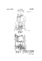
- Fig. 1 is an end elevation of avdomesticlaundry centrifuge containing my improvements
- Fig. 2 is a vertical sectional view corresponding to the line 2--2 of Fig. 1
- Fig. 3 is a horizontal sectional view corresponding to the line 3 3 of Fig. 2
- Fig. 4 shows a modified form of stop and brake mechanism
- Fig. 5 is a top plan view of a modified form f of driving mechanism
- Fig. 6 is an end elevation of the device shown in Fig. 5.
- the centrifuge illustrated in Figs. 1 and 2 comprisesessentially a foraminous basket or container ⁇ 1 concentric about a vertical axis and mounted on a vertical shaft 2, the whole being housed inside an upright metal casing 3, supported by legs 1 -4.
- this casing 3 is a self-contained device but it is within my invention to form it as a part of any other convenient unit such as a washing tub. I have shown the casing as provided with a rigid vtop 5 having a central opening 6 registering with a similar opening in the basket 1 and provided with a cover 7 hinged at 8 and formed with an upturned flange 9 along the end wall ofthe casing.
- the bottom of the casing is formed with a vertical central curb 10 of sufiicient diameter to accommodate the shaft 2 and its attached parts and also spaced sufficiently from the side walls of the casing to define an annular chamber or well 11 for the reception of the extracted liquid, the bottom of this wellbeing provided with a suitable outlet 12.
- the bottom of said container is formed outwardly of the wall 10 with a depending drip rib 13 here defined by the junction between the outer wall of the container and the outwardly and downwardly slanted bottom wall 14 thereof so as to insure the delivery of all the drip to the chamber 11 and preventy it from running down the shaft or fallino through the space inside this wall.
- the shaft 2 is normal to and rotatable with the horizontal circular friction plate 15 by which the container or basket 1s both supported and driven.
- the legs 4 4 are connected in pairs by horizontal members 16--16 which 1n turn are connected by the horizontal girder 17 provided at the center with a vertical elongated bearing sleeve 18 in which 1s mounted the vertical shaft 19 whose upstanding endV receives the hub 20 of the plate 15.
- the lower end of the shaft 2 terminates lin a spider 21 whose arms merge yin the-ring 22 lwhich is secured to this friction plate through the medium of an annular cushioning member 23 of soft rubber or material having the herein essential properties of soft rubber.
- a friction disk 30 Carried by the girder'17 and'by a second girder 25 spaced therefrom are bearings 26, 27 in which is journaled a horizontal shaft 28 on which is mounted :a friction disk 30.
- This disk is not rigidly attached to its shaft but is loosely threaded thereon as indicated at 31, and is yieldingly held adjacent to one end of such thread by means of a spring 32.
- the wheel 33 also serves for the transmission of power to the shaft 28, being connected by a belt 35 toV the drive pulley 36 of a motor-37 4carried by one of the members 16.
- the direction of driving is very important since it must be such as to tend always to screw the shaft 28 into the disk 30 and thereby draw this disk outwardly towards the periphery of the plate 15.
- the machine is so designed that with the motor 37 operating at its full normal speed and the disk 30 at its innermost position as shown in Figs. 2 and 3, the basket 1 will be rotated at its maximum desired velocity.
- the inertia ⁇ ofthe latter causes the motor to overrun, thereby screwing the shaft 28 into the disk 30 and thereby drawing the disk towards the peripheryof the plate 15 thus changing the speed ratio and aifording the motor an increased mechanical advantage.
- the degree of change of ratio depends upon the stiffness of the spring 32, and this depends upon the size and construction of the motor and length of time which the acceleration is designed to cover.
- a hand lever 40 pivoted to a horizontal boss 41 carried by the gi rder 17 and provided with a radial arm 42 to which is journaled a horizontal idler wheel 43.
- This idler is mounted with its axis radial to the shaft 19 and in a position to receive and support the disk 15.
- the extremity of the arm 42 is provided with a brake shoe 45 adapted to engage the disk l5.
- the upper end of the lever 40 projects above the top of the ca sin edge of the flange 9, its motion being guided by a rod 46, carried by the end of the casing, the latter being preferably formed with lugs 47 cooperating with a dog 48 operatively connected in the usual manner with a detent handle 50.
- the elevation of the plate from the disk 30 is advantageous in preserving the disk, which is generally provided with a tire of softer material, from becoming deformed or flattened while the machine is standing. It will be understood that the motor 37 can be used for other purposes also or may be shared with other machinery.
- Figs. 4 and 5 I have illustrated a modified arrangement of brake.
- the same lever l40 is employed and has an arm 42 carrying a roller 43 by which the plate 15 is lifted off the disk 30, but the brake shoe 45EL instead of being carried by this arm is mounted on a part of the casing 1 or its frame above the plate, the latter being elevated into contact with it by the action of the lever40.
- the brake shoe 45EL instead of being carried by this arm is mounted on a part of the casing 1 or its frame above the plate, the latter being elevated into contact with it by the action of the lever40.
- shaft 62 now the driven member instead of the driving member, is mounted in bearings 63-63 so as to traverse the face of the plate 60 and on which -is loosely screwed the friction disk 64 whose face is, as usual, provided with a soft tire 65.
- Power is taken o' the shaft 62 in any suitable manner as by the pulley 66. Screwing of the disk 64 along the shaft is opposed by the spring 67 interposed between said disk and an abutment member 68.
- the disk 64 Upon starting the motor 61, assuming the load on the shaft 62 to be heavy, the disk 64 will be screwed along the shaft to a point nearer the center of the plate 60 where the mechanical advantage is sufiiciently increased to enable the motor 61 to move the same, but as the speed of the shaft 62 increases and its opposition becomes less, the spring 67 gradually returns the disk towards the periphery of the plate until both the driving and the driven member reach their full speed. It will be seen that when the plate is the driving member it is necessary for the disk to move inwardly in order to secure the desired change of speed ratio, but where the plate is the driven member it is necessary for the disk to move outwardly to obtain this result.
- a centrifugal machine in combination, ⁇ a vertical shaft, a horizontal friction plate carried thereby, a pad of material having the herein essential properties of soft rubber carried by said plate, a spider mounted on said pad, an upright shaft carried by said spider, a container carried by said shaft, and a friction disk supporting and driving said plate.
- a centrifugal machine in combination, a vertical shaft, a horizontal friction plate carried thereby, a pad of material having the herein essential properties of soft rubber carried by said plate, a spider mounted on said pad, an upright shaft carried by said spider, a container carried by said shaft, a friction disk adapted to support and drive said plate, and a lever having a part adapted to engage said plate and elevate it out of contact with said disk.
- a frame comprising legs and a horizontal member, a vertical bearing carried by said member, a vertical shaft in said bearing, a horizontal circular plate carried by said shaft, a second vertical shaft carried by said plate, there being a yielding substance between said plate and second shaft, a horizontal shaft journaled to said frame below said plate, a friction disk carried by said last shaft and engaging said plate, and means for driving said last shaft.
- a centrifuge in combination, a horizontal shaft, a disk thereon, a vertically movable horizontal circular plate resting on said disk, a vertical slidable bearing for said plate, a vertical shaft centrally carried by said plate, there being a yielding connection between said plate and vertical shaft, and a rotatable container carried by said vertical shaft.
- said plate and disk constituting the power transmitting means between said driving member and said driven member, the direction of twist of said thread being such that the transmission of ower tends to screw said disk along its sha t to a position to increase the mechanical advantage, and spring means operatively connecting said disk and shaft and tending to move the disk in the opposite direction.
- a centrifugal machine in combination, a vertical shaft, a horizontal friction plate carried thereby, a friction disk adapted to support and drive said plate, a vertical shaft having an elastic gyration-permitting connection to said plate, and a centrifuge container rigidly secured to said shaft.
Landscapes
- Engineering & Computer Science (AREA)
- Textile Engineering (AREA)
- Centrifugal Separators (AREA)
Description
April 12, 1932. J. B. KIRBY CENTRIFUGAL MACHINE Filed June 7, 1926 2 Sheets--Sheei'l B. Kirby g/lwz Atoz-neys pril l2, 1932. I *JQ-B. KlRBY 1,853,866
CENTRIFUGAL MACHINE Filed June 7,v 192e 2 speetS-sheex 2 James Kzry .6 Inventor PL? f77 Mg/ j Attorneys Patented Apr. 12, 1932 UNITED STATES JAMES B. KIRBY, F WEST RICHFIELD, OHIO CENTRIFUGAL MACHINE Application filed .Tune 7, 1926. Serial No. 114,191.
This invention relates chiefiy to centrifugal machines and has for its object the provision of a new and improved driving mechanism therefor which shall facilitate their operation and permit the use of smaller and cheaper motors than heretofore employed; the provlsion of new and improved expedients for applying the full power of the motor for purposes of accelerating the motion without 1o slipping of belts or other friction devices and without danger of overloading the motor the provision of new and improved means for supporting, centering, idling, and braking the device; the provision of new and improved safety devices therefor, while further objects and advantages of the invention will become apparent as the description proceeds.
I have illustrated my improvements in connection with a laundry apparatus by which clothing and fabrics are centrifuged but it will be understood that the same or much similar devices can also be employed for driving cream separators, vehicles, etc., wherein the load and speed are variable and wherein the maximum power available Yis definitely limited.
In the drawings I have chosen for illustrative purposes a simple, self-contained, domestic-laundry, centrifuge, although it will be understood that these drawings are intended to be merely illustrative of the principles of my invention and not limiting upon me as regards either construction or uses.
Fig. 1 is an end elevation of avdomesticlaundry centrifuge containing my improvements; Fig. 2 is a vertical sectional view corresponding to the line 2--2 of Fig. 1; Fig. 3 is a horizontal sectional view corresponding to the line 3 3 of Fig. 2; Fig. 4 shows a modified form of stop and brake mechanism; Fig. 5 is a top plan view of a modified form f of driving mechanism; and Fig. 6 is an end elevation of the device shown in Fig. 5.
\.The centrifuge illustrated in Figs. 1 and 2 comprisesessentially a foraminous basket or container `1 concentric about a vertical axis and mounted on a vertical shaft 2, the whole being housed inside an upright metal casing 3, supported by legs 1 -4. In the present embodiment this casing 3 is a self-contained device but it is within my invention to form it as a part of any other convenient unit such as a washing tub. I have shown the casing as provided with a rigid vtop 5 having a central opening 6 registering with a similar opening in the basket 1 and provided with a cover 7 hinged at 8 and formed with an upturned flange 9 along the end wall ofthe casing. The bottom of the casing is formed with a vertical central curb 10 of sufiicient diameter to accommodate the shaft 2 and its attached parts and also spaced sufficiently from the side walls of the casing to define an annular chamber or well 11 for the reception of the extracted liquid, the bottom of this wellbeing provided with a suitable outlet 12. The bottom of said container is formed outwardly of the wall 10 with a depending drip rib 13 here defined by the junction between the outer wall of the container and the outwardly and downwardly slanted bottom wall 14 thereof so as to insure the delivery of all the drip to the chamber 11 and preventy it from running down the shaft or fallino through the space inside this wall.
According to a preferred form of the device the shaft 2 is normal to and rotatable with the horizontal circular friction plate 15 by which the container or basket 1s both supported and driven. In Ythe present embodiment the legs 4 4 are connected in pairs by horizontal members 16--16 which 1n turn are connected by the horizontal girder 17 provided at the center with a vertical elongated bearing sleeve 18 in which 1s mounted the vertical shaft 19 whose upstanding endV receives the hub 20 of the plate 15. The lower end of the shaft 2 terminates lin a spider 21 whose arms merge yin the-ring 22 lwhich is secured to this friction plate through the medium of an annular cushioning member 23 of soft rubber or material having the herein essential properties of soft rubber.
Carried by the girder'17 and'by a second girder 25 spaced therefrom are bearings 26, 27 in which is journaled a horizontal shaft 28 on which is mounted :a friction disk 30. This disk is not rigidly attached to its shaft but is loosely threaded thereon as indicated at 31, and is yieldingly held adjacent to one end of such thread by means of a spring 32. In the present embodiment the wheel 33 also serves for the transmission of power to the shaft 28, being connected by a belt 35 toV the drive pulley 36 of a motor-37 4carried by one of the members 16. The direction of driving is very important since it must be such as to tend always to screw the shaft 28 into the disk 30 and thereby draw this disk outwardly towards the periphery of the plate 15. The machine is so designed that with the motor 37 operating at its full normal speed and the disk 30 at its innermost position as shown in Figs. 2 and 3, the basket 1 will be rotated at its maximum desired velocity. Upon starting the device, however, especially with a heavy load in the container 1, the inertia` ofthe latter causes the motor to overrun, thereby screwing the shaft 28 into the disk 30 and thereby drawing the disk towards the peripheryof the plate 15 thus changing the speed ratio and aifording the motor an increased mechanical advantage. The degree of change of ratio depends upon the stiffness of the spring 32, and this depends upon the size and construction of the motor and length of time which the acceleration is designed to cover. In the case of a carefully made machine or one mounted 011 ball bearings and running very easily when once started (such as a cream separator) it is possible to employ a very small motor by using a comparatively light spring 32 and permitting a very large decrease in speed ratio, but with the result of requiring a correspondingly lonO' period for acceleration; on the other hand by using a more powerful motor and a stronger spring, the speed ratio is less changed and the acceleration period is shortened. As the container velocity increases and its opposition decreases, the spring 32 gradually restores the disk 30 to its initial position as shown in Figs. 2 and 3 with the result that both the motor and` container are soon running to their respective speeds of highest efiiciency.
In order to control the operation of the container I have shown in Figs. 1, 2, and 3 a hand lever 40 pivoted to a horizontal boss 41 carried by the gi rder 17 and provided with a radial arm 42 to which is journaled a horizontal idler wheel 43. This idler is mounted with its axis radial to the shaft 19 and in a position to receive and support the disk 15.
" The extremity of the arm 42 is provided with a brake shoe 45 adapted to engage the disk l5. The upper end of the lever 40 projects above the top of the ca sin edge of the flange 9, its motion being guided by a rod 46, carried by the end of the casing, the latter being preferably formed with lugs 47 cooperating with a dog 48 operatively connected in the usual manner with a detent handle 50. When the lever stands in the position shown in Fig. 1 the brake shoe 45 and above the I15 is lowered onto the disk 30 which when rotated starts it into operation as heretofore described, the lever now preventing opening of the cover. It is possible either by moving the lever to the half way position to allow the tub to spin freely a long time and come to rest gradually, or by drawing the lever more forcibly to the left to put on the brake with any desired degree of vigor. The elevation of the plate from the disk 30 is advantageous in preserving the disk, which is generally provided with a tire of softer material, from becoming deformed or flattened while the machine is standing. It will be understood that the motor 37 can be used for other purposes also or may be shared with other machinery.
In Figs. 4 and 5 I have illustrated a modified arrangement of brake. The same lever l40 is employed and has an arm 42 carrying a roller 43 by which the plate 15 is lifted off the disk 30, but the brake shoe 45EL instead of being carried by this arm is mounted on a part of the casing 1 or its frame above the plate, the latter being elevated into contact with it by the action of the lever40. In this case it is not always convenient to maintain the brake shoe at such a point as to guarantee the application of the brake at the time the cover is opened as in Fig. 1 although the container is at least lifted olf the power element, and in neither case can the power be applied until the cover is closed.
In Figs. 5 and 6 I have illustrated a. modiication of my invention, the parts being `motor 61 instead of being belted thereto. A.
It will be understood that I have shown herein both a mechanical movement of general utility and a specific machine, namely, a laundry centrifuge, containing such element. Some features of the mechanical movement yare useful with other devices than laundry machines, and some features of the centrifuge are valuable with other driving devices, and some features of each produce their fullest eifect only in combination with the other, so that I do not limit myself except-as specilically recited in my several claims.
Having thus described my invention what I claim is:
1. In a centrifugal machine, in combination,`a vertical shaft, a horizontal friction plate carried thereby, a pad of material having the herein essential properties of soft rubber carried by said plate, a spider mounted on said pad, an upright shaft carried by said spider, a container carried by said shaft, and a friction disk supporting and driving said plate.
2. In a centrifugal machine,.in combination, a vertical shaft, a horizontal friction plate carried thereby, a pad of material having the herein essential properties of soft rubber carried by said plate, a spider mounted on said pad, an upright shaft carried by said spider, a container carried by said shaft, a friction disk adapted to support and drive said plate, and a lever having a part adapted to engage said plate and elevate it out of contact with said disk.
3. In aidevice of the character described,
in combination a frame comprising legs and a horizontal member, a vertical bearing carried by said member, a vertical shaft in said bearing, a horizontal circular plate carried by said shaft, a second vertical shaft carried by said plate, there being a yielding substance between said plate and second shaft, a horizontal shaft journaled to said frame below said plate, a friction disk carried by said last shaft and engaging said plate, and means for driving said last shaft.
4. In a centrifuge, in combination, a horizontal shaft, a disk thereon, a vertically movable horizontal circular plate resting on said disk, a vertical slidable bearing for said plate, a vertical shaft centrally carried by said plate, there being a yielding connection between said plate and vertical shaft, and a rotatable container carried by said vertical shaft.
5. In driving mechanism the combination with a driving member and a driven member, one of which has a friction plate and the other a friction disk whose edge bears against the face of said plate, of a shaft on which said disk is threaded, said plate and disk constituting the power transmitting means between said driving member and said driven member, and a spring yieldingly forcing said disk toward that end of the thread where the mechanical advantage from the driving to the driven member is least.
6. The combination with a friction plate of a rotatable shaft parallel to and spaced from the face thereof and having screw threads thereon, a friction disk screwed on `said shaft, a driving and a driven member,
one attached to said plate and the other to said disk, said plate and disk constituting the power transmitting means between said driving member and said driven member, the direction of twist of said thread being such that the transmission of ower tends to screw said disk along its sha t to a position to increase the mechanical advantage, and spring means operatively connecting said disk and shaft and tending to move the disk in the opposite direction.
7. The combination with a driving member and a driven member, one of which has a friction element and the other of which has a friction disk presented edgewise thereto, of a shaft for said disk parallel to an element of said surface, said shaft and disk being loosely screwthreaded together, and a spring operatively-connecting said disk and shaft and tending to screw the disk in a direction to decrease the mechanical advantage of the drive, said plate and disk constituting the power transmitting means between said driving member and said driven member.
8. The combination with two shafts set at right angles to each other, one of the same being threaded, of a4 friction disk loosely screwed on the threaded shaft, a cooperating friction plate carried Ts'oy the other shaft, a spring secured to said threaded shaft and tending to keep said disk at the high speed end of its thread, and power connections to and from said shafts, said disk and* plate constituting the sole power transmitting connection between said shafts.
9. lin a centrifugal machine, in combination, a vertical shaft, a horizontal friction plate carried thereby, a friction disk adapted to support and drive said plate, a vertical shaft having an elastic gyration-permitting connection to said plate, and a centrifuge container rigidly secured to said shaft.
In testimony whereof hereunto a-iiix my signature.
JAWS B. KIRBY.
Priority Applications (1)
| Application Number | Priority Date | Filing Date | Title |
|---|---|---|---|
| US114191A US1853866A (en) | 1926-06-07 | 1926-06-07 | Centrifugal machine |
Applications Claiming Priority (1)
| Application Number | Priority Date | Filing Date | Title |
|---|---|---|---|
| US114191A US1853866A (en) | 1926-06-07 | 1926-06-07 | Centrifugal machine |
Publications (1)
| Publication Number | Publication Date |
|---|---|
| US1853866A true US1853866A (en) | 1932-04-12 |
Family
ID=22353847
Family Applications (1)
| Application Number | Title | Priority Date | Filing Date |
|---|---|---|---|
| US114191A Expired - Lifetime US1853866A (en) | 1926-06-07 | 1926-06-07 | Centrifugal machine |
Country Status (1)
| Country | Link |
|---|---|
| US (1) | US1853866A (en) |
Cited By (2)
| Publication number | Priority date | Publication date | Assignee | Title |
|---|---|---|---|---|
| US2467739A (en) * | 1945-11-09 | 1949-04-19 | Cread Engineering And Res Comp | Variable-speed power transmission device |
| US3872736A (en) * | 1973-03-16 | 1975-03-25 | Michael P Houvouras | Cycle transmission |
-
1926
- 1926-06-07 US US114191A patent/US1853866A/en not_active Expired - Lifetime
Cited By (2)
| Publication number | Priority date | Publication date | Assignee | Title |
|---|---|---|---|---|
| US2467739A (en) * | 1945-11-09 | 1949-04-19 | Cread Engineering And Res Comp | Variable-speed power transmission device |
| US3872736A (en) * | 1973-03-16 | 1975-03-25 | Michael P Houvouras | Cycle transmission |
Similar Documents
| Publication | Publication Date | Title |
|---|---|---|
| US2538246A (en) | Washing machine | |
| US2826056A (en) | Drive for automatic washer | |
| US2350218A (en) | Washing machine | |
| US2652710A (en) | Combined washing and centrifugal drying machine | |
| US2658372A (en) | Washing machine | |
| US3753297A (en) | Household drying machine | |
| US2533722A (en) | Balancing centrifugal drying and washing machine | |
| US2715826A (en) | Combined washing machine and extractor | |
| US2699683A (en) | Clutch and drive mechanism for washing machines | |
| US2346668A (en) | Washing machine | |
| US2346669A (en) | Washing machine | |
| US2471217A (en) | Rotatable device | |
| US2793757A (en) | Centrifugal-type washing machine | |
| US2555400A (en) | Washing machine with gyratory washing action | |
| US2969172A (en) | Clothes washing machine | |
| US2797569A (en) | Clothes washing machine | |
| US1853866A (en) | Centrifugal machine | |
| US1727933A (en) | Laundry-machine clutch | |
| US2580435A (en) | Washing machine | |
| US2930215A (en) | Tub assembly for washing machine | |
| US2995023A (en) | Pulsator mechanism for washing machines | |
| US2161618A (en) | Washing machine | |
| US2405404A (en) | Domestic appliance | |
| US2520366A (en) | Apparatus for washing clothes | |
| US2091536A (en) | Centrifugal drier |