US1853856A - Well drilling equipment - Google Patents
Well drilling equipment Download PDFInfo
- Publication number
- US1853856A US1853856A US309619A US30961928A US1853856A US 1853856 A US1853856 A US 1853856A US 309619 A US309619 A US 309619A US 30961928 A US30961928 A US 30961928A US 1853856 A US1853856 A US 1853856A
- Authority
- US
- United States
- Prior art keywords
- well
- pipe
- piston
- pressure
- cylinder
- Prior art date
- Legal status (The legal status is an assumption and is not a legal conclusion. Google has not performed a legal analysis and makes no representation as to the accuracy of the status listed.)
- Expired - Lifetime
Links
- 238000005553 drilling Methods 0.000 title description 18
- 210000004907 gland Anatomy 0.000 description 25
- 241000239290 Araneae Species 0.000 description 11
- 239000012530 fluid Substances 0.000 description 8
- 238000012856 packing Methods 0.000 description 7
- 238000010276 construction Methods 0.000 description 6
- 230000000452 restraining effect Effects 0.000 description 6
- 238000011010 flushing procedure Methods 0.000 description 5
- 230000004075 alteration Effects 0.000 description 3
- 230000015572 biosynthetic process Effects 0.000 description 3
- 230000006872 improvement Effects 0.000 description 3
- 230000007246 mechanism Effects 0.000 description 3
- 230000000717 retained effect Effects 0.000 description 3
- 239000007788 liquid Substances 0.000 description 2
- 239000000314 lubricant Substances 0.000 description 2
- 230000009471 action Effects 0.000 description 1
- 238000013459 approach Methods 0.000 description 1
- 230000000712 assembly Effects 0.000 description 1
- 238000000429 assembly Methods 0.000 description 1
- 238000009412 basement excavation Methods 0.000 description 1
- 230000008901 benefit Effects 0.000 description 1
- 230000008859 change Effects 0.000 description 1
- 230000008878 coupling Effects 0.000 description 1
- 238000010168 coupling process Methods 0.000 description 1
- 238000005859 coupling reaction Methods 0.000 description 1
- 238000005520 cutting process Methods 0.000 description 1
- 238000003780 insertion Methods 0.000 description 1
- 230000037431 insertion Effects 0.000 description 1
- 238000005461 lubrication Methods 0.000 description 1
- 210000002445 nipple Anatomy 0.000 description 1
- 230000008439 repair process Effects 0.000 description 1
- 230000000284 resting effect Effects 0.000 description 1
Images
Classifications
-
- E—FIXED CONSTRUCTIONS
- E21—EARTH OR ROCK DRILLING; MINING
- E21B—EARTH OR ROCK DRILLING; OBTAINING OIL, GAS, WATER, SOLUBLE OR MELTABLE MATERIALS OR A SLURRY OF MINERALS FROM WELLS
- E21B33/00—Sealing or packing boreholes or wells
- E21B33/02—Surface sealing or packing
- E21B33/03—Well heads; Setting-up thereof
- E21B33/06—Blow-out preventers, i.e. apparatus closing around a drill pipe, e.g. annular blow-out preventers
Definitions
- Figs. 5 and-6 ar esections sponding lines of Fig. 1.
- the casing head 4 also carries a bullplug 8. which is adapted to be replaced by a line of pipe similar to the line 5, when desired. Such a line may be used as an outlet for the flow of the well.
- a set of inverted slips or other pipe engaging means 43 are supported by the spider 42 in a tapered seat, and, as shown in Fig. 3, are
- a well drilling equipment including a plurality of pipe engaging means, one of said ,means being xed upon the casing head of the well, one being vertically adjustable with respect to said fixed head and another being slidable vertically to carry the pipe therewith, all of said means surrounding said pipe and being coaxial with the pipe to be engaged.
- a well drilling equipment comprising a casing, a casing head, a base member carried by said head, rods carried by said base member, and a spider adjustably mounted on said rods, arms on said base member and a spider carried by said arms, each of saidspiders havlng a set of pipe engaging means therein, thru both of said spiders and adapted to support a pipe controlling mechanism.
- a well drilling equipment comprising oppositely disposed drill pipe engaging means adapted to restrain movement o the pipe longitudinally, a cylinder mounted above said means and coaxial with said pipe, and pres- .to be entirely'satisfactory and practical for y sure controlled means in said cylinder to compel movement of the drill stem against internal well pressure, supports for said cylinder which permit access ⁇ to the drill pipe.
- asmeans to compel or restrain movement of a drill pipe in a well having internal pressures 1n excess of the weight of said pipe said means comprising a cylinder, a piston therein, pipe engaging means carried by said piston and iuid pressure for compelling or restraining movement of said piston, and additional means movable by said piston to prevent buckling of said pipe, and a cushioning spring for said piston operable to seat said pipe enaging means, and additional means carried Ey said dpiston and normally ltending to unseat sai pipe engaging means.
Landscapes
- Life Sciences & Earth Sciences (AREA)
- Engineering & Computer Science (AREA)
- Geology (AREA)
- Mining & Mineral Resources (AREA)
- Physics & Mathematics (AREA)
- Environmental & Geological Engineering (AREA)
- Fluid Mechanics (AREA)
- General Life Sciences & Earth Sciences (AREA)
- Geochemistry & Mineralogy (AREA)
- Earth Drilling (AREA)
Description
April 12, 1932-' u w. s. @AT1-REM.` l 1,853,856
Y WELLDRILLING EQUIPMENT y v Filed oct. 1, 1928 1 3 sheets-sheet 1 6 EME e LEZ April 12, 1932. 'W s, GATTRELL 1,853,856
WELL DRILLING'EQUIPMENT I Filed oct. 1, 1928 3 sheets-Sheet 2 56' E .55 ffl Q o -O- O E 7 E 4e 5 A 44 '132 V s q 2 3/ 3 'Ef April 12, 1932- W. s. GATTRELL Y WELL DRILLING EQUIPMENT 3 Sheets-Sheet Filed OCC. l, 1928 Patented 12, 1932 UNITED l s'rA-Tlazs PATENT oFFieE WILLIAM S. G rATTRELIJ, F LEES SUMMIT, MISSOURI WELL DEILLING EQUIPMENT Application filed October 1, 1928. Serial No 309,619.
y The present device is similar in some respects tothat disclosed in my eo-pending application filed April 30, 1926, Serial No. 103,- 191, but embodies certain improvements and points of distinction therefrom,
In drilling wells with a .rotary drilling equipment in localities where gas pressure 1n the well is common, there is always the danger of the gas pressure overcoming the weight of n the drill stem and the flushing fluid in the 0 Well; when this Voccurs itis termed a blow-out and usually results in wrecking the well,
- derrick'and all adjacent equipment. Blowout preventers and other similar devices have been constructed but with most of them now pressure exists or to safely remove or insert the drill stem.
It is an object of my invention to equip the well in such a manner that the drill pipe may be manipulated in a well under pressure without danger of a blow-out. It is aparticular object of the invention to allow the removal of the drill stem lfrom the well under high pressure and to control the flow of gas and liquid from the well when' the high pressure stratum is encountered.
A further object is to provide a device capable ofpaccommodating one or more sections of the drill stem and which is readily remov- I able to be placed in one corner of the derrick Where it will be readily available when pressure in the'well is impending.
A further object is toconstruct the device v so that by a slight alteration `the restraining force may be applied to permit removal or to compel insertion of the drill stem.
Another object is to incorporate in my device novel glands, oiling devices, slip constructions andl assemblies and to otherwise imavailable it is impossible to drill while the.
prove the structure thereof to obtain a simple, practical mechanism as will be readily apparent to those skilled in the art to which my improvement appertains.
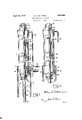
In the accompanying drawings Fig. 1 shows a vertical elevation, partly broken away to show the internal construction of the control cylinder'of my mechanism, this particular assembly being adapted for removing thevdrill or other tubing from the well under a pressure which would tend to blow the pipe from the well.
Fig. 2 is similar to Fig. 1 but shows the arrangement within the cylinder in orderto insert the tubing into a well under pressure.
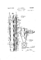
Fig. 3 is a partial elevation and a partial section of the device adjacent the derrick platform and upon which the cylinder of either Fia'. 1 or Fig. 3 is adapted to be supported.
Fig. 4 is an elevation, partly broken away, of the casing head, outlet and gate valvesand is a continuation of Fig. 3.
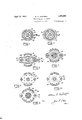
Figs. 5 and-6 ar esections sponding lines of Fig. 1.
Figs. 7 to 11 inclusive are'sections taken on corresponding lines of Fig. 3.
The structure oftlny improved device will be most readily apparent by having reference to Fig. 4, which shows the -usual well casing at l, with a gate valve 2, swaged nipple 3 and a specially constructedcasing head 4 disposed 8 one upon the other with threaded engagement, and being of such diameter as to permit passage of the drill stem, tools, etc. The casing head 4 has a lateral mud line as at 5, which carries a shutlo valve 6. It is through this line that the flushing fluid and desired pressures are admitted to and released from the well bore. It will be noted thatthe n'ipple 3 has a beveled upper end or lip 7 which is adapted to seat in al corresponding formation in the casing head 4. This formation gives a smoothpassage thru the members `and serves to further prevent leaking at this joint.
The casing head 4 also carries a bullplug 8. which is adapted to be replaced by a line of pipe similar to the line 5, when desired. Such a line may be used as an outlet for the flow of the well.
The upper end of the casing head 4 is best taken on correber 12, which is constructed tocarry the load of my improved device about to be disclosed.
This connection 12 is specially formed, one of the novel features being an oiling passage 13 which extends inwardly and downwardly to terminate in a cavit-y or a plurality of opento the drill stem 15. It has been difficult in the past `to obtain proper lubrication of the Y drill tubing when the well is under pressure' and the packing glands are quickly 'displaced and destroyed, whereas with the passage just described lubricant may be forced into the cavity 14, as desired It must be remembered that the present device'is constructed to withstand high pressures and to this `end a triple gland structure has been provided, as shown at 18, 19 and 20. Y
' The gland 18 is formed for sliding adjustnient instead of being threaded into the base 12, and bolts 22 are threaded into the base and pass thru openings in the iange 24 of the gland. Thus by adjusting the nuts 25 any desired pressure may be exerted upon the packing 26 in either direction. This sliding I type gland has been provided, as in rotary equipment, the drill stem gradually tightens the threaded type of gland and destroys the packing o-r twists oii' `the, gland. With the gland 18, as here shown, the plurality of bolts provided, as will be seen from Fig. 11, prevent any tendency of the gland to rotate and a'serviceablepackingisthus retained. The nuts above and below the iiange prevent the drill pipe from moving the gland in either direction. This gland 18 is located inan enlarged annular seat in the base 12 and surrour ds the larger gland 19 which is similar in construction to that of 18 and has a ilange 27 to receive the bolts 22. See Fig. 10. The gland 19, however, is provided with an upwardly extending portion 28, having a cavity to receive the packing 29, top gland 20,
flange' 31 and nuts 32, which have adjusting bolts23 threaded into the flange 30 of the portion 28. See Fig. 9. Tt will be noted that the anges-24, 27 and 31 are somewhat oval in shape, as shown in Figs. 9 and 10, and at their ends are divided to form portions which extend aboutl the rods 40. These portions may abut against the rods to prevent rotation of the glands and act as a further means, in addition to the bolts described, to retain the glands in a rigid position. it will I be apparent from the assembly of glands that v been-provided.
any lealn'ng along the drill tubing 'will bev entirely eliminated and that readily adjust-l able, serviceable, non-rotatable packing has The equipment I4 have provided to facilii tate handling of the drill pipe under pressure is shown. in Figs. 1 and 3, Fig. 3 being a, continuation'of Fig. 1. This structure comprises the supporting rods 40,`threaded or otherwise removably aiXed to the support 12 and shown in section in Figs. 7 to 11. These rods 40 are threaded thruout most of their length and, as stated, pass thru the divided ends of the flanges 27 and 31 to the glands. Threaded onto the rods 40v are Y, sleeves 41 which carry a spider 42. Rotationl ings 14 in order that lubricant may be fed.`
of the sleeves thus causes the spider 42 to travel up or down as desired on the rods. A set of inverted slips or other pipe engaging means 43 are supported by the spider 42 in a tapered seat, and, as shown in Fig. 3, are
hinged at 44 by means of a lever 45 and collar 46. See Fig. 7. This set of slips is adapted to grip the tubing or pipe when the pressure in the well tends to force it upwardly. The slips 43 are shown in theirnormal position and ready at all times to instantly grip the tubing. Above the spider 42 is a second spider 50 which is supported on the base 12 byv means of arms 51, also shown in Figs. 7 to 11. This spider 50 carries a second retained in active position by means of a spring 58 attached to each. By manipulation of the-sleeves 41 any locking of both sets of slips may be avoided.
yThe rods 40 pass thru openings in the spider 50 and extend thereabove, providing a'detaehable connection 60 for the supports 61, show in both Figs. 1 and 3. Thederrick floor is preferably at about the level of these connections 60 so that the structure thereabove, and yet to be described, may be rel moved.f The casing head 4, rods 40, spiders 42and 50 are all disposed in what is usually termed the cellar, which is an excavation at the surface of the ground.` However, in some instances, the derrick floor is elevated above the ground and the cellar then is of less depth. The present structure requires a cellar of about ten and ahalf feet, which yis about the depth usually employed. Tt is desirable that the slip levers 45 and los with forms a tool joint which will read-v ily slide or rotate in the glands. When it is desired to remove a tool the stem is withdrawn, or. if under pressure, permitted to rise until the tool abuts the base member 12, the gate valve 2 is thenclosed below the tool and the entire deviceA unscrewed` at 10, raised above the derrick floor by any suitable elevator, and the tool is changed or the desired operation performed. A packing ring 11 is shown between the casing head 4 and base member 12. a
The supports 61 extend above the derrick floor for considerable length fand gradually change in cross section to take the forni shown in Fig. 6, and have attached thereto the coupling whichforms the base of a pressure cylinder 71,v used to` control the movement of the drill'stem. This cylinder comprises a section 72 of pipe, which may be about thirty or more feet in length, depending upon the pipe sections being handled and is closed at the upper end by a cap 73 and gland 74 similar in construction to the gland 18 previously described. Within the cylinder 71 is a fluid-tight piston 75 having packings 76 and 77 thereon and retained in position by glands and bolts 78 and 79, respectively. The lower side of this pist-on has an upwardlyftapering seat adapted to receive a set of slips or other suitable pipe engaging means 80. In the structure, as shown in Figs. 1 and 5, the slips 80 carry bolts 81, which retain an annular plate 8.2. Between this plate and the piston 75 is a coil spring 83 normally spacing the plate 82 away from the piston and thru the bolts 81, maintaining the slips 8() withdrawn from the seat. A i large coil spring 84 is disposed in the .base of the cylinder 71 and is adapted to receive the plate 82 when the piston approaches the lowermost position. VThe spring 84 then due to the weight of the piston 75 or to pressure exerted thereon from above compresses the smaller spring 83 and forces the slips 8O intothe seat of the piston, and to engaging position on the drill stem 15. A pressure line 85 is shown as leading to the upper end of the cylinder 71 and by means f the hand valve 86 any desired .pressure may be maintained on the piston to control the upward movement thereof. It is presumed that the tubing at this time is exerting an upward thrust due to the fluid pressure in the well. Thus a joint adjacent the derrick floor isloosened preparatory to being disconnected. While the pipe is gripped by the slips 43, the piston 75 is lowered and the pipe gripped by the slips 80 sufiicient pressure is placed in the upper cylinder 71 to oppose the well pressure. The slips 43are then loosened by the lever 45 and the piston 75 allowed tobe forced upwardly by the tubing and slips'80.
The loosened joint adjacent the derrick floor passes into the cylinder 71 and the piston rises with the stem, restraining it until the piston reaches almost'the top of the cylinder. The slips 43 are again allowed to grip the stem until the slips 80 release in order that the piston 75 may again be lowered and the operation repeated. The loosened joint on the second trip appears above the cap 73 and the sections above it in the derrick are disconnected. The hoisting of the tubing is repeated until the topmost end is within about the next tool joint appears at the derrick floor it is loosened as before and the entire circle of operation is repeated. By this means two or more sections of stem may be removed undei absolutely safe conditions.
The piston 75 is provided with additional safety means in event enormous pressures are encountered. This means includes the bolts 90 on the underside of the piston, which have attached thereto chains 91 and which are in turn connected'with .a cup-shaped annular ring .92 resting in the base of the cylinder. These chains are arranged so that they are about one half the length of the path of travel of the piston 75. Thus when the piston has been raised half way up the cylinder the chains begin to lift the cup 92, which thereafter slides upwardly but acts as a bushing or support as regards the stem 15 supporting it and preventing any buckling which might otherwise occur. This ring 92 also serves. as an abutting shoulder for the piston 75 when the spring. 84V' is compressed and prevents injuryto the bolts`81 and plate 82.
A pressure line 93 with a valve 94 is connected to the base of the cylinder 71 and may be used to force. the piston upwardly -or to cushion it on.v the downward stroke as desired. The `ring 92 has openings, 96 ad jacent the cavity 97 to admit the pressure vfluid which may be either liquid or gas, as
convenient. VIt would be possible to connect the lines 85 and 93 to the natural pressure in 4the well, if desired, as the exposed area of a section length of the top of the derrick. As
nection so that a single pipe line is suiicientv to release the pressure fromthe cylinder 71 or an exhaust pipe andvalve may be used.
The base of the cylinder 71 is made readily removable by forming a base 95, similar to the cap 73, and carrying a'gland 98, similar to 74. `This lower cap may be removed for purposes or repairs, or 4replacements to the piston 75, or other parts.
The apparatus just described is preferably used to restrain the tubing while inthe well bore or to safely remove it under pressure which tend to force the tubing from the well.
CII
Such structure as shownin Fig. l is desirable when the well blows in and it is necessary to restrain the tubing, or to remove it, or to retain it in any one position. Thusgif pressure suddenly develops the slips 43 instantly grip the tubing as it starts up. The cylinder 71 v is then attached at 61 and the tubing hitched lbobbing of the tubing is instantly controlled.
When the well is subject to 'a heavy internal pressure, drilling can -proceed best when the weight of the drill stem and tool is greater than the pressure in the well. It is,
therefore, necessary to provide a device to insert thel stem and tool in the well against this pressure until the pressure is overcome by the weight of the stem. To provide for such a situation, I have arranged-for a slight alteration of the structure within the cylinder 71, which will enable the operator to orce the drill stem into the well in much the samemanner as it was hitched out. This construction is shown in Fig. 2 and varies .from that 'of Fig. 1 only in the arrangement of the spring 83. As stated, the spring 83 1 of Fig. 1 normally unseated the slips 80, Whereas the spring 83 of Fig. 2 is adapted to normally seat the slips 80. This is provided for by inserting a ring 99 against which thespring 83 abuts and which rests against the slips 80. rllhe cushion spring 84 may be removed when this form is in use if desired.
It will be seen that the action of this form is similar except that the slips engage thel tubing at the top of cylinder 71, and by pressure from the line 85 the piston 71 is forced ydownwardly carrying with it the tubing. The slips 43 are brought into play and grip the tube until the' piston is raised to secure another hold, on the tube. Other i than the'changes here set out, Fig. 2 shows the same structure as Fig. 1. The alterations are quickly` made to the form of Fig. 1, but have been shown as a separate construction for clearness. i
The cylinder? 1 is adapted to stand on and be supported by the member 61 so that it may be placed in one corner of the derrick and occupy the same space as a section of casing but is immediately available for use when l needed.
There is still another advantage to be obtained with my improved device in that the arrangement of tight glands and casing head would permit all the flushing fluid to be `said rods passing blown from the well by compressed air or gas. f The drill stem and vtool could be inserted before or after the .flushing fluid had been discharged. Drilling could then proceed and with my device the cuttings could be blown and carried awayby the compressed air or gas, thus dispensing entirely with the use of flushing fluid. This would be especially advantageous in drilling in the well with a rotary as the mud would not be present to mud oi the formation.
I have disclosed herein an embodiment of my present improvements which I believe the purposes 1n view. IlNevertheless, it is to be understood that the several essential parts of the improved embodiment might be constructed in various other alternative forms, and it is accordingly to be understood that 1n the further development of the device that l reserve the privilege of resorting to all such legitimate changes therein as may be fa1rly embodied within the spirit and scope of the invention as claimed. i
Having described my invention, what I desire to secure by Letters Patent is:
1. A well drilling equipment including a plurality of pipe engaging means, one of said ,means being xed upon the casing head of the well, one being vertically adjustable with respect to said fixed head and another being slidable vertically to carry the pipe therewith, all of said means surrounding said pipe and being coaxial with the pipe to be engaged.
2. A well drilling equipment including two sets of oppositely disposed pipe engaging means adapted to restrain movement of a drill pipe longitudinally and another pipe engaging means surrounding said pipe and adapted to restrain or compel movement of said drill pipe against internal well pressure, all of saidsmeans being coaxial.
3. A well drilling equipment comprising a casing, a casing head, a base member carried by said head, rods carried by said base member, and a spider adjustably mounted on said rods, arms on said base member and a spider carried by said arms, each of saidspiders havlng a set of pipe engaging means therein, thru both of said spiders and adapted to support a pipe controlling mechanism.
4. A well drilling equipment comprising `opposit'ely disposed drill pipe engaging means adapted to restrain movement of the pipe longitudinally, a cylinder mounted above said means and coaxial with said pipe, and pressure controlled .means in said cylinder to compel movement of the drill stem against internal well pressure.
5. A well drilling equipment comprising oppositely disposed drill pipe engaging means adapted to restrain movement o the pipe longitudinally, a cylinder mounted above said means and coaxial with said pipe, and pres- .to be entirely'satisfactory and practical for y sure controlled means in said cylinder to compel movement of the drill stem against internal well pressure, supports for said cylinder which permit access `to the drill pipe.
. 6. In a Well drilling equipment, a means to compel or restrain movement of a drill pipe in' a Well having internal pressures in excess of the Weight ofthe said pipe, said means comprising a cylinder, a piston therein, pipe ,n engaging means forming a part of said iston and also Within said cylinder and uid pressure for compelling or restraining movement of said piston.
7. In a Well drilling equipment, a means to compel or restrain movement of a' drill pipe in a Well having internal pressures in excess of the weight of said pipe, said means comprising a cylinder, a iston therein, pipe engaging means carried y said piston and fluid 2Q pressure for compelling ror restraining move? ment of said piston and additional means movable by said piston to prevent buckling of said pipe. A
8. In a Well drilling equipment, a means to compel or restrain movement of the drill pipe in a Well having internal pressures 1n excess of the weight of said pipe, said means comprising a cylinder, a piston therein, pipe engaging means carried by said. piston and 3o iuid pressure for compelling or restraining movement of said piston, and additional means movable by said piston to prevent buckling of said pipe, and a cushioning spring for said piston operable to seat said pipe engaging means.
9. In a Well drilling equipment, asmeans to compel or restrain movement of a drill pipe in a well having internal pressures 1n excess of the weight of said pipe, said means comprising a cylinder, a piston therein, pipe engaging means carried by said piston and iuid pressure for compelling or restraining movement of said piston, and additional means movable by said piston to prevent buckling of said pipe, and a cushioning spring for said piston operable to seat said pipe enaging means, and additional means carried Ey said dpiston and normally ltending to unseat sai pipe engaging means.
10. A well drilling equipment comprising pipe engaging means anchored to the well casing, a fluid pressure cylinder surmounting said means and also anchored to the well casing, pipe engaging means slidably dis- -5.5 posed in said cylinder to restrain or compel movement of the drill stem for at least a distance equal to a section length thereof;
In testimony whereof I hereunto ailix my signature this 24 day of Sept., A. D. 1928.
WHJLIAM S. 4GrATTRELL.
Priority Applications (1)
| Application Number | Priority Date | Filing Date | Title |
|---|---|---|---|
| US309619A US1853856A (en) | 1928-10-01 | 1928-10-01 | Well drilling equipment |
Applications Claiming Priority (1)
| Application Number | Priority Date | Filing Date | Title |
|---|---|---|---|
| US309619A US1853856A (en) | 1928-10-01 | 1928-10-01 | Well drilling equipment |
Publications (1)
| Publication Number | Publication Date |
|---|---|
| US1853856A true US1853856A (en) | 1932-04-12 |
Family
ID=23198949
Family Applications (1)
| Application Number | Title | Priority Date | Filing Date |
|---|---|---|---|
| US309619A Expired - Lifetime US1853856A (en) | 1928-10-01 | 1928-10-01 | Well drilling equipment |
Country Status (1)
| Country | Link |
|---|---|
| US (1) | US1853856A (en) |
Cited By (7)
| Publication number | Priority date | Publication date | Assignee | Title |
|---|---|---|---|---|
| US2786532A (en) * | 1949-05-17 | 1957-03-26 | Vera Neva Creighton | Floating support for well tubings |
| US2941598A (en) * | 1958-02-10 | 1960-06-21 | Dresser Ind | Wireline feed-in device |
| US2998071A (en) * | 1958-02-10 | 1961-08-29 | Dresser Ind | Wireline feed-in device |
| US3076245A (en) * | 1960-05-16 | 1963-02-05 | Acker Drill Company Inc | Automatic chucking device for drill pipe |
| US3090640A (en) * | 1959-05-04 | 1963-05-21 | Shell Oil Co | Well casing and tubing suspension assembly |
| US3133469A (en) * | 1960-01-29 | 1964-05-19 | Nitroglycerin Aktiebolag | Device for axial displacement of a pipe, rod or the like elongated member |
| US3215203A (en) * | 1961-04-17 | 1965-11-02 | Otis Eng Co | Apparatus for moving a well flow conductor into or out of a well |
-
1928
- 1928-10-01 US US309619A patent/US1853856A/en not_active Expired - Lifetime
Cited By (7)
| Publication number | Priority date | Publication date | Assignee | Title |
|---|---|---|---|---|
| US2786532A (en) * | 1949-05-17 | 1957-03-26 | Vera Neva Creighton | Floating support for well tubings |
| US2941598A (en) * | 1958-02-10 | 1960-06-21 | Dresser Ind | Wireline feed-in device |
| US2998071A (en) * | 1958-02-10 | 1961-08-29 | Dresser Ind | Wireline feed-in device |
| US3090640A (en) * | 1959-05-04 | 1963-05-21 | Shell Oil Co | Well casing and tubing suspension assembly |
| US3133469A (en) * | 1960-01-29 | 1964-05-19 | Nitroglycerin Aktiebolag | Device for axial displacement of a pipe, rod or the like elongated member |
| US3076245A (en) * | 1960-05-16 | 1963-02-05 | Acker Drill Company Inc | Automatic chucking device for drill pipe |
| US3215203A (en) * | 1961-04-17 | 1965-11-02 | Otis Eng Co | Apparatus for moving a well flow conductor into or out of a well |
Similar Documents
| Publication | Publication Date | Title |
|---|---|---|
| US5988274A (en) | Method of and apparatus for inserting pipes and tools into wells | |
| US4516634A (en) | Hydraulic running and setting tool for well packer | |
| US4030354A (en) | Testing of ram and annular blowout preventers | |
| US5515926A (en) | Apparatus and method for installing coiled tubing in a well | |
| US4253521A (en) | Setting tool | |
| EP0460902B1 (en) | Drill pipe bridge plug and method of use | |
| US5191939A (en) | Casing circulator and method | |
| US6712147B2 (en) | Spool for pressure containment used in rigless well completion, re-completion, servicing or workover | |
| US6695064B2 (en) | Slip spool and method of using same | |
| CA2077167C (en) | Wellhead isolation tool and method of use | |
| US5568837A (en) | Method of inserting tubing into live wells | |
| US6948565B2 (en) | Slip spool and method of using same | |
| EP0097457A2 (en) | Apparatus for setting a well tool in a well bore | |
| US5332044A (en) | Wellhead isolation tool and method of use | |
| US6390194B1 (en) | Method and apparatus for multi-diameter testing of blowout preventer assemblies | |
| US4881598A (en) | Blow-out preventor test tool | |
| US2721614A (en) | Systems and structure for controlling the movement of well pipe in well bores | |
| US1853856A (en) | Well drilling equipment | |
| US1944840A (en) | Control head for wells | |
| US2139983A (en) | Back pressure plug valve | |
| US5203410A (en) | Blowout safety system for snubbing equipment | |
| US4436149A (en) | Hydraulic setting tool | |
| US2307662A (en) | Means for controlling wells | |
| US12612836B2 (en) | Through BOP lubrication system | |
| US3316969A (en) | Method of setting hydraulic packers |