US1853855A - Packing device - Google Patents
Packing device Download PDFInfo
- Publication number
- US1853855A US1853855A US248735A US24873528A US1853855A US 1853855 A US1853855 A US 1853855A US 248735 A US248735 A US 248735A US 24873528 A US24873528 A US 24873528A US 1853855 A US1853855 A US 1853855A
- Authority
- US
- United States
- Prior art keywords
- packing
- gland
- drill stem
- seat
- gas
- Prior art date
- Legal status (The legal status is an assumption and is not a legal conclusion. Google has not performed a legal analysis and makes no representation as to the accuracy of the status listed.)
- Expired - Lifetime
Links
- 238000012856 packing Methods 0.000 title description 31
- 210000004907 gland Anatomy 0.000 description 26
- 238000005553 drilling Methods 0.000 description 4
- 230000008878 coupling Effects 0.000 description 3
- 238000010168 coupling process Methods 0.000 description 3
- 238000005859 coupling reaction Methods 0.000 description 3
- 230000008014 freezing Effects 0.000 description 2
- 238000007710 freezing Methods 0.000 description 2
- 239000000314 lubricant Substances 0.000 description 2
- 230000015572 biosynthetic process Effects 0.000 description 1
- 238000010276 construction Methods 0.000 description 1
- 230000001050 lubricating effect Effects 0.000 description 1
- 229920000136 polysorbate Polymers 0.000 description 1
Images
Classifications
-
- E—FIXED CONSTRUCTIONS
- E21—EARTH OR ROCK DRILLING; MINING
- E21B—EARTH OR ROCK DRILLING; OBTAINING OIL, GAS, WATER, SOLUBLE OR MELTABLE MATERIALS OR A SLURRY OF MINERALS FROM WELLS
- E21B33/00—Sealing or packing boreholes or wells
- E21B33/02—Surface sealing or packing
- E21B33/03—Well heads; Setting-up thereof
- E21B33/06—Blow-out preventers, i.e. apparatus closing around a drill pipe, e.g. annular blow-out preventers
Definitions
- My invention relates to packing means to seal oil the space within a casing head and about a flush joint drill stem in well drill-
- a well must be drilled into a producing formation which has a high gas pressure tending to blow the tools from the well. When such conditions are encoun-.
- Fig. 1 illustrates a side view partly in elevation and partly in vertical section,'illustrating the application of my invention.
- Fig. 2 is a transverse section taken on the plane. 2-2 of Fig. 1.
- This device is shown as applied to a casing head of the same general structure as the one disclosed in my copending applica-.
- the structure is adapted to be connected with'the casing head employed in drilling.
- I have a lower tool'joint member 1, whichis threaded at 2 to engage with the casing head after the manner of an ordinary" tool oint.
- a shoulder 3 At the upper end of the threaded shank there is a shoulder 3, which may have a lower groove't therein to receive packing, so as to'assure a tight joint between the coupling and'the casing head.
- the upper end of thetool Joint member has a shoulder 5, upon which supporting posts 6 aremounted,
- the interior of the tooljoint member is provided with a recess, the lower end 9 of V which forms a. seat for packing, and Icontemplate em'ployinga flexible packing indicated at 10, which may be compressed in said seat by a gland 11.
- This gland is of the full width of the recess at its lower end and'hasan annular outwardly flaring skirt 12, but is in turn recessed on itsouter facefto provide a seat 13 to receive further packing 14: be-' tween the gland and the'inner wall of the recess within the joint.
- This packing 14 is adaptedto be compressed within'its' seat by a,
- gland 115 comprising a sleeve fitting-slidably upon the outer surface of the gland 11,'and adapted to be moved downwardly into-said seat-by-means of threaded bolts or'sha'fts 16, i which are 7 extended through a marginal flange 17 on the gland and which are secured also serving as spacin'gfeleat their upper ends within the gland 11.
- a nut 18 upon each of the bolts 16 is adapted to screw downwardly on said bolts to adjust the gland 15.
- This flange is formed with threaded openings to receive the bolts 21 secured at their lower ends within the oint member 1,
- Theupper portion 23 of the gland 11 is re Stepd to form an inner seat at to. receive packing 25, whichniay be compressed by a gland 26 shaped to fit about the drill stem.
- the gland 26 is adjusted through. a bolt. 27, supported at its lower end within a flange 28 on the gland 23 and extending through the fiange29 on the gland 26.
- the flanges upon .the two glands 11: and 26 are formed with recesses or notches to receive the posts 6 previously referred to,
- .JTHLY employ a threaded-plug 82 at the upper and of this oil channel to close the same after said channel has been filled with lubricant.
- the packing will be adjusted looselyso asnot to wear against the drill stem, but. when any stratum has been encountered which gives indications of gas pressure or of 011, the two packing elements 25. and 14 will be adjusted first. This will be done by securing the glands 26 and down- .wardly upon these packing elements.
- lower packing 14 prevents the escape of gas on the outside of the gland and between the same and the tool joint.
- the driller will be able to rotate his drill stem and move the same downwardly into the well and be thus protected against the blowout of gas.
- a multiple stage stuffing box for use about a tube includingv a joint member, a packing seat therein, packing on said seat, a, gland having a body portion in contact with said tube, an. outwardly flaring skirt on the lower end adapted to contact said packing, a second packing in said first seat but overlying said skirt, a second gland forsaid second packing, and means to adjust said glands independently or together.
Landscapes
- Life Sciences & Earth Sciences (AREA)
- Engineering & Computer Science (AREA)
- Geology (AREA)
- Mining & Mineral Resources (AREA)
- Physics & Mathematics (AREA)
- Environmental & Geological Engineering (AREA)
- Fluid Mechanics (AREA)
- General Life Sciences & Earth Sciences (AREA)
- Geochemistry & Mineralogy (AREA)
- Earth Drilling (AREA)
Description
A ril 12, 1932.
W. S. GATTRELL PACKING DEVICE Filed Jan. 25, 1928 3 1 N VEN TOR.
2 wzz/ewci'ir/wzzz,
ATTORNEY.
Patented Apr. 12, 1932 {TED STATES PATENT. OFFICE T P WILLIAM SLOVERGATTRELL, OF ALAMO, VEIBA CRUZ, MEXICO PACKING DEVICE v Applicationfiledfl'aihuary 23, 1928. Serial No. 248,735.
My invention relates to packing means to seal oil the space within a casing head and about a flush joint drill stem in well drill- In many cases a well must be drilled into a producing formation which has a high gas pressure tending to blow the tools from the well. When such conditions are encoun-.
'tered, in rotary drilling, it becomes necessary to equip the drilling rig to take care of the gas'pressures and prevent blowouts. The drill stem is sometimes coupled together with flush couplings so that a stuffing box may be formed in the casinghead'through which the drill stem may pass andstill prewill freeze due to the expansion of the gas coming from the well under pressure. There: is such a low temperature at the point of escape-of the gas that the packing is frozen tight to the'casing and to the gland.
It is an object of my invention to provide means for lubricating the packing in such manner as to avoid its freezing to the casing and the gland. It is also desired, to provide a plurality of adjustable packing devices arranged between the casing head and the drill stem, so that if one packing fails, through mutilation or otherwise, there will H be other devices which are securely packed to prevent accidental blowout of the well.
It is desired to provide a complete assembly foratt-achment to the casing head which will be capable of movement as aunit, but which will provide a plurality of means for preventing the escape of gas between the drill stem and the casing head. It is afurther object to so construct the device that the packing elements will be prevented from rotation during the operation of thedrill stein.
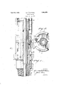
Referring to: the drawings, Fig. 1 illustrates a side view partly in elevation and partly in vertical section,'illustrating the application of my invention. Fig. 2 is a transverse section taken on the plane. 2-2 of Fig. 1.
This device is shown as applied to a casing head of the same general structure as the one disclosed in my copending applica-.
tion No. 103,191, filed April 20, 1926, n a
well drilling equipment.
The structure is adapted to be connected with'the casing head employed in drilling. I have a lower tool'joint member 1, whichis threaded at 2 to engage with the casing head after the manner of an ordinary" tool oint. At the upper end of the threaded shank there is a shoulder 3, which may have a lower groove't therein to receive packing, so as to'assure a tight joint between the coupling and'the casing head. -The upper end of thetool Joint member has a shoulder 5, upon which supporting posts 6 aremounted,
these posts acting to connect with pipes su'p-,
portlng elements not'shown and forming no. 5
part of thisinvention. As willbe seen from Fig.2, there are also plates 7 connected by, bolts 8 to the outersurface of the tool joint I and extending upwardly on each side of the. drill stem and ments. 5
The interior of the tooljoint member is provided with a recess, the lower end 9 of V which forms a. seat for packing, and Icontemplate em'ployinga flexible packing indicated at 10, which may be compressed in said seat by a gland 11. This gland is of the full width of the recess at its lower end and'hasan annular outwardly flaring skirt 12, but is in turn recessed on itsouter facefto provide a seat 13 to receive further packing 14: be-' tween the gland and the'inner wall of the recess within the joint. This packing 14 is adaptedto be compressed within'its' seat by a,
gland 115, comprising a sleeve fitting-slidably upon the outer surface of the gland 11,'and adapted to be moved downwardly into-said seat-by-means of threaded bolts or'sha'fts 16, i which are 7 extended through a marginal flange 17 on the gland and which are secured also serving as spacin'gfeleat their upper ends within the gland 11. A nut 18 upon each of the bolts 16 is adapted to screw downwardly on said bolts to adjust the gland 15.
I gland. This flange is formed with threaded openings to receive the bolts 21 secured at their lower ends within the oint member 1,
. Nuts 22 on said bolts serve-to adjust the gland 11 in an obvious manner.
.Theupper portion 23 of the gland 11 is re cessed to form an inner seat at to. receive packing 25, whichniay be compressed by a gland 26 shaped to fit about the drill stem.
and within a. recess 2%. The gland 26 is adjusted through. a bolt. 27, supported at its lower end within a flange 28 on the gland 23 and extending through the fiange29 on the gland 26. The flanges upon .the two glands 11: and 26 are formed with recesses or notches to receive the posts 6 previously referred to,
.- so. as to prevent'the rotation of the packing elements during the rotation of the drill stem.
. In the operation of my device, I find that "it-is desirable to lubricate the drill stem in such manner as to preventits freezing to the packing 10. .This can best be accomplished .by a series of' oil channels 30 formed in the coupling or joint 1 and extending into said o1ntso asto deliver lubricant at 31 below the )ackin as will'be obvious from Fi 1. I
.JTHLY employ a threaded-plug 82 at the upper and of this oil channel to close the same after said channel has been filled with lubricant.
VVhen the drill stem is rotating under ordinary circumstances .the packing will be adjusted looselyso asnot to wear against the drill stem, but. when any stratum has been encountered which gives indications of gas pressure or of 011, the two packing elements 25. and 14 will be adjusted first. This will be done by securing the glands 26 and down- .wardly upon these packing elements. The
.upper packing prevents the escape of gas between the drill stem and the gland. The
lower packing 14 prevents the escape of gas on the outside of the gland and between the same and the tool joint. The driller will be able to rotate his drill stem and move the same downwardly into the well and be thus protected against the blowout of gas.
If it-is found that oil has been reached. the drill stem will be withdrawn upwardly from the well and it is desired to make certain that no wearing or mutilation of the packing will take place during this operation. If it is noted that the interior packing 25 has been worn or broken, it will be possible to adjust the gland 11 upon the packing 10, and by compressing this gland upon the packing cut oil the escape of gas entirely at that point. I am thus assured of safety in the operation of the drill stem during the usual operations and during the withdrawal of the drill stem from the well. The advantages of this construction will be obvious to those skilled in the art.
' What I claim as new is:
A multiple stage stuffing box for use about a tube includingv a joint member, a packing seat therein, packing on said seat, a, gland having a body portion in contact with said tube, an. outwardly flaring skirt on the lower end adapted to contact said packing, a second packing in said first seat but overlying said skirt, a second gland forsaid second packing, and means to adjust said glands independently or together. 7
In testimony whereof I hereunto affix my signature this 4th day of December, .A. D. 1931.
WILLIAM SLOVER GATTRELL.
Priority Applications (1)
| Application Number | Priority Date | Filing Date | Title |
|---|---|---|---|
| US248735A US1853855A (en) | 1928-01-23 | 1928-01-23 | Packing device |
Applications Claiming Priority (1)
| Application Number | Priority Date | Filing Date | Title |
|---|---|---|---|
| US248735A US1853855A (en) | 1928-01-23 | 1928-01-23 | Packing device |
Publications (1)
| Publication Number | Publication Date |
|---|---|
| US1853855A true US1853855A (en) | 1932-04-12 |
Family
ID=22940441
Family Applications (1)
| Application Number | Title | Priority Date | Filing Date |
|---|---|---|---|
| US248735A Expired - Lifetime US1853855A (en) | 1928-01-23 | 1928-01-23 | Packing device |
Country Status (1)
| Country | Link |
|---|---|
| US (1) | US1853855A (en) |
-
1928
- 1928-01-23 US US248735A patent/US1853855A/en not_active Expired - Lifetime
Similar Documents
| Publication | Publication Date | Title |
|---|---|---|
| US3764168A (en) | Drilling expansion joint apparatus | |
| US2222082A (en) | Rotary drilling head | |
| US1902906A (en) | Casing head equipment | |
| US4488740A (en) | Breech block hanger support | |
| US7165610B2 (en) | Removable seal | |
| US3754609A (en) | Drill string torque transmission sleeve | |
| US4597448A (en) | Subsea wellhead system | |
| US4046405A (en) | Run-in and tie back apparatus | |
| US1942366A (en) | Casing head equipment | |
| US2927774A (en) | Rotary seal | |
| CA2659602C (en) | A top drive apparatus for drilling a bore hole | |
| US1876627A (en) | Multiple pipe unit adaptable to the drilling and pumping arts | |
| US1560763A (en) | Packing head and blow-out preventer for rotary-type well-drilling apparatus | |
| GB1337587A (en) | ||
| US4512410A (en) | Geothermal expansion wellhead system | |
| US2290409A (en) | Means for withdrawing casing from wells or boreholes | |
| US3341227A (en) | Casing hanger | |
| US4655284A (en) | Well head shut-off device | |
| US1853855A (en) | Packing device | |
| US2237683A (en) | Method and apparatus for suspending well casing | |
| US1938255A (en) | Tool joint for rotary drills | |
| US2598340A (en) | Well packer lock device | |
| US2313178A (en) | Plug for oil and gas wells | |
| US2157496A (en) | Combined tubing head and braden head | |
| US9995089B1 (en) | Method and apparatus for efficient bi-rotational drilling |