US1853845A - Absorbent weather stripping for windows - Google Patents
Absorbent weather stripping for windows Download PDFInfo
- Publication number
- US1853845A US1853845A US453920A US45392030A US1853845A US 1853845 A US1853845 A US 1853845A US 453920 A US453920 A US 453920A US 45392030 A US45392030 A US 45392030A US 1853845 A US1853845 A US 1853845A
- Authority
- US
- United States
- Prior art keywords
- sash
- jamb
- members
- absorbent
- windows
- Prior art date
- Legal status (The legal status is an assumption and is not a legal conclusion. Google has not performed a legal analysis and makes no representation as to the accuracy of the status listed.)
- Expired - Lifetime
Links
- 230000002745 absorbent Effects 0.000 title description 4
- 239000002250 absorbent Substances 0.000 title description 4
- 238000010276 construction Methods 0.000 description 5
- 229910052751 metal Inorganic materials 0.000 description 2
- 239000002184 metal Substances 0.000 description 2
- 238000005192 partition Methods 0.000 description 2
- 238000007789 sealing Methods 0.000 description 2
- XLYOFNOQVPJJNP-UHFFFAOYSA-N water Substances O XLYOFNOQVPJJNP-UHFFFAOYSA-N 0.000 description 2
- HCHKCACWOHOZIP-UHFFFAOYSA-N Zinc Chemical compound [Zn] HCHKCACWOHOZIP-UHFFFAOYSA-N 0.000 description 1
- 229910052782 aluminium Inorganic materials 0.000 description 1
- XAGFODPZIPBFFR-UHFFFAOYSA-N aluminium Chemical compound [Al] XAGFODPZIPBFFR-UHFFFAOYSA-N 0.000 description 1
- 239000000463 material Substances 0.000 description 1
- 229910052725 zinc Inorganic materials 0.000 description 1
- 239000011701 zinc Substances 0.000 description 1
- XOOUIPVCVHRTMJ-UHFFFAOYSA-L zinc stearate Chemical compound [Zn+2].CCCCCCCCCCCCCCCCCC([O-])=O.CCCCCCCCCCCCCCCCCC([O-])=O XOOUIPVCVHRTMJ-UHFFFAOYSA-L 0.000 description 1
Images
Classifications
-
- E—FIXED CONSTRUCTIONS
- E06—DOORS, WINDOWS, SHUTTERS, OR ROLLER BLINDS IN GENERAL; LADDERS
- E06B—FIXED OR MOVABLE CLOSURES FOR OPENINGS IN BUILDINGS, VEHICLES, FENCES OR LIKE ENCLOSURES IN GENERAL, e.g. DOORS, WINDOWS, BLINDS, GATES
- E06B7/00—Special arrangements or measures in connection with doors or windows
- E06B7/16—Sealing arrangements on wings or parts co-operating with the wings
- E06B7/22—Sealing arrangements on wings or parts co-operating with the wings by means of elastic edgings, e.g. elastic rubber tubes; by means of resilient edgings, e.g. felt or plush strips, resilient metal strips
Definitions
- This invention relates to weather'seals for windows of the type in which the jambs have vertical openings through their lnner face .which lead to enlarged ohamberswithin the jambs and the sashes have plates which extendinto these openings, and mvolves a mod1- fication of or improvement upon the construction shown in Campbell Patent No. 1,67 3,393, issued June 12, 1928.
- windows of this type it is customary toconstruct the s1ll so that there is an approximately vertical portion or break in the sill about in line with the inside edge of the vertical opening provided for the lower sash. On the room side of such break the sill is ordinarily substantially flat, and at such break the sill drops downwardly so that the lower sash extends down outside of such break.
- a detailed showing of a sill construction in which this break is particularly apparent is found in Campbell application, Ser. No. 375,384, filed July 2, 1929.
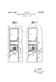
- Fig. 1 shows a sectionthrou h aportion of a window jamb and sash of the type referred to and Fig. 2 represents a similar view of a modified form.
- the numeral 2 represents the indoors portion of the inner jamb wall which is bent outwardly as shown at 4: to
- a baflle8 which also forms a part of the inner jamb. wall.
- a sash plate 10 Extending into the space between members 2 and 8 is a sash plate 10 which is here intended to be a part of the 1930. Serial N0. 453,920.
- Hooked in back of baffle 8 is a member 14 made of flexible material so shaped that it is tensionecl toward the rear face of bafiie 8 near the opening between the-members 2 and 8. .Member 14 ordinarily is made to extend the height of the sash.
- member 16 is hooked over the end 1 the drawing to.v form a columnar space or the column of felt;
- FIG. 2 represents a modified form of the "structure shown in, Figure '1.
- a U-shaped 'member 11 is slipped'over the edge of the sash plate 10 in a close fitting manner.
- Member 11 moves vertically with sash plate 10, but may move horizontally relative thereto and, for the purposes of this application, can be considered a portion of the sash plate 10.
- a member such as 11 is advantageously interposed, being constructed of zinc or other dissimilar metal in order to prevent binding, as pointed out in Campbell application, Se rial No. 383,190.
- a member 17 makes a seal between memner as member 16 seals the sash plate and the for said sash members and felt filling said enlarged spaces.
- a baffle forming part of the inner jamb wall between such openings, separate enlarged chambers back of such openings and sashes having members adapted to extend through such openings sea lin members within the jambs carried by the sash'members movable horizontally but not vertically relative. to the sashmembers adapted to contact with jamb members and each adapted to contact with a-sash member within the jamb at two points on the outdoor side of such sash member and to form an enlarged'space adjacent such sash member between su h points of cont-act, and felt filling aid enlarged space.
- member 11 may be described as a part of the sash plate.
- the felt column has novertical movement relative to the sash member projecting into the jamb, which it seals, and little or no horizontal movement relative thereto, andso is subjected to a negligible amount of wear.
- a baflle forming part of the inner jamb wall between such openings and sashes having plates adapted to extend through such openings, sealmg members movable horizontally but not vertically relative to the sash plates carried by the sash plates within the jambs, each forming an enlarged space upon one side of its sash place, each such sealing member being adapted to contact with a jamb member adjacent'the opening for said sash plates, and absorbent filling Within said enlarged space.
- sash members carried by the sash members within the jambs forming enlarged spaces with the sash members, said enlarged spaces being on one side of said sash members said sealing members being adapted to contact with jamb members adjacent the openings ics 'iio
Landscapes
- Engineering & Computer Science (AREA)
- Civil Engineering (AREA)
- Structural Engineering (AREA)
- Specific Sealing Or Ventilating Devices For Doors And Windows (AREA)
Description
April 12, 1932. H. BIANCO 1,853,845
ABSORBENT WEATHER STRIPPING FOR WINDOWS I Filed May 20, 1930 I N ENTOR ATTORNEY) Patented A r. 12; 1932 UNITED. TATES PATENT; F1;C"E:-.
HENnYBIANco, or B LrIMoR ARYnAivn, AssIGNon ro- CAMBBELL M T L wmnow CORPORATION, or- BALTIMORE, MARYLAND, ACORPORATION OFIIVIARYLAND ABsoRBnNT' wEA'rHEasTnIPPINe FOR wmnows nppliati n filed May 20,
This invention'relates to weather'seals for windows of the type inwhich the jambs have vertical openings through their lnner face .which lead to enlarged ohamberswithin the jambs and the sashes have plates which extendinto these openings, and mvolves a mod1- fication of or improvement upon the construction shown in Campbell Patent No. 1,67 3,393, issued June 12, 1928. With windows of this type it is customary toconstruct the s1ll so that there is an approximately vertical portion or break in the sill about in line with the inside edge of the vertical opening provided for the lower sash. On the room side of such break the sill is ordinarily substantially flat, and at such break the sill drops downwardly so that the lower sash extends down outside of such break. A detailed showing of a sill construction in which this break is particularly apparent is found in Campbell application, Ser. No. 375,384, filed July 2, 1929.
Where the window is exposed to heavy.
' wind pressures as in modern high buildings,
there is danger, in the event of a driving rain storm, that water will be drlven around the ends of the lower sash plates and run to the flat portion of the sill which extends into the jamb, and then leak through into the room. By my present invention lprovlde a construction which overcomes this clifliculty. Inasmuch as the construction is primarily intended for the lower sash of the window, I have illustrated it only in this connection, but
it may also be used in connection with the.
upper sash if occasion should demand.
, My invention may be readily understoodby reference to the accompanying drawings in which Fig. 1 shows a sectionthrou h aportion of a window jamb and sash of the type referred to and Fig. 2 represents a similar view of a modified form. r
In these drawings the numeral 2 represents the indoors portion of the inner jamb wall which is bent outwardly as shown at 4: to
contact with the partition member 6 in the. jamb. Attached to the partition member 6' a is a baflle8 which also forms a part of the inner jamb. wall. Extending into the space between members 2 and 8 is a sash plate 10 which is here intended to be a part of the 1930. Serial N0. 453,920.
lowersash. The line 12 indicates the break of the sill. This is not shown in detail asit forms no part of my present invention.
Hooked in back of baffle 8 is a member 14 made of flexible material so shaped that it is tensionecl toward the rear face of bafiie 8 near the opening between the- members 2 and 8. .Member 14 ordinarily is made to extend the height of the sash.
of the sash plate 10 and is bent as shown in In Fig. 1, member 16 is hooked over the end 1 the drawing to.v form a columnar space or the column of felt;
With this construction if rain is driven by a highwind againstjthe sash and tries to leak into the jamb,'it must follow either one If it forces 1 the extending of two courses. portion of member 16 away .from the rearof ;the baffle 8, it cannot getaround the sash plate 10 for members 16 and 14 will be in spring contact {and if the water follows along the face of the sash between the sash andgmember 1 6, it strikes the absorbent mathe column of felt to the window sill outside of'the sashplate '10 and outside of the break 12 of the sill. v I
- Figure 2 represents a modified form of the "structure shown in, Figure '1. A U-shaped 'member 11 is slipped'over the edge of the sash plate 10 in a close fitting manner. The
'arms' of the U-shapedmember; are long enough .to oover the portion of the sash plate that entersthe jamb and should extendfor an appreciable distance, in close contact with the sash plate, outwardly from thepoint at.
in space 18 in such quantityas will. insure ,a good contact between sash plate 10'and 'teria-l in space/18, and seeps down through which the latter enters the jamb. Member 11 moves vertically with sash plate 10, but may move horizontally relative thereto and, for the purposes of this application, can be considered a portion of the sash plate 10. Where the sash plate and jamb are constructed of a similar metal such as aluminum, a member such as 11 is advantageously interposed, being constructed of zinc or other dissimilar metal in order to prevent binding, as pointed out in Campbell application, Se rial No. 383,190.
The length of the arms of the U-shaped member 11 and their close embracing of the sash plate 10, together with the fact that the arms of the member extend Well beyond the jamb opening, prevent any substantial leakage between member 11 and sash plate 10. A member 17 makes a seal between memner as member 16 seals the sash plate and the for said sash members and felt filling said enlarged spaces.
3. In a Window of the type having ambs, openings through the inner Walls of the jambs, a baffle forming part of the inner jamb wall between such openings, separate enlarged chambers back of such openings and sashes having members adapted to extend through such openings sea lin members within the jambs carried by the sash'members movable horizontally but not vertically relative. to the sashmembers adapted to contact with jamb members and each adapted to contact with a-sash member within the jamb at two points on the outdoor side of such sash member and to form an enlarged'space adjacent such sash member between su h points of cont-act, and felt filling aid enlarged space.
BY BIANCO.
jamb member as represented in Fig. 1, and
therefore, for the purposes of this application, member 11 may be described as a part of the sash plate.
W'ith structures as shown in Fig. 1 and Fig. 2, the felt column has novertical movement relative to the sash member projecting into the jamb, which it seals, and little or no horizontal movement relative thereto, andso is subjected to a negligible amount of wear.
It is to be understood that the foregoing examples are merely illustrative of the embodiment of my invention and are not to be used in limiting the same.
WhatI claim is:
1. In a window of the type having ambs, openings through the inner walls of the jambs, a baflle forming part of the inner jamb wall between such openings and sashes having plates adapted to extend through such openings, sealmg members movable horizontally but not vertically relative to the sash plates carried by the sash plates within the jambs, each forming an enlarged space upon one side of its sash place, each such sealing member being adapted to contact with a jamb member adjacent'the opening for said sash plates, and absorbent filling Within said enlarged space.
sash members carried by the sash members within the jambs forming enlarged spaces with the sash members, said enlarged spaces being on one side of said sash members said sealing members being adapted to contact with jamb members adjacent the openings ics 'iio
Priority Applications (1)
| Application Number | Priority Date | Filing Date | Title |
|---|---|---|---|
| US453920A US1853845A (en) | 1930-05-20 | 1930-05-20 | Absorbent weather stripping for windows |
Applications Claiming Priority (1)
| Application Number | Priority Date | Filing Date | Title |
|---|---|---|---|
| US453920A US1853845A (en) | 1930-05-20 | 1930-05-20 | Absorbent weather stripping for windows |
Publications (1)
| Publication Number | Publication Date |
|---|---|
| US1853845A true US1853845A (en) | 1932-04-12 |
Family
ID=23802583
Family Applications (1)
| Application Number | Title | Priority Date | Filing Date |
|---|---|---|---|
| US453920A Expired - Lifetime US1853845A (en) | 1930-05-20 | 1930-05-20 | Absorbent weather stripping for windows |
Country Status (1)
| Country | Link |
|---|---|
| US (1) | US1853845A (en) |
-
1930
- 1930-05-20 US US453920A patent/US1853845A/en not_active Expired - Lifetime
Similar Documents
| Publication | Publication Date | Title |
|---|---|---|
| US9556668B2 (en) | Weather seal system for double hung windows | |
| US2303129A (en) | Window construction | |
| US4044504A (en) | Sash window with weathertight sealing means | |
| US1853845A (en) | Absorbent weather stripping for windows | |
| US3248822A (en) | Sliding closure construction | |
| US1796242A (en) | Casement window | |
| US2120614A (en) | Metal double hung window | |
| KR20200132063A (en) | Sliding windows having windbreak structure of check rails for auxiliary rail | |
| KR101583722B1 (en) | Multi rail windows improved airtight performance | |
| US1826686A (en) | Weather seal construction for windows | |
| KR102716417B1 (en) | Miseogi window for preventing inflow of seawater and rainwater with insulation function | |
| KR102351034B1 (en) | Glazed window with improved watertightness | |
| US1644814A (en) | Double-hung window | |
| KR20170052197A (en) | an air protection confidential structure for window | |
| US1518374A (en) | Window sash | |
| US2065078A (en) | Weather strip | |
| US1887415A (en) | Casement window | |
| US1606073A (en) | hebberd | |
| US1751720A (en) | Weather strip for casement sashes | |
| US2289558A (en) | Building construction | |
| US1247377A (en) | Weather-strip. | |
| US1823237A (en) | Vehicle storm sash | |
| US1827222A (en) | Window head construction | |
| US978624A (en) | Window-screen. | |
| US783936A (en) | Combined window-screen and weather-strip. |