US1853844A - Reclining seat - Google Patents
Reclining seat Download PDFInfo
- Publication number
- US1853844A US1853844A US385111A US38511129A US1853844A US 1853844 A US1853844 A US 1853844A US 385111 A US385111 A US 385111A US 38511129 A US38511129 A US 38511129A US 1853844 A US1853844 A US 1853844A
- Authority
- US
- United States
- Prior art keywords
- seat
- rack
- guide
- back rest
- reclining
- Prior art date
- Legal status (The legal status is an assumption and is not a legal conclusion. Google has not performed a legal analysis and makes no representation as to the accuracy of the status listed.)
- Expired - Lifetime
Links
- 238000010276 construction Methods 0.000 description 7
- 230000006835 compression Effects 0.000 description 4
- 238000007906 compression Methods 0.000 description 4
- NJPPVKZQTLUDBO-UHFFFAOYSA-N novaluron Chemical compound C1=C(Cl)C(OC(F)(F)C(OC(F)(F)F)F)=CC=C1NC(=O)NC(=O)C1=C(F)C=CC=C1F NJPPVKZQTLUDBO-UHFFFAOYSA-N 0.000 description 2
- 230000000149 penetrating effect Effects 0.000 description 2
- RYGMFSIKBFXOCR-UHFFFAOYSA-N Copper Chemical compound [Cu] RYGMFSIKBFXOCR-UHFFFAOYSA-N 0.000 description 1
- 102100026933 Myelin-associated neurite-outgrowth inhibitor Human genes 0.000 description 1
- 230000004308 accommodation Effects 0.000 description 1
- 238000004140 cleaning Methods 0.000 description 1
- 239000000428 dust Substances 0.000 description 1
- 230000002045 lasting effect Effects 0.000 description 1
- 230000000670 limiting effect Effects 0.000 description 1
- 238000009877 rendering Methods 0.000 description 1
- 230000000717 retained effect Effects 0.000 description 1
- 239000007787 solid Substances 0.000 description 1
Images

Classifications
-
- B—PERFORMING OPERATIONS; TRANSPORTING
- B61—RAILWAYS
- B61D—BODY DETAILS OR KINDS OF RAILWAY VEHICLES
- B61D33/00—Seats
- B61D33/0007—Details; Accessories
- B61D33/0014—Seat frames
- B61D33/0021—Seat frames for adjustable or reclining seats
Definitions
- This invention relates to reclining seats
- seats for use in- .railway coaches, busses and tramcars, havattractive to the public requires that the seats l be made as comfortable and convenient as possible.
- the passenger becomes weary if required to sit in a certain definite position throughout the length of the journey.
- a vehicle seat can be made very much more comfortable and restful if the back rest can be variously reclind in a variety of positions, as the passenger desires, so that he is not compelled to sit in one fixed position throughout the journey.
- the operative element for reclining the back rest should be convenientlg located and easily manipulated,so that the ack rest can be reclined in a variety of positionswith the least effort on the part of the passenger, and can be quickly and conveniently restored to upright position by the passenger or trainman.
- a principal object of this invention is to provide a reclining seat which 1s free of the objections noted above, and, therefore, especially well suited for use in rallway or tramcars or in automotive busses.
- a further object of this invention is to provide a seat having a hinged back rest adapted to be adjustably reclined in a vari'ety of reclining positions, in a 'simple and convenient manner requ1r1ng a minimum of effort, and provlded w1th means for adjustably retaining the back rest-in any one of a number of inclined positions.
- Another object of this invention is to provide reclining mechanism for reclining seats, which is simple and light in construction, which is easytoymanipul'ate, and which is strong and lasting in service, and will withstand great abuse without getting out of order.
- the seat back is hinged at its lower edge to a suitable support.
- the reclining mechanism may include a rack member pivotally secured to the lower iedge of the ba'ck rest below the hinge, and extending underneath the seat cushion or seating portion of the seat.
- Mechanism, positioned under the seat cushion or beneath the seating portion of the seat, is engageable with the rack member at different points to ive the desired adjusted inclination to the seat back, this mechanism being readily disengageable from the rack members by the passenger or by trainmen to permit the inclination of the seat back to be altered.
- Means are also' preferably provided Vwhich act to return the seat back to upright position when released, these means being also positioned beneath the seat cushion or seating portion of the seat.
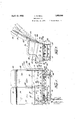
- Figure 1 is a front elevational view of a.I double vehicle seat having myl novel reclining mechanism associated wit a hinged back rest;
- Figure 2 is an end view of my seat showing t e reclining mechanism operative? connected to the hinged back rest, dotte being used to indicate various inclined positions which the back rest may assume;
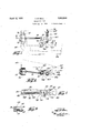
- Figure 3 is an enlarged top view ofmy novel reclining mechanism, certain parts be- ⁇ ing broken away to more clearly show the construction, the view being taken on line 3-3 of Figure 2;
- Figure 4 is an enlarged fragmentary crosssectional view of a portion of my reclining mechanism, the view being taken on line 4--4 of Figure 3
- Figure 5 is an enlarged fragmentary cross! sectional view of another portion of my reclining mechanism, taken on line 5-5 of Figure 3;
- Figure 6 is a front view of my reclining mechanism, a portion of the seat cushion structure being shown in dotted lines;
- Figure 7 is a fragmentary top view of a modi ed construction of my reclining mechanism, showing more particularly a modiied manipulating element
- Figure 8 is a sectional view of the same, and is taken on the line 8--8 of Figure 7, and Fi re 9 is an enlarged fragmentary view of a ightly modified construction of my reclinin mechanism.
- -I ⁇ have shown my back reclining mechanism associated with' adouble vehicle seat having a pair of individual seat cushions and a pair of individual reclining' back rests. It will be understood, however, that I contemplate using my seat back tilting mechanism with an type of seat and do not limit myself to double seats, or seats for vehicle use. For urposes of i1- lustration only therefore, I s ow a double seat having a seat frame 10 supported on any suitable pedestal. I have shown for purposes l of illustration only a supporting pedestal comprising corner posts 11 connected together in a solid manner by means of horizontal rails 12.
- each post may be provided with a foot portion 13 through which any suitable securing means (not shown) may extend to ixedly secure the seat Ito the floor.
- the top of each post may be similarly provided wit a ca portion 14 forming a supporting surface or the seat frame 10.
- -A spring assembly 15 may be supported on the frame'10.
- a face plate 16 extending across the front of the supporting frame and around the front corners thereof vmay be provided to retain the spring assembly 15 in proper position.
- Individual seat cushions 17 may be supported directly on the spring assembly 15.
- the top of each spring assembly may be in lines ⁇ n inermediate su cli'ned rearwardl as shown in Figure, to give a comfortabl e inclination to the seat cushions supported thereon.
- the back rest portion of the seat may be of any suitable construction.
- the back rest portions are pivotally mounted on suitable supports extending upwardly from the frame 10 of the seat.
- Arm rest 20 of the seat may comprise one of these supporting members.
- the arm rest 20 is firmly secured in any suitable manner to the frame 10.
- the top edge periphery 21- and the front edge periphery 22 ma be suitably .shaped so as to present a com ortable supporting surface for the arm of the passenger.
- An elongated bar member 25 is suitably secured, as by means of screws 25', to each side edge of the respective back rest portions.
- stud element 26 prcjects'laterallyxfrom the respective supporting members 20, 23 and 24 above described to pivotally support the back rest portions.
- Each stud element may be provided with a base portion 27 p through which suitablesecuring elements may extend to firmly fix the stud in proper position on its supporting member.
- a pair of stud elements are provided for each back rest portion, each stud element extending through a journal aperture in the corresponding bar member 25, thuspivotaL ly supporting the back rest portion to permit the same to swing forward and backward.
- ay pair of bar members 25 are provided for each back rest por tion, one being disposed at each side edge of the same.
- Each bar member is provided with a downwardly projecting extension 28 that extends below the pivot point of the back rest portion, as clearly shown in Figure 2.
- My reclining mechanism is operatively connected to the free en d of each pair of projecting extensions 28 of the bar members.
- guide block generally com risesa'fbase I' a rounded support 38 connecting the* ⁇ lower ends of the spaced guide portions 36 and 37.
- Suitable securing elements may extend through the baseuportion ofthe guide block and into the seat'frame 19, firmly securing the ide block 'm position.
- Alidck bolt 39 is providedwhich is adapted i to selectivelyengage with the spaced apertures 34 .provided in the stem portion 33 of therack member.
- the lock bolt' is preferably :1,39
- f e locking end of the lock bolt may be roundedso'as to more easily direct itself into the spacedvapertures rovided in the stem portion ofthe rack mem r.'
- the spaced apertures in the ⁇ stem portionv .of the l. rack member may also be reamed, as at'42, to facilitate the entrance ⁇ v ⁇ vof the-locking end of' 'the lock boltintothe'res ctive apertures.
- the lookin end of the loc bolt is not completely wit drawn from theaperture 40 in guide dportion 36, when the lock bolt is re. tracte Guide portion 36 thus 'forms a permanent support for the locking end of the lock bolt, and is therefore considerably 'thicker than the guide portion37, as clear] shown in ' Figure 3.
- the other end of the loc bolt is supported imposition by means of a guide block comprisin a base rtion 43 and a downwardly exten 1n gui e portion 44.
- the lock bolt extends t rough an aperture provided in the guideportion 44, and isvfree to reciprocate therein.
- Expansion spring 45 operates to normally shoot the lock bolt forwardly through the se-V lected aperture in the stem portion 33 of the rack member, and aperture 41 in guide portion 37.'-
- lock bolt 39 can be moved out of engagement wi the stem portion 33 of the rack member.
- manipulating element may comprise an opo "facilitate rotation of the operating s1- ⁇ ing bolt is moved out of engagementwith the rack member against the action of ex.
- pansible coilisflng 46 pansible coilisflng 46. ⁇ The back rest vpor- ⁇ tion can then adjusted to any reclining4 osition desired. As soon as the manipulatin 1everis'released,'the coil spring 46 will v vswing the lever back to normal at rest osition and project the end lof the latch bolt into the stem portion of the rack member.
- Driving'means are provided for swinging the back rest portion forwardly when the lock bolt is disengaged from the stem portion of the' rack member and/or body pressure is removed from the back rest end I provideA a ⁇ wall portion 56 projecting 12o ortion. To this l laterallyfrom the free end of the stem portion 33 of the rack member. An aperture is provided in the wall portion 56 through which a guide rod 57 is free to slide.
- a guide rod is supported in position by means of a bracket comprising a base portion 58 and a pair of downwardly extending spaced l lug portions 59.
- knuckle member 60 may be of the form shown -in ⁇ Figure 5 with the expanding pressure of "u coil s ring 62 exerted directly against thel pivot 1t 61, 0r. of the form shown in Figure 'v 9 with the expanding pressure from coil sp 62 exerted to one side ofthe pivotbolt Lrm'Ihe pressure exerted by the coil spring o 62 tends to push the rack member rearwardly and swing the back rest portion of the seat forwa y.
- coil spring 62 will operate to swing thejv back restportion forwardly to a more nearly 'vertical position.
- k go I provide a stop pin 63 which extends through ⁇ the stem portion of-the rack memberand vis adapted to abut against lug portions 36 and 37 when the backrest portionis swung for- .ward a predetermined amount.
- the lock bolt 39 extends between I the spaced fingers 68 and is ⁇ pivotally con- ⁇ nected thereto by means of a pivotbolt 69, v which extends t rough the end of the lock vbolt and seats within a recess 'cut in-the end .in Aof each finger portion 68.
- the other arm 70 of the bell crank lever is pivotally connected as by means of a pivot bolt 71 to an operating rod 72.
- the operating lrod 72 ex- Atends'as before from the vicinity of the lockg5. bolt ⁇ to the front edge of the seat.
- a bracket member having-an attaching portion 73 and a cup shaped body portion 74' is positioned vat Va convenient point. along the front' edgeyof the seat'.
- The'outer end of the operating rod fr 72 extends through an aperture inthe body rtion 74 of. the bracket.
- a manipulating ead 75 telescoping withinthe cup shaied body portion 74 of the bracket is secure to the outer end of the operating rod. It is now 3 5/seen by exerting pressure on the ⁇ manipuf e outer end-of the guide lrodl'lif isv combination.
- the seatcushion is inclined at a comfortable angle and-the back rest can 'is -be positioned in a variety 'oinclined positions.
- the occupant 'of the .seat is, thereg fore, not forced to maintaina certain .sitting position on -long journeys, b ut may variously recline himself on th ⁇ e ⁇ 'seat to maintain maximum comfort.
- the mechanism comprises few partsangl attached to the undersideof the seat. framelO as to occupy very little space.
- the operatin mechanism is out o f the way and oersfpo o ruction to the cleaning of thenfiqoigfjunder the seat.
- the lwhole is so compactlys'sembled vas to permit. the parts to be lrotected within 4a suitable cover ('notshown ifl such is founddesirable.
- the manipulatinglever or push button by means of which the occupantltiltsthe back rest is conveniently arranged along the front .a5 edge of the seat sothatthe passenger is able to tilt the back rest scarcely without effort.
- the tilting mechanism is made of few arts, sturdily constructed ,and easy .to assemble.
- amanually operable device adapted to be releasably engaged ⁇ Withsaid rack bar to hold the seat back inadjusted position of inclination, and means including a vcoilspring'encircling said guide rod and pressing against said rack bar abutment, to restore the seat back, when released, to elevated position.
- supporting structure a seat back pivotally mounted thereon and having a depending extension, a rack bar support and guide' member mounted on the supportng structure, a rack bar pivotally anchored at one end to the back extension and at the other end slidablv supported and guided by said guide mem er and provided with an abutment having an aperture, a guide rod y )ivotally anchored at one end to the sup-v porting structureand havin Aits other end slidably penetrating said a utment aperture, a manually operable device adapted to be releasably engaged with said rack bar to hold the seat back in adjusted position of inclination, and means including a coil spring encircling said guide rod and pressing against said rack bar abutment, to restore the seat back, when released, to elevated position,l said latch device including a latch pin vhaving its rack bar engaging end slidably retained and guidedA in the rack bar support and guide member.
- a seat having a frame and a seat back adjustably supported thereon, in combination, a rack member secured to the seat back, a guide member therefor secured to the seat frame, a compression spring supporting member having one end swingingly connected to the seat frame andthe other end swingingly connected to the rack member, a
- tent means for retaining the rack member and seat back in adjusted position, a com-- pression spring supporting member, a compression spring supportedy thereby, said rack 5o member having an abutment engaging one end of said spring and swingingly supporting one end of the spring supporting mem. ber, the other end of said spring supporting member being swingingly secured to the seat frame and having an abutment engaging the other end of said spring, the spring bem compressed between said abutments w ereby said spring normally tends to force the rack member rearwardly to elevate the du seat back.
Landscapes
- Engineering & Computer Science (AREA)
- Mechanical Engineering (AREA)
- Seats For Vehicles (AREA)
Description
April 12, 1932. A. B. BELL REGLINING SEAT Filed Aug. 12, 1929 3 Sheets-Sheet Il NUE:
N %m. LJ ln.
MN V NQ .rhN Wxltr. .0N n 1 AN April l2, 1932.
A. B. BELL V RECLINING SEAT 3 Sheets-Sheet 2 Filed Aug. l2, 1929 'ff/Imaz .mln
INVENTOR I l Y-/IQJQ A. BELL REGLINING SEAT April 12,1932.
Filedv Aug. 12, 1929 3 Sheets-Shea?l 3 INVENTOR @da M Patented Apr. 12, 1932 .UNITED s'ra'rlizsy PATENT OFFICE ALFRED B. BELL, OF PHILADELPHIA, PENNSYLVANIA, ASSIGNOR TO HALE & KIL- BURN CO., OF PHILADELPHIA, PENNSYLVANIA, A CORPORATION OF DELAWARE RECLINING SEAT Application `1ed August 12, 1929. Serial No. 385,111.
This invention relates to reclining seats,
and more particularly to seats for use in- .railway coaches, busses and tramcars, havattractive to the public requires that the seats l be made as comfortable and convenient as possible. In long distance transportation, the passenger becomes weary if required to sit in a certain definite position throughout the length of the journey. A vehicle seat can be made very much more comfortable and restful if the back rest can be variously reclind in a variety of positions, as the passenger desires, so that he is not compelled to sit in one fixed position throughout the journey. To further increase the comfort of the passenger, the operative element for reclining the back rest should be convenientlg located and easily manipulated,so that the ack rest can be reclined in a variety of positionswith the least effort on the part of the passenger, and can be quickly and conveniently restored to upright position by the passenger or trainman. V
The provision of seats having backs which may be adjusted to differenty inclinations is not broadly novel. However, reclining seats have been used to a very small extent for passenger transportation, for instance, in
` railway or tramcars o-r automotive busses because of various objectionable features. For instance, it is of utmost advantage, especially in interurban service, to provide as many seats as possible in each car or bus. Heretofore reclining seats have required a large amount of space and have not been suitable vfor such use on account of the consequenteduction in the seating accommodations of the car or bus. Further, the reclining mechanism heretofore used occupied considerable space under the seat, rendering it diflicult to Ico clean under the seat. Reclining devices heretofore used have also been heavy, cumbersome, and difficult to operate. A further objection has been that much of the reclining mechanism is exposed and often interferes with passengers entering or leaving the seats.
Accordingly, a principal object of this invention is to provide a reclining seat which 1s free of the objections noted above, and, therefore, especially well suited for use in rallway or tramcars or in automotive busses.
A further object of this invention is to provide a seat having a hinged back rest adapted to be adjustably reclined in a vari'ety of reclining positions, in a 'simple and convenient manner requ1r1ng a minimum of effort, and provlded w1th means for adjustably retaining the back rest-in any one of a number of inclined positions.
Another object of this invention is to provide reclining mechanism for reclining seats, which is simple and light in construction, which is easytoymanipul'ate, and which is strong and lasting in service, and will withstand great abuse without getting out of order.
Other objects of' this invention will become evident as the disclosure proceeds.
In accordance with my invention, the seat back is hinged at its lower edge to a suitable support. The reclining mechanism may include a rack member pivotally secured to the lower iedge of the ba'ck rest below the hinge, and extending underneath the seat cushion or seating portion of the seat. Mechanism, positioned under the seat cushion or beneath the seating portion of the seat, is engageable with the rack member at different points to ive the desired adjusted inclination to the seat back, this mechanism being readily disengageable from the rack members by the passenger or by trainmen to permit the inclination of the seat back to be altered. Means are also' preferably provided Vwhich act to return the seat back to upright position when released, these means being also positioned beneath the seat cushion or seating portion of the seat.
In order that a clearer understanding of my invention may be had, attention is hereby directed to the accompanyingdrawings, forming a part/of this application and illustrating certain possible embodiments of my invention.
Referring to the drawings, Figure 1 is a front elevational view of a.I double vehicle seat having myl novel reclining mechanism associated wit a hinged back rest;
Figure 2 is an end view of my seat showing t e reclining mechanism operative? connected to the hinged back rest, dotte being used to indicate various inclined positions which the back rest may assume;
Figure 3 is an enlarged top view ofmy novel reclining mechanism, certain parts be- `ing broken away to more clearly show the construction, the view being taken on line 3-3 of Figure 2;
Figure 4 is an enlarged fragmentary crosssectional view of a portion of my reclining mechanism, the view being taken on line 4--4 of Figure 3 Figure 5 is an enlarged fragmentary cross! sectional view of another portion of my reclining mechanism, taken on line 5-5 of Figure 3;
Figure 6 is a front view of my reclining mechanism, a portion of the seat cushion structure being shown in dotted lines;
Figure 7 is a fragmentary top view of a modi ed construction of my reclining mechanism, showing more particularly a modiied manipulating element;
Figure 8 is a sectional view of the same, and is taken on the line 8--8 of Figure 7, and Fi re 9 is an enlarged fragmentary view of a ightly modified construction of my reclinin mechanism.
i imilar reference characters refer to similar parts throughout the several views of the drawings.
Referring to the drawings, -I\ have shown my back reclining mechanism associated with' adouble vehicle seat having a pair of individual seat cushions and a pair of individual reclining' back rests. It will be understood, however, that I contemplate using my seat back tilting mechanism with an type of seat and do not limit myself to double seats, or seats for vehicle use. For urposes of i1- lustration only therefore, I s ow a double seat having a seat frame 10 supported on any suitable pedestal. I have shown for purposes l of illustration only a supporting pedestal comprising corner posts 11 connected together in a solid manner by means of horizontal rails 12. rIhe lower end of each post may be provided with a foot portion 13 through which any suitable securing means (not shown) may extend to ixedly secure the seat Ito the floor. The top of each post may be similarly provided wit a ca portion 14 forming a supporting surface or the seat frame 10. -A spring assembly 15 may be supported on the frame'10. A face plate 16 extending across the front of the supporting frame and around the front corners thereof vmay be provided to retain the spring assembly 15 in proper position. Individual seat cushions 17 may be supported directly on the spring assembly 15. The top of each spring assembly may be in lines `n inermediate su cli'ned rearwardl as shown in Figure, to give a comfortabl e inclination to the seat cushions supported thereon.
The back rest portion of the seat may be of any suitable construction. To insure the greatest ossible seating comfort, however, I preferab y construct m back rest portion so as to present a comfor ably cushioned body supporting section 18, and a head rest section 19, each section being sha ed so as to respectively conform, to the bo y and head of the passenger.
The back rest portions are pivotally mounted on suitable supports extending upwardly from the frame 10 of the seat. Arm rest 20 of the seat may comprise one of these supporting members. The arm rest 20 is firmly secured in any suitable manner to the frame 10. The top edge periphery 21- and the front edge periphery 22 ma be suitably .shaped so as to present a com ortable supporting surface for the arm of the passenger.
shown in dotted lines in Figure 1, and positioned midway between the seat ends, is secured in an upright manner to the seat frame 10. Intermediate supportiig member 23 supports the adjacent inner e ges of the back restl portions in a manner presently to be described. The wall side edge of the inner back rest portion 18 may also be supported by means of a suitable upright su porting member 24 firmly fixed to the seat rame 10.
An elongated bar member 25 is suitably secured, as by means of screws 25', to each side edge of the respective back rest portions.
'As shown in Figure 1, ay pair of bar members 25 are provided for each back rest por tion, one being disposed at each side edge of the same. Each bar member is provided with a downwardly projecting extension 28 that extends below the pivot point of the back rest portion, as clearly shown in Figure 2.
My reclining mechanism is operatively connected to the free en d of each pair of projecting extensions 28 of the bar members.
' Referring more particularly to Figures 3 and porting member 23h l vo'tall to- `the lower l,e1-id of: onel of the ownwardly projecting extensions 28 of bar member by means.y of a pivot bolt 3 0 fixed-v ly in tion h any suitable means such as a w erA 31 an va cotter pinv 32 extendin through the bolt. `The stemportion 33 ofv t e Y-'shaped rack member is provided l 'with a lurality'of spaced apertures34 with which. f'eelocking'mechanismuis adaptedfto selectively "engage The stem member supported gclnlsiton by means of a suitable guide-block.
guide block generally com risesa'fbase I' a rounded support 38 connecting the*` lower ends of the spaced guide portions 36 and 37. Suitable securing elements (not shown) may extend through the baseuportion ofthe guide block and into the seat'frame 19, firmly securing the ide block 'm position. The `lower ed of t e stem portion of .the Arack member sides over on the rounded supporting rtion of the guide block.v 4,' l
positioned at right angles to the stem portion 330i the'rack member, and is adapted to slide "within'alindapertures 4 0` and 41 in the res ective uide portions 36 and 37 ofthe guide b ock. f e locking end of the lock bolt may be roundedso'as to more easily direct itself into the spacedvapertures rovided in the stem portion ofthe rack mem r.' The spaced apertures in the` stem portionv .of the l. rack member may also be reamed, as at'42, to facilitate the entrance `v` vof the-locking end of' 'the lock boltintothe'res ctive apertures.
The lookin end of the loc bolt is not completely wit drawn from theaperture 40 in guide dportion 36, when the lock bolt is re. tracte Guide portion 36 thus 'forms a permanent support for the locking end of the lock bolt, and is therefore considerably 'thicker than the guide portion37, as clear] shown in 'Figure 3. The other end of the loc bolt is supported imposition by means of a guide block comprisin a base rtion 43 and a downwardly exten 1n gui e portion 44. The lock bolt extends t rough an aperture provided in the guideportion 44, and isvfree to reciprocate therein.
is secured tothe lock bolt, as shown in Figure 3. An expansible A collar member .45
' coil spring 46 surrounds the lock bolt and ispositioned between the ycollar 45 and the vgui/deI portion 44 of the supporting block.
ortion'35, and a pair of space downward. i) extending guidev portions 36 and 37. The stem portionof the r-ack member restsupon i: Means are stem eratin rod 47extending ront edge of the seat -isprovided with portion `of the-rack member. An o i to the -a'rocking withja v:forked portion comprising a vpair of arms 49 spaced apart, as shown in Figure 4. l' The en d of the lock bolt extends between the arms of the forked portion andy is vpivotall g connected thereto by means of a suitable bo t 50. extending throulll the-'lock bolt 39 and` f' `the two arms 49 of e lforked portion. 'The operating rod 47 lis'su ported at the outer l:end thereof by means o a bracket having an vattaching portion 5l and a downwardly ex-r tending flanged portion 5 2. The front end for manually retract-y ingthe lock bolt out ofengagement with the den the lock be 51F; element 48 ixedtothe inner end thereoth'y The rocking element is provided 'of the operating rod is journalled in a suitable-'journal aperture inthe anged portion 52. `-The inner end of the voperating rod extendsrthrough .a journal. aperture rovided in a flanged extension 53 ro'ecting guide portion 48, as clear s v 3 and 4. Now it is seen that by rotating the operating rod 47 in a clockwise direction, the
om the own 1n Figures .90. i
lock bolt 39 can be moved out of engagement wi the stem portion 33 of the rack member.
rod, I provide a mani ulating element tioned at'the front e ge of the seat. his
"manipulating element may comprise an opo "facilitate rotation of the operating s1-` ing bolt is moved out of engagementwith the rack member against the action of ex.
Driving'means are provided for swinging the back rest portion forwardly when the lock bolt is disengaged from the stem portion of the' rack member and/or body pressure is removed from the back rest end I provideA a `wall portion 56 projecting 12o ortion. To this l laterallyfrom the free end of the stem portion 33 of the rack member. An aperture is provided in the wall portion 56 through which a guide rod 57 is free to slide. The
guide rod is supported in position by means of a bracket comprising a base portion 58 and a pair of downwardly extending spaced l lug portions 59. Suitable securing means `pansi le coil' spring 62,. surrounding the- -guide rod and positioned between the wall .lo portion 56 and the knuckle member 60 op erates to exertvpressurecnl the wall portion"r "56. connected to the rack/memben The..4
' 35 As a` modified construction, I have shown.` in Figures 7 and 8 a different arrangement.' for manipulating the lock bolt. In thiscon- 'struction I provide a` bracket having a base Y i portion 64 and a downwardly extending stud o portion 65. A bell crank lever is pivotally v mountedfon the stud portion, and secured in place by means of a screw 66. The-outer end of arm 67 ofthe bell crank lever is forked soas to provide a pair of spaced yiin- '5 gers 68. vThe lock bolt 39 extends between I the spaced fingers 68 and is `pivotally con-` nected thereto by means of a pivotbolt 69, v which extends t rough the end of the lock vbolt and seats within a recess 'cut in-the end .in Aof each finger portion 68. The other arm 70 of the bell crank lever is pivotally connected as by means of a pivot bolt 71 to an operating rod 72. The operating lrod 72 ex- Atends'as before from the vicinity of the lockg5. bolt `to the front edge of the seat. A bracket member having-an attaching portion 73 and a cup shaped body portion 74' is positioned vat Va convenient point. along the front' edgeyof the seat'. The'outer end of the operating rod fr 72 extends through an aperture inthe body rtion 74 of. the bracket. A manipulating ead 75 telescoping withinthe cup shaied body portion 74 of the bracket is secure to the outer end of the operating rod. It is now 3 5/seen by exerting pressure on the` manipuf e outer end-of the guide lrodl'lif isv combination.
fthe passenger. ,The seatcushion is inclined at a comfortable angle and-the back rest can 'is -be positioned in a variety 'oinclined positions. The occupant 'of the .seat is, thereg fore, not forced to maintaina certain .sitting position on -long journeys, b ut may variously recline himself on th`e` 'seat to maintain maximum comfort. The mechanism comprises few partsangl attached to the undersideof the seat. framelO as to occupy very little space. The operatin mechanism is out o f the way and oersfpo o ruction to the cleaning of thenfiqoigfjunder the seat. Should' it be desirable toprotect the voperative elements of mechanism from dust 'and' tampering; passengers, the lwhole is so compactlys'sembled vas to permit. the parts to be lrotected within 4a suitable cover ('notshown ifl such is founddesirable. The manipulatinglever or push button by means of which the occupantltiltsthe back rest is conveniently arranged along the front .a5 edge of the seat sothatthe passenger is able to tilt the back rest scarcely without effort. The tilting mechanism is made of few arts, sturdily constructed ,and easy .to assemble.
As many changes c'cnild be made in the .above construction and as-.xmany apparently vwidely different embodiments of this inven tion could be `made'without departing from the scope thereof, it is intended that all mat- 4ter contained'. in the above description or shown in the accompanying drawings shall be interpreted as illustrative and not in a lim- -iting sense.4 f v 1. In a chair of the character described, in
supporting structure, a seat` back pivotally mounted. thereon and having ay depending extension, a rack bar support and guide member mounted on the supportlng structure, a rack bar pivotally anchored .at one end to theback extension and at the Iother end slidably supported and guided by .said guide mem er and provided with4 an abutment having an aperture, a guide rod pivotally anchored at one end to the supporting struct'u re and having its other. end slidably penetrating said abutment aperture. amanually operable device adapted to be releasably engaged `Withsaid rack bar to hold the seat back inadjusted position of inclination, and means including a vcoilspring'encircling said guide rod and pressing against said rack bar abutment, to restore the seat back, when released, to elevated position. v
2. a chair of the character described, 13
ils
in combination. supporting structure, a seat back pivotally mounted thereon and having a depending extension, a rack bar support and guide' member mounted on the supportng structure, a rack bar pivotally anchored at one end to the back extension and at the other end slidablv supported and guided by said guide mem er and provided with an abutment having an aperture, a guide rod y )ivotally anchored at one end to the sup-v porting structureand havin Aits other end slidably penetrating said a utment aperture, a manually operable device adapted to be releasably engaged with said rack bar to hold the seat back in adjusted position of inclination, and means including a coil spring encircling said guide rod and pressing against said rack bar abutment, to restore the seat back, when released, to elevated position,l said latch device including a latch pin vhaving its rack bar engaging end slidably retained and guidedA in the rack bar support and guide member.
3. -In a seat having a frame and a seat back adjustably supported thereon, in combination, a rack member secured to the seat back, a guide member therefor secured to the seat frame, a compression spring supporting member having one end swingingly connected to the seat frame andthe other end swingingly connected to the rack member, a
compression sprin carried by said supporting member, an a utment on said supporting member for one end of the spring and an si vabutment, on the rack bar for the other end of the spring, said spring being compressed between said abutments whereby said spring normally tends to force the rack member rearwardly to elevate the seat back, and releas- 40 able detent means for holding the seat back in-adjusted position.
4. In a seat having a frame and a seat back adjustably Vsupported thereon, in combination, a rack member movablysupported by the frame and connected to the seat back, de-
tent meansfor retaining the rack member and seat back in adjusted position, a com-- pression spring supporting member, a compression spring supportedy thereby, said rack 5o member having an abutment engaging one end of said spring and swingingly supporting one end of the spring supporting mem. ber, the other end of said spring supporting member being swingingly secured to the seat frame and having an abutment engaging the other end of said spring, the spring bem compressed between said abutments w ereby said spring normally tends to force the rack member rearwardly to elevate the du seat back. l
This specification signed this 25th day of July, 1929.
ALFRED B. BELL.
Priority Applications (1)
| Application Number | Priority Date | Filing Date | Title |
|---|---|---|---|
| US385111A US1853844A (en) | 1929-08-12 | 1929-08-12 | Reclining seat |
Applications Claiming Priority (1)
| Application Number | Priority Date | Filing Date | Title |
|---|---|---|---|
| US385111A US1853844A (en) | 1929-08-12 | 1929-08-12 | Reclining seat |
Publications (1)
| Publication Number | Publication Date |
|---|---|
| US1853844A true US1853844A (en) | 1932-04-12 |
Family
ID=23520051
Family Applications (1)
| Application Number | Title | Priority Date | Filing Date |
|---|---|---|---|
| US385111A Expired - Lifetime US1853844A (en) | 1929-08-12 | 1929-08-12 | Reclining seat |
Country Status (1)
| Country | Link |
|---|---|
| US (1) | US1853844A (en) |
Cited By (1)
| Publication number | Priority date | Publication date | Assignee | Title |
|---|---|---|---|---|
| US2770292A (en) * | 1951-09-24 | 1956-11-13 | William S Hamilton | Spring-back chair |
-
1929
- 1929-08-12 US US385111A patent/US1853844A/en not_active Expired - Lifetime
Cited By (1)
| Publication number | Priority date | Publication date | Assignee | Title |
|---|---|---|---|---|
| US2770292A (en) * | 1951-09-24 | 1956-11-13 | William S Hamilton | Spring-back chair |
Similar Documents
| Publication | Publication Date | Title |
|---|---|---|
| US2270172A (en) | Vehicle seat | |
| US3065029A (en) | Headrest construction | |
| US2859797A (en) | Adjustable reclining chair and headrest therefor | |
| US3632161A (en) | Side arm stowable table | |
| US1548334A (en) | Automobile seat bed | |
| US1893458A (en) | Car seat | |
| US2304199A (en) | Adjustable ambulance chair | |
| US1428018A (en) | Automatic folding seat construction | |
| US2085836A (en) | Arm rest for reclining coach seats | |
| US3193326A (en) | Automobile baby seat | |
| US2669284A (en) | Adjustable vehicle seat | |
| US2655197A (en) | Convertible seat | |
| US1853844A (en) | Reclining seat | |
| US1896477A (en) | Back seat for automobiles | |
| US3563604A (en) | Chair assembly having a movable armrest | |
| US1922502A (en) | Aisle seat for busses | |
| USRE17755E (en) | Front-seat construction for automobiles | |
| US2283600A (en) | Footrest | |
| US2555144A (en) | Footrest for reclining seat chairs which is convertible into a table | |
| US2200904A (en) | Revolving car seat | |
| US3088704A (en) | Supplemental seat for vehicles | |
| US2035452A (en) | Aisle seat | |
| US2035451A (en) | Auxiliary seat | |
| US2642922A (en) | Reversible and berthable seat | |
| US2893473A (en) | Jointed arm rest |