US1853820A - Steam heating system - Google Patents
Steam heating system Download PDFInfo
- Publication number
- US1853820A US1853820A US287229A US28722928A US1853820A US 1853820 A US1853820 A US 1853820A US 287229 A US287229 A US 287229A US 28722928 A US28722928 A US 28722928A US 1853820 A US1853820 A US 1853820A
- Authority
- US
- United States
- Prior art keywords
- steam
- pressure
- pipe
- heating
- condensate
- Prior art date
- Legal status (The legal status is an assumption and is not a legal conclusion. Google has not performed a legal analysis and makes no representation as to the accuracy of the status listed.)
- Expired - Lifetime
Links
- 238000010438 heat treatment Methods 0.000 title description 32
- XLYOFNOQVPJJNP-UHFFFAOYSA-N water Substances O XLYOFNOQVPJJNP-UHFFFAOYSA-N 0.000 description 12
- 238000009835 boiling Methods 0.000 description 4
- 230000005494 condensation Effects 0.000 description 4
- 238000009833 condensation Methods 0.000 description 4
- 230000001105 regulatory effect Effects 0.000 description 3
- 238000010276 construction Methods 0.000 description 2
- 238000004326 stimulated echo acquisition mode for imaging Methods 0.000 description 2
- 241000272168 Laridae Species 0.000 description 1
- 230000001276 controlling effect Effects 0.000 description 1
- 239000000463 material Substances 0.000 description 1
- 230000005855 radiation Effects 0.000 description 1
Images
Classifications
-
- F—MECHANICAL ENGINEERING; LIGHTING; HEATING; WEAPONS; BLASTING
- F24—HEATING; RANGES; VENTILATING
- F24D—DOMESTIC- OR SPACE-HEATING SYSTEMS, e.g. CENTRAL HEATING SYSTEMS; DOMESTIC HOT-WATER SUPPLY SYSTEMS; ELEMENTS OR COMPONENTS THEREFOR
- F24D1/00—Steam central heating systems
Definitions
- This invention relates to steam heating sys-, terns comprising a plurality of mean or high pressure heating plantswhich work at different pressures and the water of condensa- '5 tion of which is led into one common condensate collecting pipe, which is shut oii with relation to the atmosphere and from which the water is either returned to the boiler or otherwise utilized.
- difiiculties arise owing to the difference of pressure in the several heating plants and the condensate collecting pipe.
- the difierence of pressure between the several heating plants is either due to the variations of pressure'of the steam used or to the varying reduction of pressure in the several plants.
- the fioats are either chosen for too great a range of pressure, i. e. they are made too heavy, in which case the pressure is reduced more than required and water hammers are liable to occur, or the floats are chosen for too small a range of pressure, i. e. they are made too light, in which case a perfect draining of all plants can nolonger be attained.
- the invention has for its object to avoid the said drawbacks and to provide a 50.
- mean or high pressure steam heating system inwhich the drop of pressure between the live steam pipe and the condensate collecting pipe isautomatically held at a definite maximum limit by.
- a centrally arranged adjustable device which may in itself be of a well-known character and, for example, may, be a variably loaded valve arranged in the collecting pipe and adapted to automatically admit steam into, the collecting pipe when the pressure in the same drops below a predetermined amount.
- the water ofcondensation may be led from the several heating plants into the collecting pipe by any well-known devices.
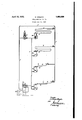
- FIG. 1 designates the steam pipe to which are connected two room heating plantsQ and 3 and two boiling tanks 4 and 5.
- the reduction of pressure in the heating plants andthe boiling tanks is unequal; In the former the reduction of pressure depends on the length and diameter of the heating tubes and on the temperature of the room, while in the latter it. depends on whether. the material to be boiled has to be brought to the boiling tem-z perature or whether the temperature already reached hasonlyto be kept up.
- the water of condensation is ledthrough the pipes 6 to the collecting pipe 7 and returned by the de vice 8 to the boiler 9.
- each pipe 6 Arranged'at-the end of each pipe 6 is a device 10 of well-known construction controlling the leading ofi of the water of condensation. 11 is a steam admis-c sionvalve whichis connected with the condensate collecting pipe 7 and the live steam pipe 1. The load on the valve-is variable. Its construction may be of a Well-known kind; it may. for instance be a spring-weighted check valve. 7 1
- the collecting pipe 7 for the water of condensation is preferably insulated to prevent radiation of heat.
- the regulation of the drop of pressure may also be effected in another manner, such as for example by means of a valve which is loaded by a diaphragm or piston and which allows water to flow from the condensate collecting pipe to the return device or the like only when the difierence of pressure between the live steam pipe and the condensate collecting pipe has fallen to a predetermined amount.
- the regulation may for instance be effected by the aid of a clockwork in such a manner that the pressure in the condensate collecting pipe'is raised only gradually, which means that the difierence of pressure between the live steam pipe and the condensate collecting pipe is only gradually reduced by the admission of steam or the like into the collecting pipe.
- a main open to a source of steam under pressure, a plurality of heating units connected to the steam main and usingsteam at differentpressures, a condensate pipe common to the heating units and closed against the atmosphere, a
- a main open to a source of steam under pressure, a plurality of heating units connected to the steam main and using steam at different pressures, a condensate pipe common to the heating units and closed against the atmosphere, a regulating device interposed between each heating unit and the condensate pipe, a bypass connecting the steam main and the condensate pipe, and an automatically controlled cut-ofi in the by-pass designed to admit steam from the steam main into the condensate pipe when and as long as the pressure in this pipe is below a predetermined maximum.
- a main open to a source of steam under pressure, a plurality of heating units connected with the steam main and using steam at different pressures, a condensate pipe common to the heating units and closed against the atmosphere, regulating means adjusted for a predetermined maximum drop of pressure and interposed between each heating unit and the condensate pipe, a by-pass connecting the steam main and the condensate pipe, and an automatically controlled cut-off in the bypass designed to admit steam into the con densate pipe when and as long as pressure in this pipe is below a predetermined upper limit within the said maximum drop of pressure.
Landscapes
- Engineering & Computer Science (AREA)
- Physics & Mathematics (AREA)
- Thermal Sciences (AREA)
- Chemical & Material Sciences (AREA)
- Combustion & Propulsion (AREA)
- Mechanical Engineering (AREA)
- General Engineering & Computer Science (AREA)
- Control Of Steam Boilers And Waste-Gas Boilers (AREA)
Description
April 12, 1932.
H. KRANTZ STEAM HEATING SYSTEM Fiied June 21, 1928 Patented Apr. 12, 1932 PATENT @FFEQE HUBERT KR- ANTZ OF AACHEN, GERMANY STEAM HEATING SYSTEM Application filed Julie 21, 1928, Serial No. 287,229, and in Germany June 27,1927.
. This invention relates to steam heating sys-, terns comprising a plurality of mean or high pressure heating plantswhich work at different pressures and the water of condensa- '5 tion of which is led into one common condensate collecting pipe, which is shut oii with relation to the atmosphere and from which the water is either returned to the boiler or otherwise utilized. In the known heating systems of this kind difiiculties arise owing to the difference of pressure in the several heating plants and the condensate collecting pipe. The difierence of pressure between the several heating plants is either due to the variations of pressure'of the steam used or to the varying reduction of pressure in the several plants. It has been proposed in heating systems to arrange at the eXit end of each heating coil a device for automatically reducing the different pressures to one uniform pressure which is somewhat higher than the pressure in the condensate collecting pipe. These known devices include a check valve which is loaded by a float the weight of which is more or less balanced by the buoyancy of the water accumulating in the device. When the. float is wholly immersed in water, no reduction or only the minimum reduction of pressure takes place. The reduction of pressure is greatest when the float does not immerse in the water at all. This known regulation of pressures therefore entirely depends on. the weight of the float. As the required range of pressure regulation cannot 5 be accurately ascertained in advance, especially in cases where many heating plants empty into one and the same collecting pipe for the water of condensation, the following drawbacks are entailed. The fioats are either chosen for too great a range of pressure, i. e. they are made too heavy, in which case the pressure is reduced more than required and water hammers are liable to occur, or the floats are chosen for too small a range of pressure, i. e. they are made too light, in which case a perfect draining of all plants can nolonger be attained.
Now, the invention has for its object to avoid the said drawbacks and to provide a 50. mean or high pressure steam heating system inwhich the drop of pressure between the live steam pipe and the condensate collecting pipe isautomatically held at a definite maximum limit by. a centrally arranged adjustable device, which may in itself be of a well-known character and, for example, may, be a variably loaded valve arranged in the collecting pipe and adapted to automatically admit steam into, the collecting pipe when the pressure in the same drops below a predetermined amount. a
The water ofcondensation may be led from the several heating plants into the collecting pipe by any well-known devices.
The accompanying drawing diagrammatically illustrates, by way of example, a heating system constructed in accordance with the invention. 1 designates the steam pipe to which are connected two room heating plantsQ and 3 and two boiling tanks 4 and 5. The reduction of pressure in the heating plants andthe boiling tanks is unequal; In the former the reduction of pressure depends on the length and diameter of the heating tubes and on the temperature of the room, while in the latter it. depends on whether. the material to be boiled has to be brought to the boiling tem-z perature or whether the temperature already reached hasonlyto be kept up. 1 The water of condensation is ledthrough the pipes 6 to the collecting pipe 7 and returned by the de vice 8 to the boiler 9. Arranged'at-the end of each pipe 6 is a device 10 of well-known construction controlling the leading ofi of the water of condensation. 11 is a steam admis-c sionvalve whichis connected with the condensate collecting pipe 7 and the live steam pipe 1. The load on the valve-is variable. Its construction may be of a Well-known kind; it may. for instance be a spring-weighted check valve. 7 1
The operation of the heating system is as follows. ,It is assumed that the pressure above atmospheric in the steam pipe 1 is 6 at- I mospheres and it is further assumed, that in I the case of the greatest output, 'the'pressure at the end of the heating plant 2 is 4.2 atmos pheres, that at the end of the heating plant 3 it is 3.9 atmospheres and that'at the boiling tanks 4 and 5 it is 3.7 atmospheres. Under these circumstances, the automatic steam admission valve 11 is adjusted in such a manner that it reduces the pressure of the steam flowing through it by a little more than (6-0, 7) =23 atmospheres above atmospheric. WVhen the difference of pressure between the steam pipe and the condensate collecting pipe becomes greater, live steam is automatically admitted by the valve 11 into the collecting pipe. When the difierenceof pressure becomes smaller the admission of steam through the valve 11 is automatically cut off. A perfect draining of the entire system is thus secured in a simple manner. At the same time losses of heat and disturbances of working and more particularly water-hammers in the piping are avoided. The collecting pipe 7 for the water of condensation is preferably insulated to prevent radiation of heat.
Instead of supplying steam to the collect ing pipe there may also be supplied air.
The regulation of the drop of pressure may also be effected in another manner, such as for example by means of a valve which is loaded by a diaphragm or piston and which allows water to flow from the condensate collecting pipe to the return device or the like only when the difierence of pressure between the live steam pipe and the condensate collecting pipe has fallen to a predetermined amount.
In case it is desired to have no back pressure whatever when the system is started, the regulation may for instance be effected by the aid of a clockwork in such a manner that the pressure in the condensate collecting pipe'is raised only gradually, which means that the difierence of pressure between the live steam pipe and the condensate collecting pipe is only gradually reduced by the admission of steam or the like into the collecting pipe.
Having thus described my invention, what I claim as new and desire to secure by Letters-Patent, is
1. In a steam heating system, a main open to a source of steam under pressure, a plurality of heating units connected to the steam main and usingsteam at differentpressures, a condensate pipe common to the heating units and closed against the atmosphere, a
pressure regulating device interposed between each heating unit and the condensate pipe, a by-pass connecting the steam main and the condensate pipe, and means in the by-pass to automatically control communication between the steam main and the condensate pipe in accordance with the difference in pressure between that of the steam source: and that in the condensate pipe.
2. In a steam heating system, a main open to a source of steam under pressure, a plurality of heating units connected to the steam main and using steam at different pressures, a condensate pipe common to the heating units and closed against the atmosphere, a regulating device interposed between each heating unit and the condensate pipe, a bypass connecting the steam main and the condensate pipe, and an automatically controlled cut-ofi in the by-pass designed to admit steam from the steam main into the condensate pipe when and as long as the pressure in this pipe is below a predetermined maximum.
3. In a steam heating system, a main open to a source of steam under pressure, a plurality of heating units connected with the steam main and using steam at different pressures, a condensate pipe common to the heating units and closed against the atmosphere, regulating means adjusted for a predetermined maximum drop of pressure and interposed between each heating unit and the condensate pipe, a by-pass connecting the steam main and the condensate pipe, and an automatically controlled cut-off in the bypass designed to admit steam into the con densate pipe when and as long as pressure in this pipe is below a predetermined upper limit within the said maximum drop of pressure.
In testimony whereof I have signed my name to this specification.
DR. HUBERTKRANTZ.
Applications Claiming Priority (1)
| Application Number | Priority Date | Filing Date | Title |
|---|---|---|---|
| DE1853820X | 1927-06-27 |
Publications (1)
| Publication Number | Publication Date |
|---|---|
| US1853820A true US1853820A (en) | 1932-04-12 |
Family
ID=7746124
Family Applications (1)
| Application Number | Title | Priority Date | Filing Date |
|---|---|---|---|
| US287229A Expired - Lifetime US1853820A (en) | 1927-06-27 | 1928-06-21 | Steam heating system |
Country Status (1)
| Country | Link |
|---|---|
| US (1) | US1853820A (en) |
-
1928
- 1928-06-21 US US287229A patent/US1853820A/en not_active Expired - Lifetime
Similar Documents
| Publication | Publication Date | Title |
|---|---|---|
| US2316237A (en) | Means for controlling the supply of air to the closed cabins of aircraft | |
| US2193141A (en) | Heating system for supercharged cabins | |
| US2515647A (en) | Clear channel steam system | |
| US1853820A (en) | Steam heating system | |
| US2870751A (en) | Pumpless liquid heater and translator | |
| US2643520A (en) | Feed-water control system for steam power plants | |
| US2003585A (en) | Method and apparatus for heating with steam | |
| US944183A (en) | Heating system. | |
| US2636485A (en) | Closed feed system for steam power plants | |
| US1726730A (en) | of stockholm | |
| US2216245A (en) | Temperature control system | |
| US2636721A (en) | Steam pressure control for directcontact heaters operating on variable pressure steam | |
| US2635815A (en) | Method and means for the control of emulsion heat | |
| US2168902A (en) | Surface condenser | |
| US2663683A (en) | Apparatus for evaporating liquids | |
| US1966791A (en) | Method of and apparatus for handling heating system returns | |
| US1024547A (en) | Boyers | |
| US1646945A (en) | Method of and apparatus for automatically regulating the water level in steam boilers | |
| US2270510A (en) | Ratioed air control for steam heating systems | |
| US1544338A (en) | High-pressure-steam system | |
| US1771077A (en) | Method of heating by steam | |
| US2325487A (en) | Steam heating system | |
| US1629043A (en) | Apparatus for central heating | |
| US2256566A (en) | Air conditioning apparatus | |
| US2363795A (en) | Hot-water heating system |