US1853819A - Refrigerant container - Google Patents
Refrigerant container Download PDFInfo
- Publication number
- US1853819A US1853819A US509527A US50952731A US1853819A US 1853819 A US1853819 A US 1853819A US 509527 A US509527 A US 509527A US 50952731 A US50952731 A US 50952731A US 1853819 A US1853819 A US 1853819A
- Authority
- US
- United States
- Prior art keywords
- cylinder
- head
- outer cylinder
- inner cylinder
- cylinders
- Prior art date
- Legal status (The legal status is an assumption and is not a legal conclusion. Google has not performed a legal analysis and makes no representation as to the accuracy of the status listed.)
- Expired - Lifetime
Links
Images

Classifications
-
- A—HUMAN NECESSITIES
- A23—FOODS OR FOODSTUFFS; TREATMENT THEREOF, NOT COVERED BY OTHER CLASSES
- A23G—COCOA; COCOA PRODUCTS, e.g. CHOCOLATE; SUBSTITUTES FOR COCOA OR COCOA PRODUCTS; CONFECTIONERY; CHEWING GUM; ICE-CREAM; PREPARATION THEREOF
- A23G9/00—Frozen sweets, e.g. ice confectionery, ice-cream; Mixtures therefor
- A23G9/04—Production of frozen sweets, e.g. ice-cream
- A23G9/22—Details, component parts or accessories of apparatus insofar as not peculiar to a single one of the preceding groups
Definitions
- ELTON D. KOBE, OF YORK, PENNSYLVANIA ihis invention relates to a refrigerant container designed primarily for use in connection with machines for manufacturing edibles of the frozen product type, such as cus- 5 tards, creams and ices, but it to be understood that a container in accordance with this invention may be employed in any connection for which it is found applicable, and the invention has for its object to provide, in a manner as hereinafter set forth a compositeinsulated-container in the form of a barrel for not only maintaining the freezing temperature of the refrigerant during the manufacture of the product to facilitate production, but further for supporting the production and discharge elements of the machine.
- a further object of the invention is to provide, in a manner as hereinafter set forth, a composite-insulated-container for the purpose referred to so constructed and arranged as to provide a permanently bright, nonsweating outer periphery whereby the container will at all times have a pleasing and sanitary appearance.
- a further object of the invention is toprovide, in a manner as hereinafter set forth, a composite-insulated-refrigerant container for thepurpose referred to and of barrel-like contour and having means to provide the outer periphery of its body'portion and its outer end or head from sweating whereby the container will have a pleasing and sanitary appearance.
- the invention consists of the novel construction, combination and arrangement of parts as hereinafter more specifically de scribed, and illustrated in the .accompanying drawings wherein is shown an embodiment of the invention, but it is to be understoodthat changes, variations and modifications REFRIGERANT CONTAINER Application filed January 17, 1931. Serial No. 509,527.
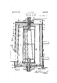
- Figure 1 is a longitudinal sectional view of a refrigerant container in accordance with this invention showingthe adaptation thereof with respect to certain of the elements of a frozen product machine.
- Figure 2 is a side elevation of a refrigerant container in accordance with this invenparts
- Figure 3 is a section on the line 3-3 Fig-
- the container includes a longitudinally disposed inner metallic cylinder 1 which slightly tapers from its rear to its front end, a longitudinally disposed outer metallic cylinder 2 of greater diameter and length than cylinder 1 and which slightly tapers from its rear to its front end, a sectional metallic front head member 3, a metallic rear head member 41, a permanently bright, metallic front cap 5 possessing a non-sweating characteristic, a metallic retaining disc or cap 6 for the rear end of the container, and a permanently bright metallic tapered sleeve 7 completely encompassing the outer metallic cylinder 2 and possessing a non-sweating characteristic.
- the thickness of the body of the sleeve 7 is less than the thickness of either one of the cylinders.
- the head members 3 and 4 in connection with the inner cylinder 1 provides a refrigerant chamber 8.
- the refrigerant will be in the form of brine.
- the head member 8 is formed of two sections, one of which is indicated at 9 and the other at 10.
- the section 9 is in the form of a flat annulus having projecting rearwardly from its rear face an annular flange 12 positioned between the edges of the annulus.
- the section 10 is in the form of a circular disc 13 having an axial opening 14 and a forwardly directedannular flange 15 registering with the wall of the opening 14.
- the disc 10 abuts against the front'face of the annulus, secured by holdfast devices 16 to the annulus and extends across the opening provided by the annulus.
- The' opening provided by the annulus is of materially greater diameter than the opening provided in the disc 13.
- the head member 3 is positioned within the outer cylinder 2 at a point rearwardly with respect to the front end of said cylinder 2.
- the head member 3 abuts against the front end of the inner cylinder 1 and the latter has its front end supported upon the flange 12.
- the head member 4 is in the form of a circular disc 17 provided with an axial opening 18 and has formed integral with the front face, as well as projecting forwardly therefrom an annular flange 19. Tie head member 4 abuts against the inner face of the outer cylinder 2 and also against the rear end of the inner cylinder 1. The rear end of the inner cylinder 1 is supported upon the flange 19. The flanges 12 and 19 snugly engage the inner face of the cylinder 1 at the ends of the latter.
- a metallic ring 20 of the desired thickness Positioned within the front end of the cylinder 2 and abutting against the forward face of the annulus 10, as well as snugly engaging the inner cylinder 2 is a metallic ring 20 of the desired thickness.
- the ring 20 has its front edge flush with the front edge of the outer cylinder 2.
- an insulating body 21 Interposed between the cylinders 1 and 2 and abutting the head members 3, 4 is an insulating body 21 preferably in the form of cork and each side of said body has a coating of a preservative, preferably creosote.
- the coating at the outer side of body 21 is indicated at 22 and at the inner side at 23.
- the coatings of creosote extend from the head member 3 to the head member 4.
- the front cap 5 includes a circular body portion 24 provided with an axial opening 25 and a forwardly directed angle shaped flange 26 which registers with the wall of the opening 25, that is to say the longitudinal leg of flange 26.
- the outer leg of flange 26 is extended inwardly from the longitudinal leg and opposes in spaced relation the flange 15.
- the body portion 24 is formed with forwardly directed angle shaped flange 27 having its longitudinal leg abutting the inner face of ring 20 and its other leg abutting against the front edge of ring 20 and the front edge of cylinder 2.
- the sleeve 7 has its front end seated upon the flange 27.
- an insulating body 28 of cork having an axial opening 29. The insulating body 28 abuts against the inner face of the ring 20 throughout.
- Spaced reinforcing bands 29 extend circumferentially of the sleeve 7 and which acts to couple the cylinders 1, 2, insulating body 21 and sleeve 7 together.
- the reinforcing bands are constructed of metal possessing a permanently bright and non-sweating characteristic.
- the outer cylinder 2 and sleeve 7 is extended at the bottom at its rear as at 30, 31 respectively.
- the extended portions 30, 31 act as a support for a refrigerant overflow collector 32, provided with an intake 33.
- the rear cap 6 is in the form of a circular disc and which ispositioned within the outer cylinder 2 forwardly with respect to the rear end of the latter and interposed between cap 6 and rear head member 4 is an insulating body 33 preferably in the form of cork.
- the rear cap 6 and insulating body 33 are apertured as at 34, 35 respectively for the passage of the journal 10.
- the container includes a refrigerant overflow pipe 36 which leads to the overflow collector 32.
- the overflow pipe 36 communicates with the refrigerant chamber and extends through the rear head member 4, in sulating body 33 and rear cap 6.
- the insulating body 33 and rear cap are provided with axial openings 37, 38 respectively which register with the opening 18 formed in the rear head member 4.
- the container includes a drain pipe 39 which leads from the refrigerant chamber 8 and extends through the inner cylinder 1, insulating body 21, outer cylinder 2 and sleeve 7.
- the production elements of the machine are arranged in the refrigerant chamber 8 and are generally indicated at 40.
- the operating and supply means for the production elements 40 are generally indicated at 41 and extend through the aligning openings 18, 37 and 38.
- the discharge elements of the machine are generally indicated at 42 and they extend through the flanges 15 and 26.
- a packing means 43 is connected with the flange 15 and encompasses the elements 42.
- the top of the container is provided with an intake opening 44 and communicating therewith is a hopper 45.
- the sleeve 7 is formed of a ferrous alloy known as Alleghany metal.
- the alloy is composed principally of iron, chromium, nickel in the order named and containing small amounts of manganese, silicon and carbon.
- the cylinders 1 and 2 as well as the head members are constructed of rust proof steel, the sleeve 7 and front and rear caps of a ferrous alloy.
- a composite-insulated-refrigerant container as set up in a manner as herein before referred to will retain the freezing temperature, eliminates sweating, saves ice and provides for the external surface thereof to appear in a sanitary and bright condition.
- a refrigerant container for frozen prod- I not machines and of barrel-like form compristhe latter, a rear head member abutting the rear end of the inner cylinder and the inner face of the outer cylinder forwardly of the rear end of the latter, an insulating body interposed between said cylinders and said head members, each of said head members having an axial opening, and a sleeve encompassing co-mpletely said outer cylinder and possessing a permanently bright characteristic.
- a refrigerant container for frozen product machines and of barrel-like form comprising an inner cylinder, an outer cylinder, a front head member abutting the forward end of the inner cylinder and inner face of the outer cylinder rearwardly of the front end of the latter, a rear head member abutting the rear end of the inner cylinder and the inner face of the outer cylinder forwardly of the rear end of the latter, an insulating body interposed between said cylinders and said head members, each of said head members having an axial opening, a sleeve encompassing completely said outer cylinder and possessing a permanently bright characteristic, a front cap connected with said outer cylinder and spaced from said front head men; her and having an axial opening, a rear cap connected with said outer cylinderand opposing in spaced relation said rear head member and having an axial opening,and insulating bodies interposed between said caps and head members and provided with axial openings.
- a refrigerant container for frozen product machines and of barrel-like form comprising an inner cylinder, an outer cylinder, a front head member abutting the forward end of the inner cylinder and inner face of the outer cylinder rearwardly of the front end of the latter, a rear head member abutting the rear end of the inner cylinder and the inner face of the outer cylinder forwardly of the rear end of the latter, an insulating body interposed between said cylinders and said head members, each of said head members having an axial opening, and a sleeve encompassing completely said outer cylinder and possessing a permanently bright characteristic, said insulating body having its inner and outer faces provided with acoating of creosote.
- a refrigerant container for frozen product machines and of barrel-like form comprising an inner cylinder, an outer sylinder of greater length than said inner cylinder and spaced from the latter, said cylinders being constructed of metallic material, a metallic front head member abutting the forward end I of the inner cylinder and inner face of the outer cylinder rearwardly of the front end of the latter, a rear head memberabutting the rear end of the inner cylinder and the inner face of the outer cylinder forwardly of the rear end of the latter, insulating means "be tween said head members and said cylinders,
- a sleeve encompassing said outer cylinder, front and rear cap members, insulating means between said cap members and said head members, theinsulating means between said cap and head members and the said cap and head members having axial openings aligning with each other.
- a refrigerant container for frozen product machines and of barrel-like form comprising an inner cylinder, an outer cylinder, said cylinders being formed of metallic material, said outer cylinder being of greater length than said inner clyinder and project-' ing from each end of the latter, a front head member abutting against the forward end of said inner cylinder and engaging the inner face of said outer cylinder rearwardly of its front end, a rear head member abutting the rear end of said inner cylinder and the inner face of said outer cylinder adjacent the rear 1 end of the latter, said head members having their opposed faces provided with flanges for supporting said inner cylinder, a ring abutting the front head member-and the inner face of said outer cylinder forwardly of said front head member, a front cap abutting said ring and the forward end of said outer cylin der and spaced from said front head member, a rear cap abutting the inner face of' said outer cylinder and spaced from said rear head member, insulating means interposed between
- a refrigerant container for frozen product machines land of barrel-like form comprisingan inner cylinder, an outer cylinder, said cylinders being formed of metallic mate-- rial, said outer cylinder being of greater length than said inner cylinder and projecting from each end of the latter,a front head member abutting against the forward end of said inner cylinder and engaging the inner face of saidouter cylinder rearwardly of its front end, a rear head member abutting the rear end of said inner cylinder and the inner face of said outer cylinder adjacent the rear end of the latter, said head members having their opposed faces provided with flanges for supporting said inner cylinder, a ringabuttingthe front head member and the inner face of said outer cylinder forwardly of said front head member, afront cap abutting said ring and the forwardend of said outer cylinder and spaced from said front head member, a rear cap abutting the inner face of said outer cylinder and spaced from said rear head member, insulating means interposed between said cylinders and head members and said
- a refrigerant container for frozen product machines and of barrel-like form comprising an inner cylinder, an outer cylinder, said cylinders being formed of metallic material, said outer cylinder being of; greater length than said inner cylinder and projecting from each end of the latter, a front head member abutting against the forward end of said inner cylinder and engaging the inner face of said outer cylinder rearwardly of its front end, a rear head member abutting the rear end of said inner cylinder and the inner face of said outer cylinder adjacent the rear end of the latter, said head members having their opposed faces provided with flanges for supporting said inner cylinder, a ring abutting the front head member and the inner face of said outer cylinder forwardly of said front head member, a front cap abutting said ring and the forward end of said outer cylinder and spaced from said front head member, a rear cap abutting the inner face of said outer cylinder and spaced from said rear head member, insulating means interposed between said cylinders and head members and said head members and
- a refrigerant container for frozen product machines and of barrel-like form comprising inner and outer metallic cylinders, said outer cylinder encompassing. in spaced relation said inner cylinder and of greater length than the length of the latter, head members abutting the ends of said inner cylinder and the inner face of said outer cylinder and provided with means for supporting said inner cylinder, insulating means interposed between said cylinders and head members, said cylinders, head members and insulating means providing a composite barrel, said barrel formed with a refrigerant supply opening, said inner cylinder in connection with said head members forming a refrigerant chamber, means arranged against the outer faces of said head members for insulating them, and caps positioned against the insulating means for said head members.
- a refrigerant container for frozen product machines and of barrel-like form comprising inner and outer metallic cylinders said outer cylinder encompassing in spaced relation said inner cylinder and of greater length than the length of the latter, head members abutting the ends of said inner cylinder and the inner face of said outer cylinder and provided with means for supporting said inner cylinder, insulating means interposed between said cylinders and head members, said cylinders, head members and insulating means providing a composite barrel, said barrel formed with a refrigerant supply opening, said inner cylinder in connection with said head members forming a refrigerant chamber, means arranged against the outer faces of said head members for insulatingthem, caps positioned against the insulating means for said head members, and a sleeve completely encompassing said outer cylinder and possessing a permanently bright characteristic.
- a refrigerant container for frozen product machines and of barrel-like form comprising inner and outer metallic cylinders, said outer cylinder encompassing in spaced relation said inner cylinder and of greater length than the length of the latter, head members abutting the ends of said inner cylinder and the inner face of said outer cylinder and provided with means for supporting said inner cylinder, insulating means interposed between said cylinders and head members, said cylinders, head members and insulating means providing a composite barrel, said barrel formed with a refrigerant supply opening, said inner cylinder in connection with said head members forming a refrigerant chamber, said insulating means conforming in contour to said cylinders and having its inner and outer faces provided with a preservative coating, means arranged against the outer faces of said head members for insulating them, and caps positioned against the insulating means for said head members.
- a refrigerant container for frozen product machines and of barrel-like form comprising inner and outer metallic cylinders, said outer cylinder encompassing in spaced relation said inner cylinder and of greater length than the length of the latter, head members abutting the ends of said inner cylinder and the inner face of said outer cylinder and provided with means for supporting said inner cylinder, insulating means interposed between said cylinders and head members, said cylinders, head members and insulating means providing a composite bar rel, said barrel formed with a refrigerant supply opening, said inner cylinder in connection with said head members forming a refrigerant chamber, said insulating means conforming in contour to said cylinders and having its inner and outer faces provided with a preservative coating, means arranged against the outer faces of said head members for insulating them, caps positioned against the insulating means for said head members, and a sleeve completely encompassing said outer cylinder and possessing a permanently bright characteristic.
- a refrigerant container for frozen product machines and of barrel-like form comprising inner and outer metallic cylinders, said outer cylinder encompassing in spaced relation said inner cylinder and of greater length than the length of the latter, head members abutting the ends of said inner cylinder and the inner face of said outer cylinder and provided with means for supporting said inner cylinder, insulating means interposed between said cylinders and head members, said cylinders, head members and insulating means providing a composite barrel, said barrel formed with a refrigerant supply opening, said inner cylinder in connection with said head members forming a refrigerant chamber, means arranged against the outer faces of said head members for insulating them, caps positioned against the insulating means for said head members, a sleeve completely encompassing said outer cylinder and possessing a permanently bright characteristic, said cap members and head members having aligning openings, and the insulating means for said head members having openings axially thereof.
Description
April 12, 1932. KOHR 1,853,819
REFRIGERANT CONTAINER- Filed Jan. 17, 1931 2 Sheets-Sheet 1 ENTOR. I g Ellbn Dffh r A TTORNEY.
April 12, 1932. E. D. KOHR REFRIGERANT CONTAINER Filed Jan '17, 1951 2 Sheets-Sheet 2 INVENTOR. Elia): 17.11571! W ATTORNI Z'Y.
Patented Apr. 12 1932 UNETED stares ears;
ELTON D. KOBE, OF YORK, PENNSYLVANIA ihis invention relates to a refrigerant container designed primarily for use in connection with machines for manufacturing edibles of the frozen product type, such as cus- 5 tards, creams and ices, but it to be understood that a container in accordance with this invention may be employed in any connection for which it is found applicable, and the invention has for its object to provide, in a manner as hereinafter set forth a compositeinsulated-container in the form of a barrel for not only maintaining the freezing temperature of the refrigerant during the manufacture of the product to facilitate production, but further for supporting the production and discharge elements of the machine.
A further object of the invention is to provide, in a manner as hereinafter set forth, a composite-insulated-container for the purpose referred to so constructed and arranged as to provide a permanently bright, nonsweating outer periphery whereby the container will at all times have a pleasing and sanitary appearance.
A further object of the invention is toprovide, in a manner as hereinafter set forth, a composite-insulated-refrigerant container for thepurpose referred to and of barrel-like contour and having means to provide the outer periphery of its body'portion and its outer end or head from sweating whereby the container will have a pleasing and sanitary appearance.
Further objects of the invention are to provide, in a manner as hereinafter set forth, a composite-insulated-refrigerant container for the purpose referred to which is simple in its construction and arrangement, strong, durable, compact, sanitary, thoroughly efficient in its use, readily assembled and comparatively inexpensive to set up.
With the foregoing and other objects in view, the invention consists of the novel construction, combination and arrangement of parts as hereinafter more specifically de scribed, and illustrated in the .accompanying drawings wherein is shown an embodiment of the invention, but it is to be understoodthat changes, variations and modifications REFRIGERANT CONTAINER Application filed January 17, 1931. Serial No. 509,527.
characters denote tion.
r oFiFicE can be resorted to which fall within the scope of the claims hereunto appended.
In the drawings wherein like reference corresponding throughout the several views Figure 1 is a longitudinal sectional view of a refrigerant container in accordance with this invention showingthe adaptation thereof with respect to certain of the elements of a frozen product machine.
Figure 2 is a side elevation of a refrigerant container in accordance with this invenparts Figure 3 is a section on the line 3-3 Fig- The container includes a longitudinally disposed inner metallic cylinder 1 which slightly tapers from its rear to its front end, a longitudinally disposed outer metallic cylinder 2 of greater diameter and length than cylinder 1 and which slightly tapers from its rear to its front end, a sectional metallic front head member 3, a metallic rear head member 41, a permanently bright, metallic front cap 5 possessing a non-sweating characteristic, a metallic retaining disc or cap 6 for the rear end of the container, and a permanently bright metallic tapered sleeve 7 completely encompassing the outer metallic cylinder 2 and possessing a non-sweating characteristic. The thickness of the body of the sleeve 7 is less than the thickness of either one of the cylinders. The head members 3 and 4 in connection with the inner cylinder 1 provides a refrigerant chamber 8. Preferably the refrigerant will be in the form of brine.
The head member 8 is formed of two sections, one of which is indicated at 9 and the other at 10. The section 9 is in the form of a flat annulus having projecting rearwardly from its rear face an annular flange 12 positioned between the edges of the annulus. The section 10 is in the form of a circular disc 13 having an axial opening 14 and a forwardly directedannular flange 15 registering with the wall of the opening 14. The disc 10 abuts against the front'face of the annulus, secured by holdfast devices 16 to the annulus and extends across the opening provided by the annulus. .The' opening provided by the annulus is of materially greater diameter than the opening provided in the disc 13. The head member 3 is positioned within the outer cylinder 2 at a point rearwardly with respect to the front end of said cylinder 2. The head member 3 abuts against the front end of the inner cylinder 1 and the latter has its front end supported upon the flange 12.
The head member 4 is in the form of a circular disc 17 provided with an axial opening 18 and has formed integral with the front face, as well as projecting forwardly therefrom an annular flange 19. Tie head member 4 abuts against the inner face of the outer cylinder 2 and also against the rear end of the inner cylinder 1. The rear end of the inner cylinder 1 is supported upon the flange 19. The flanges 12 and 19 snugly engage the inner face of the cylinder 1 at the ends of the latter.
Positioned within the front end of the cylinder 2 and abutting against the forward face of the annulus 10, as well as snugly engaging the inner cylinder 2 is a metallic ring 20 of the desired thickness. The ring 20 has its front edge flush with the front edge of the outer cylinder 2.
Interposed between the cylinders 1 and 2 and abutting the head members 3, 4 is an insulating body 21 preferably in the form of cork and each side of said body has a coating of a preservative, preferably creosote. The coating at the outer side of body 21 is indicated at 22 and at the inner side at 23. The coatings of creosote extend from the head member 3 to the head member 4.
The front cap 5 includes a circular body portion 24 provided with an axial opening 25 and a forwardly directed angle shaped flange 26 which registers with the wall of the opening 25, that is to say the longitudinal leg of flange 26. The outer leg of flange 26 is extended inwardly from the longitudinal leg and opposes in spaced relation the flange 15. The body portion 24 is formed with forwardly directed angle shaped flange 27 having its longitudinal leg abutting the inner face of ring 20 and its other leg abutting against the front edge of ring 20 and the front edge of cylinder 2. The sleeve 7 has its front end seated upon the flange 27. Interposed between the body portion 24 of the front cap 5 and the front head member 3 is an insulating body 28 of cork having an axial opening 29. The insulating body 28 abuts against the inner face of the ring 20 throughout.
Spaced reinforcing bands 29 extend circumferentially of the sleeve 7 and which acts to couple the cylinders 1, 2, insulating body 21 and sleeve 7 together. The reinforcing bands are constructed of metal possessing a permanently bright and non-sweating characteristic. The outer cylinder 2 and sleeve 7 is extended at the bottom at its rear as at 30, 31 respectively. The extended portions 30, 31 act as a support for a refrigerant overflow collector 32, provided with an intake 33. The rear cap 6 is in the form of a circular disc and which ispositioned within the outer cylinder 2 forwardly with respect to the rear end of the latter and interposed between cap 6 and rear head member 4 is an insulating body 33 preferably in the form of cork. The rear cap 6 and insulating body 33 are apertured as at 34, 35 respectively for the passage of the journal 10.
The container includes a refrigerant overflow pipe 36 which leads to the overflow collector 32. The overflow pipe 36 communicates with the refrigerant chamber and extends through the rear head member 4, in sulating body 33 and rear cap 6. The insulating body 33 and rear cap are provided with axial openings 37, 38 respectively which register with the opening 18 formed in the rear head member 4. The container includes a drain pipe 39 which leads from the refrigerant chamber 8 and extends through the inner cylinder 1, insulating body 21, outer cylinder 2 and sleeve 7.
As illustrated the production elements of the machine are arranged in the refrigerant chamber 8 and are generally indicated at 40. The operating and supply means for the production elements 40 are generally indicated at 41 and extend through the aligning openings 18, 37 and 38. The discharge elements of the machine are generally indicated at 42 and they extend through the flanges 15 and 26. A packing means 43 is connected with the flange 15 and encompasses the elements 42.
The top of the container is provided with an intake opening 44 and communicating therewith is a hopper 45.
The sleeve 7 is formed of a ferrous alloy known as Alleghany metal. The alloy is composed principally of iron, chromium, nickel in the order named and containing small amounts of manganese, silicon and carbon.
The cylinders 1 and 2, as well as the head members are constructed of rust proof steel, the sleeve 7 and front and rear caps of a ferrous alloy.
A composite-insulated-refrigerant container as set up in a manner as herein before referred to will retain the freezing temperature, eliminates sweating, saves ice and provides for the external surface thereof to appear in a sanitary and bright condition.
What I claim is 1. A refrigerant container for frozen prod- I not machines and of barrel-like form compristhe latter, a rear head member abutting the rear end of the inner cylinder and the inner face of the outer cylinder forwardly of the rear end of the latter, an insulating body interposed between said cylinders and said head members, each of said head members having an axial opening, and a sleeve encompassing co-mpletely said outer cylinder and possessing a permanently bright characteristic.
2. A refrigerant container for frozen product machines and of barrel-like form comprising an inner cylinder, an outer cylinder, a front head member abutting the forward end of the inner cylinder and inner face of the outer cylinder rearwardly of the front end of the latter, a rear head member abutting the rear end of the inner cylinder and the inner face of the outer cylinder forwardly of the rear end of the latter, an insulating body interposed between said cylinders and said head members, each of said head members having an axial opening, a sleeve encompassing completely said outer cylinder and possessing a permanently bright characteristic, a front cap connected with said outer cylinder and spaced from said front head men; her and having an axial opening, a rear cap connected with said outer cylinderand opposing in spaced relation said rear head member and having an axial opening,and insulating bodies interposed between said caps and head members and provided with axial openings.
3. A refrigerant container for frozen product machines and of barrel-like form comprising an inner cylinder, an outer cylinder, a front head member abutting the forward end of the inner cylinder and inner face of the outer cylinder rearwardly of the front end of the latter, a rear head member abutting the rear end of the inner cylinder and the inner face of the outer cylinder forwardly of the rear end of the latter, an insulating body interposed between said cylinders and said head members, each of said head members having an axial opening, and a sleeve encompassing completely said outer cylinder and possessing a permanently bright characteristic, said insulating body having its inner and outer faces provided with acoating of creosote.
4. A refrigerant container for frozen product machines and of barrel-like form comprising an inner cylinder, an outer sylinder of greater length than said inner cylinder and spaced from the latter, said cylinders being constructed of metallic material, a metallic front head member abutting the forward end I of the inner cylinder and inner face of the outer cylinder rearwardly of the front end of the latter, a rear head memberabutting the rear end of the inner cylinder and the inner face of the outer cylinder forwardly of the rear end of the latter, insulating means "be tween said head members and said cylinders,
a sleeve encompassing said outer cylinder, front and rear cap members, insulating means between said cap members and said head members, theinsulating means between said cap and head members and the said cap and head members having axial openings aligning with each other.
5. A refrigerant container for frozen product machines and of barrel-like form comprising an inner cylinder, an outer cylinder, said cylinders being formed of metallic material, said outer cylinder being of greater length than said inner clyinder and project-' ing from each end of the latter, a front head member abutting against the forward end of said inner cylinder and engaging the inner face of said outer cylinder rearwardly of its front end, a rear head member abutting the rear end of said inner cylinder and the inner face of said outer cylinder adjacent the rear 1 end of the latter, said head members having their opposed faces provided with flanges for supporting said inner cylinder, a ring abutting the front head member-and the inner face of said outer cylinder forwardly of said front head member, a front cap abutting said ring and the forward end of said outer cylin der and spaced from said front head member, a rear cap abutting the inner face of' said outer cylinder and spaced from said rear head member, insulating means interposed between said cylinders and head members andsaid headme'mbers and caps, and said head 'andcap members and the insulating means between them being formed with axial aligning openings.
6. A refrigerant container for frozen product machines land of barrel-like form comprisingan inner cylinder, an outer cylinder, said cylinders being formed of metallic mate-- rial, said outer cylinder being of greater length than said inner cylinder and projecting from each end of the latter,a front head member abutting against the forward end of said inner cylinder and engaging the inner face of saidouter cylinder rearwardly of its front end, a rear head member abutting the rear end of said inner cylinder and the inner face of said outer cylinder adjacent the rear end of the latter, said head members having their opposed faces provided with flanges for supporting said inner cylinder, a ringabuttingthe front head member and the inner face of said outer cylinder forwardly of said front head member, afront cap abutting said ring and the forwardend of said outer cylinder and spaced from said front head member, a rear cap abutting the inner face of said outer cylinder and spaced from said rear head member, insulating means interposed between said cylinders and head members and said head members and caps, said head and cap members and the insulating means between characteristic and encompassing completely said outer cylinder and seating on the outer edge of said front cap.
7 A refrigerant container for frozen product machines and of barrel-like form comprising an inner cylinder, an outer cylinder, said cylinders being formed of metallic material, said outer cylinder being of; greater length than said inner cylinder and projecting from each end of the latter, a front head member abutting against the forward end of said inner cylinder and engaging the inner face of said outer cylinder rearwardly of its front end, a rear head member abutting the rear end of said inner cylinder and the inner face of said outer cylinder adjacent the rear end of the latter, said head members having their opposed faces provided with flanges for supporting said inner cylinder, a ring abutting the front head member and the inner face of said outer cylinder forwardly of said front head member, a front cap abutting said ring and the forward end of said outer cylinder and spaced from said front head member, a rear cap abutting the inner face of said outer cylinder and spaced from said rear head member, insulating means interposed between said cylinders and head members and said head members and caps, said head and cap members and the insulating means between them being formed with aXial aligning openings, a metallic sleeve possessing a bright characteristic and encompassing completely said outer cylinder and seating on the outer edge of said front cap, said inner cylinder and head members providing a refrigerant chamber, a drain pipe leading from said cylinder and extending through said sleeve, and an overflow pipe leading from said cylinder and extending through said rear head member and rear cap.
8. A refrigerant container for frozen product machines and of barrel-like form comprising inner and outer metallic cylinders, said outer cylinder encompassing. in spaced relation said inner cylinder and of greater length than the length of the latter, head members abutting the ends of said inner cylinder and the inner face of said outer cylinder and provided with means for supporting said inner cylinder, insulating means interposed between said cylinders and head members, said cylinders, head members and insulating means providing a composite barrel, said barrel formed with a refrigerant supply opening, said inner cylinder in connection with said head members forming a refrigerant chamber, means arranged against the outer faces of said head members for insulating them, and caps positioned against the insulating means for said head members.
9. A refrigerant container for frozen product machines and of barrel-like form comprising inner and outer metallic cylinders said outer cylinder encompassing in spaced relation said inner cylinder and of greater length than the length of the latter, head members abutting the ends of said inner cylinder and the inner face of said outer cylinder and provided with means for supporting said inner cylinder, insulating means interposed between said cylinders and head members, said cylinders, head members and insulating means providing a composite barrel, said barrel formed with a refrigerant supply opening, said inner cylinder in connection with said head members forming a refrigerant chamber, means arranged against the outer faces of said head members for insulatingthem, caps positioned against the insulating means for said head members, and a sleeve completely encompassing said outer cylinder and possessing a permanently bright characteristic.
10. A refrigerant container for frozen product machines and of barrel-like form comprising inner and outer metallic cylinders, said outer cylinder encompassing in spaced relation said inner cylinder and of greater length than the length of the latter, head members abutting the ends of said inner cylinder and the inner face of said outer cylinder and provided with means for supporting said inner cylinder, insulating means interposed between said cylinders and head members, said cylinders, head members and insulating means providing a composite barrel, said barrel formed with a refrigerant supply opening, said inner cylinder in connection with said head members forming a refrigerant chamber, said insulating means conforming in contour to said cylinders and having its inner and outer faces provided with a preservative coating, means arranged against the outer faces of said head members for insulating them, and caps positioned against the insulating means for said head members.
11. A refrigerant container for frozen product machines and of barrel-like form comprising inner and outer metallic cylinders, said outer cylinder encompassing in spaced relation said inner cylinder and of greater length than the length of the latter, head members abutting the ends of said inner cylinder and the inner face of said outer cylinder and provided with means for supporting said inner cylinder, insulating means interposed between said cylinders and head members, said cylinders, head members and insulating means providing a composite bar rel, said barrel formed with a refrigerant supply opening, said inner cylinder in connection with said head members forming a refrigerant chamber, said insulating means conforming in contour to said cylinders and having its inner and outer faces provided with a preservative coating, means arranged against the outer faces of said head members for insulating them, caps positioned against the insulating means for said head members, and a sleeve completely encompassing said outer cylinder and possessing a permanently bright characteristic. I
12. A refrigerant container for frozen product machines and of barrel-like form comprising inner and outer metallic cylinders, said outer cylinder encompassing in spaced relation said inner cylinder and of greater length than the length of the latter, head members abutting the ends of said inner cylinder and the inner face of said outer cylinder and provided with means for supporting said inner cylinder, insulating means interposed between said cylinders and head members, said cylinders, head members and insulating means providing a composite barrel, said barrel formed with a refrigerant supply opening, said inner cylinder in connection with said head members forming a refrigerant chamber, means arranged against the outer faces of said head members for insulating them, caps positioned against the insulating means for said head members, a sleeve completely encompassing said outer cylinder and possessing a permanently bright characteristic, said cap members and head members having aligning openings, and the insulating means for said head members having openings axially thereof.
In testimony whereof I affix my signature hereto.
ELTON D. KOHR.
Priority Applications (1)
| Application Number | Priority Date | Filing Date | Title |
|---|---|---|---|
| US509527A US1853819A (en) | 1931-01-17 | 1931-01-17 | Refrigerant container |
Applications Claiming Priority (1)
| Application Number | Priority Date | Filing Date | Title |
|---|---|---|---|
| US509527A US1853819A (en) | 1931-01-17 | 1931-01-17 | Refrigerant container |
Publications (1)
| Publication Number | Publication Date |
|---|---|
| US1853819A true US1853819A (en) | 1932-04-12 |
Family
ID=24026995
Family Applications (1)
| Application Number | Title | Priority Date | Filing Date |
|---|---|---|---|
| US509527A Expired - Lifetime US1853819A (en) | 1931-01-17 | 1931-01-17 | Refrigerant container |
Country Status (1)
| Country | Link |
|---|---|
| US (1) | US1853819A (en) |
-
1931
- 1931-01-17 US US509527A patent/US1853819A/en not_active Expired - Lifetime
Similar Documents
| Publication | Publication Date | Title |
|---|---|---|
| GB1465280A (en) | Ice cream freezer | |
| US1853819A (en) | Refrigerant container | |
| US2598962A (en) | Metal container having reinforced end seam | |
| GB474238A (en) | Improvements in or relating to joint-washers or gaskets | |
| US1908120A (en) | Process of making windshields for projectiles | |
| DE3149775A1 (en) | Mixture compressing internal combustion engine | |
| US2216667A (en) | Bung bush | |
| US1894043A (en) | Piston cylinder | |
| USD96582S (en) | Design fob an ice cream cone | |
| USD130689S (en) | Design foe a milk bottle | |
| USD93286S (en) | Design fob a bottle | |
| USD129701S (en) | Design for a bolt back | |
| US1411244A (en) | Piston ring | |
| US2659638A (en) | Piston ring | |
| USD116188S (en) | Design fob a scaffold unit | |
| US2051546A (en) | Piston | |
| DE383604C (en) | Cylinder cover with liquid cooling for internal combustion engines with an inner and an outer base, which are connected to connecting pieces for receiving valves | |
| US1310983A (en) | Piston-rod packing. | |
| USD55868S (en) | Design for an ice-cream cone or similar article | |
| USD126856S (en) | Design foe a well bomb | |
| USD77145S (en) | Design fob ast ice-cream cone | |
| USD94815S (en) | Design fob a bicycle | |
| USD96329S (en) | Design for a wheel disk or similar | |
| USD84317S (en) | Design fob a bottle | |
| USD103339S (en) | Design fob a combined rotary pump |