US1853795A - Transmission and control mechanism for machine tools - Google Patents
Transmission and control mechanism for machine tools Download PDFInfo
- Publication number
- US1853795A US1853795A US136933A US13693326A US1853795A US 1853795 A US1853795 A US 1853795A US 136933 A US136933 A US 136933A US 13693326 A US13693326 A US 13693326A US 1853795 A US1853795 A US 1853795A
- Authority
- US
- United States
- Prior art keywords
- movement
- trip
- dog
- clutch
- support
- Prior art date
- Legal status (The legal status is an assumption and is not a legal conclusion. Google has not performed a legal analysis and makes no representation as to the accuracy of the status listed.)
- Expired - Lifetime
Links
- 230000005540 biological transmission Effects 0.000 title description 8
- 230000033001 locomotion Effects 0.000 description 48
- 241000282472 Canis lupus familiaris Species 0.000 description 30
- 238000010276 construction Methods 0.000 description 3
- 230000000694 effects Effects 0.000 description 2
- 230000000295 complement effect Effects 0.000 description 1
- 238000003801 milling Methods 0.000 description 1
- 230000004048 modification Effects 0.000 description 1
- 238000012986 modification Methods 0.000 description 1
- 230000000284 resting effect Effects 0.000 description 1
Images
Classifications
-
- B—PERFORMING OPERATIONS; TRANSPORTING
- B23—MACHINE TOOLS; METAL-WORKING NOT OTHERWISE PROVIDED FOR
- B23Q—DETAILS, COMPONENTS, OR ACCESSORIES FOR MACHINE TOOLS, e.g. ARRANGEMENTS FOR COPYING OR CONTROLLING; MACHINE TOOLS IN GENERAL CHARACTERISED BY THE CONSTRUCTION OF PARTICULAR DETAILS OR COMPONENTS; COMBINATIONS OR ASSOCIATIONS OF METAL-WORKING MACHINES, NOT DIRECTED TO A PARTICULAR RESULT
- B23Q5/00—Driving or feeding mechanisms; Control arrangements therefor
- B23Q5/22—Feeding members carrying tools or work
-
- B—PERFORMING OPERATIONS; TRANSPORTING
- B23—MACHINE TOOLS; METAL-WORKING NOT OTHERWISE PROVIDED FOR
- B23Q—DETAILS, COMPONENTS, OR ACCESSORIES FOR MACHINE TOOLS, e.g. ARRANGEMENTS FOR COPYING OR CONTROLLING; MACHINE TOOLS IN GENERAL CHARACTERISED BY THE CONSTRUCTION OF PARTICULAR DETAILS OR COMPONENTS; COMBINATIONS OR ASSOCIATIONS OF METAL-WORKING MACHINES, NOT DIRECTED TO A PARTICULAR RESULT
- B23Q2705/00—Driving working spindles or feeding members carrying tools or work
- B23Q2705/10—Feeding members carrying tools or work
- B23Q2705/104—Feeding members carrying tools or work for milling machines
-
- Y—GENERAL TAGGING OF NEW TECHNOLOGICAL DEVELOPMENTS; GENERAL TAGGING OF CROSS-SECTIONAL TECHNOLOGIES SPANNING OVER SEVERAL SECTIONS OF THE IPC; TECHNICAL SUBJECTS COVERED BY FORMER USPC CROSS-REFERENCE ART COLLECTIONS [XRACs] AND DIGESTS
- Y10—TECHNICAL SUBJECTS COVERED BY FORMER USPC
- Y10T—TECHNICAL SUBJECTS COVERED BY FORMER US CLASSIFICATION
- Y10T409/00—Gear cutting, milling, or planing
- Y10T409/30—Milling
- Y10T409/304536—Milling including means to infeed work to cutter
- Y10T409/304648—Milling including means to infeed work to cutter with control means energized in response to activator stimulated by condition sensor
- Y10T409/30476—In response to work or work carriage
- Y10T409/304872—In response to work or work carriage to control limit of infeed
-
- Y—GENERAL TAGGING OF NEW TECHNOLOGICAL DEVELOPMENTS; GENERAL TAGGING OF CROSS-SECTIONAL TECHNOLOGIES SPANNING OVER SEVERAL SECTIONS OF THE IPC; TECHNICAL SUBJECTS COVERED BY FORMER USPC CROSS-REFERENCE ART COLLECTIONS [XRACs] AND DIGESTS
- Y10—TECHNICAL SUBJECTS COVERED BY FORMER USPC
- Y10T—TECHNICAL SUBJECTS COVERED BY FORMER US CLASSIFICATION
- Y10T74/00—Machine element or mechanism
- Y10T74/18—Mechanical movements
- Y10T74/18056—Rotary to or from reciprocating or oscillating
- Y10T74/18072—Reciprocating carriage motions
Definitions
- This invention relates more particularly to transmission and control mechanism for machine tools having a Support movable by power.
- the drive train for such a movable support is ordinarily clutch controlled by the means of clutch members shiftable'into and out of driving engagement.
- Trip devices are ordinarily provided for shifting the clutch members, either by hand or at a predetermined point in the movement of the support, in the latter case usually by the means of dogs mounted upon the support, or'their equivalent.
- v the support train has been interrupted by such dogs, it may not be immediately re-engaged to cause support movement in the same direction because the parts which have contacted in the course of support movement, to shift the clutch member are still in contact and prevent the clutch member from being shifted back.
- Such operation of the parts is desirable for various reasons under most conditions of machine operation, but under certain conditions it is highly desirable that i the clutch should be immediately re-engageable.
- a main purpose of this invention is to provide a trip mechanism permitting immediate gore-engagement of a clutch member previously shifted out of the same engagement by the trip mechanism.
- Another purpose is to provide atrip mechanism which ordinarily operates in the usual manner to prevent clutch re-engagement as described above, but may, at the will of the operator be temporarily adjustedito'permit immediate clutch re-engagement.
- Another object is to provide a trip which is temporarily operable as described to per- ,mit immediate clutch re-engagement, only so long as the operator consciously determines such a. condition of operation but Which im .ed on a support or saddle 2 1n the usual manmediately resumes a condition preventing clutch re-engagement when the conscious attention of the operator is withdrawn.
- Another object is to simplify and improve the construction and operation of transmission and control mechanism'for amovable machine tool'support and particularly for one of the movable supports of a milling machine.
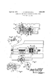
- Fig. 2 is a partial 'plan view of 'the table support, the table being removed to more clearly show portions'oi the drive train and Fig. Sis a partial end view showingsome of the mechanism of Fig. 1 in a different relative position of adjustment. '7
- Fig. 4 is apartialplanview showing some of the'mechanism of Fig. 2 ins. different po-,
- Fig. 5 is a frontview of a dog shown in Figs. 1, 3 and 4.
- a table screw 7 is rotatably supported from table 1 but is prevented from axial movement relative to the table in a manner which, being well known, is not shown in the drawings. Screw 7 is positioned to pass freelythrough suitable aligned bores inthe gear stems: 5a andfia, and is in threaded engagement with a nut 8 fixed 111 saddle 2.
- a sleeve 9 fitted between opposed-facesof the gears 5 and 6, and slidably keyed on sleeve 9 is a clutch member 10, provided on its opposite ends with clutch teeth 10a and 10?), respectively adapted for engagement with complementary clutch teeth on. the faces of gears 5 or 6 when the clutch member is shifted in the one or the other direction.
- the table 1 may be caused to move in the one or the other direction by the means of power derived from gear 1, accordingly as clutch member 10 is shifted in the one or the other direction.
- the clutch member 10 has a centralposition in which it is not engaged to be driven from either bevel gear and when in such position the table movement will stop.
- a trip post 11 is pivoted adjacent an edge of table 1 and is provided with an arm 11a carrying a pin portion 11f projecting downward into a slot 12a in an arm of a lever 12 which is pivoted on a pin 13 fixed in the saddle.
- Another arm of lever 12 has a portion 12b engaging a groove in a spool 14 fixed on a rod 15 slidably supported in saddle 2.
- Rod 15 carries a fork 16 engaging an annular groove 100 in the clutch member 10.
- the trip post 11 has fixed upon its upper end a member 110, loosely fitted between the parallel sides" of a slotted space between arms 17a and 17 5 of a trip part 17 which is pivoted about a pin 18 carried by the member. 110.
- trip part 17 may be turned, together with trip post 11 about the axis oftrip post 11, and by the mechanism described the clutch member 10 will be shifted accordingly.
- the arm portions 17a and 175. are respec tively provided with contact portions 19 and 20, so disposed that when clutch member 10 is in its central position of non-engagement the portions 19 and 20 are equally distant from the edge ofthe table.
- the contact portion 19 moves toward the table and the portion 20 away from the table, as shown in the full line position in Fig. 4;.
- the contact portion 20 moves toward the table as shown by the dotted line position of Fig. 41.
- a dog 21 is adj ustably fixed on the edge of the table by the means of a T slot and T bolt in the usual manner, and when suitably positioned, during the course of table movement to the right in Fig. 41, a beveled portion 21a will contact with the portion 19 and force the contacted portion back to the position shown in Fig. 2, thereby moving clutch member 10 to a central position as shown in Fig. 2, and interrupting the table movement.
- trip part 17 is cut away at 17d, Fig. 1, to permit movement as described about pivot 18. moves past the trip post 11, the table movement being continued as far as is desired, except as will be later noted, and the dog is then to the right of the trip post.
- the trip part 17 is shifted to the dotted position shown in Fig. t.
- the portion 20 then stands in the path of movement of the dog as it moves backward.
- the lower face of the dog is beveled as particularly shown in Fig.
- the bevel being such as to strike the top of the portion 20 during left hand table movement, and to force the portion 20 downward, pivoting about the pin 18 without movement of the postll, thus permitting the A dog. to retreat past the post without disengaging the clutch 10.
- a dog not shown, similar to dog 21 but of oppositely positioned bevels contacts the portion 29 to.
- the trip part portions 19 and 20 each have movement about the axis of post 11 in an upper and a lowerpath according to the position of the trip part about the axis of pin 18, and may be positioned for movement in either path, either by the hand grip 17 a or during the one direction of support movement by the beveled portion 21b of the dog 21.
- the movement in either path will effect the movement of clutch member 10, but the dog 21 is effective on the clutch member only when the trip parts are positioned in the one path although dog 22 is effective for either path. 7
- table movement may be established in either direction by manual movement of trip part 17, and during such movement a suitably positioned adjustable dog may automatically stop the table at any desired point, for instance, just before the-work is contacted by the cutter, following which the table movement may be immediately manually re-engaged to continue in the same direction as far as desired, for instance while the cutter passes over'the work piece.
- the table movement may then be reversed by the;
- a movable support, transmission mechanism therefor including a clutch member shiftable to engaged and to disengaged positions, a clutch member shiftable to engaged and to disengaged positions, a clutch member shiftable to engaged and to disengaged positions, a clutch member shiftable to engaged and to disengaged positions, a clutch member shiftable to engaged and to disengaged positions, a clutch member shiftable to engaged and to disengaged positions, a clutch member shiftable to engaged and to disengaged positions, a clutch member shiftable to engaged and to disengaged positions, a clutch member shiftable to engaged and to disengaged positions, a clutch member shiftable to engaged and to disengaged positions, a clutch member shiftable to engaged and to disengaged positions, a clutch member shiftable to engaged and to disengaged positions, a clutch member shiftable to engaged and to disengaged positions, a clutch member shiftable to engaged and to disengaged positions, a clutch member shiftable to engaged and to disengaged positions, a clutch member shiftable to engaged and to disengaged positions, a
Landscapes
- Engineering & Computer Science (AREA)
- Mechanical Engineering (AREA)
- Mechanical Operated Clutches (AREA)
Description
April 12, 1932. J. B. ARMITAGE ET AL 1,853,795
TRANSMISSION AND CONTROL MECHANISM FOR MACHINE TOOLS Filed Sept. 22, 1926 Patented Apr. 12, 1932 PATNT, OFFl-CE JOSEPHIBJ ARMITAGE; or ILWAUKRE,'AND RALPH E. sAvrNegor WA WATOSA, wIscoNSIN, AssIeNoRs To KEARNEY & T EoKRR CORPORATION, OF wRsT- LLIS;
WISCONSIN A TRANSMISSION .AINDCONTROL MECHANISM FOR MACHINE TOOLS Application and September 22,1926. semi 1\To. 136,933 .l 3
This invention relates more particularly to transmission and control mechanism for machine tools having a Support movable by power.
I t 'The drive train for such a movable support is ordinarily clutch controlled by the means of clutch members shiftable'into and out of driving engagement. Trip devices are ordinarily provided for shifting the clutch members, either by hand or at a predetermined point in the movement of the support, in the latter case usually by the means of dogs mounted upon the support, or'their equivalent. As heretofore constructed, when v the support train has been interrupted by such dogs, it may not be immediately re-engaged to cause support movement in the same direction because the parts which have contacted in the course of support movement, to shift the clutch member are still in contact and prevent the clutch member from being shifted back. Such operation of the parts is desirable for various reasons under most conditions of machine operation, but under certain conditions it is highly desirable that i the clutch should be immediately re-engageable.
A main purpose of this invention is to provide a trip mechanism permitting immediate gore-engagement of a clutch member previously shifted out of the same engagement by the trip mechanism.
Another purpose is to provide atrip mechanism which ordinarily operates in the usual manner to prevent clutch re-engagement as described above, but may, at the will of the operator be temporarily adjustedito'permit immediate clutch re-engagement.
- Another object is to provide a trip which is temporarily operable as described to per- ,mit immediate clutch re-engagement, only so long as the operator consciously determines such a. condition of operation but Which im .ed on a support or saddle 2 1n the usual manmediately resumes a condition preventing clutch re-engagement when the conscious attention of the operator is withdrawn.-
,Another object is to providein combination withthe trip means adjustable as described, other trip means invariably operable 5O tointerruptthe support drive train at a cer The invention trip mechanism.
tain predetermined point of support movement and which invariably prevents clutch re-engagement which would permit the support to travel further inthe same direction.
Another Object'is to provide means for interrupting the motion of a machine tool support at an intermediate point of its travel,
damage to the machine, work orcutter.
Another object is to simplify and improve the construction and operation of transmission and control mechanism'for amovable machine tool'support and particularly for one of the movable supports of a milling machine.
consists in the construction, arrangement and combination of parts as hereinafter particularly described and pointed out in the claims and insuch modifications along line l-"l of Fig. 2, of a movable machine tool table and a saddle or support therefor. I
-, Fig. 2 is a partial 'plan view of 'the table support, the table being removed to more clearly show portions'oi the drive train and Fig. Sis a partial end view showingsome of the mechanism of Fig. 1 in a different relative position of adjustment. '7
' Fig. 4: is apartialplanview showing some of the'mechanism of Fig. 2 ins. different po-,
sition of adjustment. 7
Fig. 5 is a frontview of a dog shown in Figs. 1, 3 and 4.
A table or worksupport 1 slidablyguid- I ner. Journaled in the support 2 is a bevel mission train terminating in a bevel: gear 4 fixed on the stem-of gear 3., "Bevel. gear 3 a 7 engages with the bevel gearsb and 6'to drive them in opposite directions the gears 5 and 6 being journaled in the saddle by means of stems 5a and 6a. A table screw 7 is rotatably supported from table 1 but is prevented from axial movement relative to the table in a manner which, being well known, is not shown in the drawings. Screw 7 is positioned to pass freelythrough suitable aligned bores inthe gear stems: 5a andfia, and is in threaded engagement with a nut 8 fixed 111 saddle 2. Slidably keyed on feed screw 7 is a sleeve 9 fitted between opposed-facesof the gears 5 and 6, and slidably keyed on sleeve 9 is a clutch member 10, provided on its opposite ends with clutch teeth 10a and 10?), respectively adapted for engagement with complementary clutch teeth on. the faces of gears 5 or 6 when the clutch member is shifted in the one or the other direction.
By the construction described the table 1 may be caused to move in the one or the other direction by the means of power derived from gear 1, accordingly as clutch member 10 is shifted in the one or the other direction. The clutch member 10 has a centralposition in which it is not engaged to be driven from either bevel gear and when in such position the table movement will stop.
For shifting clutch member 10, the following mechanism is provided. A trip post 11 is pivoted adjacent an edge of table 1 and is provided with an arm 11a carrying a pin portion 11f projecting downward into a slot 12a in an arm of a lever 12 which is pivoted on a pin 13 fixed in the saddle. Another arm of lever 12 has a portion 12b engaging a groove in a spool 14 fixed on a rod 15 slidably supported in saddle 2. Rod 15 carries a fork 16 engaging an annular groove 100 in the clutch member 10. The trip post 11 has fixed upon its upper end a member 110, loosely fitted between the parallel sides" of a slotted space between arms 17a and 17 5 of a trip part 17 which is pivoted about a pin 18 carried by the member. 110. Thus trip part 17 may be turned, together with trip post 11 about the axis oftrip post 11, and by the mechanism described the clutch member 10 will be shifted accordingly.
The arm portions 17a and 175. are respec tively provided with contact portions 19 and 20, so disposed that when clutch member 10 is in its central position of non-engagement the portions 19 and 20 are equally distant from the edge ofthe table. When the clutch member is moved to engage in a direction to move the table to the right in Fig. 4, the contact portion 19 moves toward the table and the portion 20 away from the table, as shown in the full line position in Fig. 4;. When the clutch member is moved to move the table to the left, the contact portion 20 moves toward the table as shown by the dotted line position of Fig. 41. A dog 21 is adj ustably fixed on the edge of the table by the means of a T slot and T bolt in the usual manner, and when suitably positioned, during the course of table movement to the right in Fig. 41, a beveled portion 21a will contact with the portion 19 and force the contacted portion back to the position shown in Fig. 2, thereby moving clutch member 10 to a central position as shown in Fig. 2, and interrupting the table movement.
The above described dog action takes'place if the trip part 17 is in the position about pivot pin 18 as shown in Fig. 1 to which the unbalanced weightof the overhanging hand grip portion 170 will normally move it, an under side of the part 17 then resting against the face of a suitable saddle portion 2a. As long as it remains in such position relative to Pivot pin 18, af being mmed by dog to a position of non-engagement of clutch 10, the contact between the angular dog face and the portion 19. prevents the trip part from being returned to the same position of clutch engagement, although it may be shifted to the opposite position to cause the table to move in the opposite direction, but if the trip part 18 to the position shown in Fig. 3, then the contact portion of the trip part is lowered beneath the dog, and the trip part may be is moved by the operator about the pivot pin immediately moved to again engage the clutch member 10 to continue the movement of the table in the same direction as previously moving. A portion of trip part 17 is cut away at 17d, Fig. 1, to permit movement as described about pivot 18. moves past the trip post 11, the table movement being continued as far as is desired, except as will be later noted, and the dog is then to the right of the trip post. When it is desired to move the table back again,to the left the trip part 17 is shifted to the dotted position shown in Fig. t. The portion 20 then stands in the path of movement of the dog as it moves backward. The lower face of the dog is beveled as particularly shown in Fig. 5, the bevel being such as to strike the top of the portion 20 during left hand table movement, and to force the portion 20 downward, pivoting about the pin 18 without movement of the postll, thus permitting the A dog. to retreat past the post without disengaging the clutch 10. For the left hand table movement a dog not shown, similar to dog 21 but of oppositely positioned bevels contacts the portion 29 to.
disengage the table drive during such movement ,'but forces the portion 19 downward to pass over it without movement of trip post 11 during right hand movement.
The dog then ioo As previously noted 1t 1s sometimes very desirable to re-engage table movement in the same direction when it has been disengaged one of the adjustable dogs. But to. prevent the table movement being continued to a point where damage may result, 'other'dogs are provided which are not adjustable, and
which cannot be avoided by movement of trip space occupiedby the adjustable dogs but,
so positioned that a beveled portion 22a will contact with the lever portion 19 just before the table reaches the limit of its right hand travel, after which the trip part will be forced by the dog to the position in which clutch member 10 is disengaged. Adog not shown, similar to the dog 22 is fixed with the table to contact with the portion 20 and dis engage clutch member 10 just before the table reaches the limit of its left hand movement.
It will be seen that the trip part portions 19 and 20 each have movement about the axis of post 11 in an upper and a lowerpath according to the position of the trip part about the axis of pin 18, and may be positioned for movement in either path, either by the hand grip 17 a or during the one direction of support movement by the beveled portion 21b of the dog 21. The movement in either path will effect the movement of clutch member 10, but the dog 21 is effective on the clutch member only when the trip parts are positioned in the one path although dog 22 is effective for either path. 7
From the foregoing description it will be seen that table movement may be established in either direction by manual movement of trip part 17, and during such movement a suitably positioned adjustable dog may automatically stop the table at any desired point, for instance, just before the-work is contacted by the cutter, following which the table movement may be immediately manually re-engaged to continue in the same direction as far as desired, for instance while the cutter passes over'the work piece. The table movement may then be reversed by the;
means of trip part 17 and the table traversed back to the starting point during which return movement the dog will pass the trip part 17 and trip post 11 without affecting the position of clutch 10. Such a cycle of machine movement isparticularly desirable rupted by the dog just before the work and cutter contact, may be established'again after the table drive train has been adjusted to a rate suitable for cutting.
1. In a machine tool the combination of a movable support, transmission mechanism therefor includinga clutch member shiftable to engaged and to disengaged positions, a
to move said trip part when the trip part is" "positioned for movement in either of'said nism therefor including a clutch member shiftable to engaged and disengaged posi tions, a trip part alternatively positionable for movement along a first or a secondpath 'for movement of said clutch member, a dog V a reciprocable support, transmission mecha having a first beveled portion adapted during support movement in the one direction to move-said trip part only when said trip part is positioned for movement in said first the other direction to move said trippart from the one to the other of said paths.
' 3. In a machine tool the combination of a support having a reciprocatory cycle of movement, transmission mechanism there= for including areverser having a member shiftable to opposite positions respectively effective for opposite directions of support movement and to an intermediate disengaged position, a trip part connected for movement with said member and a dog adapted at an intermediate point in the one direction of support movement to move said trip part to a position corresponding to the intermediate position of said clutch member, said-trip part having another movement not connected for the movement of said clutch to enable the trip part to be moved to avoid said dog, and said dog being adapted in the other direction of support movement to effect the last mentioned movement of the trip part.
In witness whereof we have hereto'afiixed our signatures.
JOSEPH B. ARMITAGE.
RALPH E. SAVING.
Having now fully explained the invention, what is claimed is:
Priority Applications (1)
| Application Number | Priority Date | Filing Date | Title |
|---|---|---|---|
| US136933A US1853795A (en) | 1926-09-22 | 1926-09-22 | Transmission and control mechanism for machine tools |
Applications Claiming Priority (1)
| Application Number | Priority Date | Filing Date | Title |
|---|---|---|---|
| US136933A US1853795A (en) | 1926-09-22 | 1926-09-22 | Transmission and control mechanism for machine tools |
Publications (1)
| Publication Number | Publication Date |
|---|---|
| US1853795A true US1853795A (en) | 1932-04-12 |
Family
ID=22475070
Family Applications (1)
| Application Number | Title | Priority Date | Filing Date |
|---|---|---|---|
| US136933A Expired - Lifetime US1853795A (en) | 1926-09-22 | 1926-09-22 | Transmission and control mechanism for machine tools |
Country Status (1)
| Country | Link |
|---|---|
| US (1) | US1853795A (en) |
Cited By (2)
| Publication number | Priority date | Publication date | Assignee | Title |
|---|---|---|---|---|
| US2577517A (en) * | 1947-09-16 | 1951-12-04 | Giddings & Lewis | Machine tool |
| US2649810A (en) * | 1951-02-23 | 1953-08-25 | Armstrong Cork Co | Reversing mechanism |
-
1926
- 1926-09-22 US US136933A patent/US1853795A/en not_active Expired - Lifetime
Cited By (2)
| Publication number | Priority date | Publication date | Assignee | Title |
|---|---|---|---|---|
| US2577517A (en) * | 1947-09-16 | 1951-12-04 | Giddings & Lewis | Machine tool |
| US2649810A (en) * | 1951-02-23 | 1953-08-25 | Armstrong Cork Co | Reversing mechanism |
Similar Documents
| Publication | Publication Date | Title |
|---|---|---|
| US2484616A (en) | Overload control mechanism | |
| US1853795A (en) | Transmission and control mechanism for machine tools | |
| US2548188A (en) | Machine-tool transmission and control mechanism | |
| US2387820A (en) | Machine tool | |
| US2325733A (en) | Rapid traverse mechanism for lathes | |
| US2198102A (en) | Machine tool transmission and control mechanism | |
| US2124852A (en) | Machine tool | |
| US2407970A (en) | Work indexing mechanism | |
| US2816487A (en) | Milling machine | |
| US1968276A (en) | Milling machine transmission and control | |
| US1475255A (en) | Rapid traverse and feed control for boring mills | |
| US2323488A (en) | Automatic reverse for tapping machines | |
| US1890495A (en) | carlson | |
| US2134024A (en) | Operating mechanism for machine tools | |
| US1690163A (en) | Screw-feed and rapid-traverse mechanism | |
| US2400819A (en) | Machine tool | |
| US2735327A (en) | ritter | |
| US1687350A (en) | Continuous milling machine | |
| US1985225A (en) | Milling machine | |
| US2374719A (en) | Machine tool transmission and control mechanism | |
| US1962329A (en) | Combination sawing and edging machine | |
| US1715604A (en) | Transmission and control mechanism for machine tools | |
| US1774692A (en) | Metal-working machine | |
| US1976381A (en) | Milling machine transmission and control | |
| US1400361A (en) | Transmission mechanism for machine-tools |