US1853792A - Eegistee - Google Patents
Eegistee Download PDFInfo
- Publication number
- US1853792A US1853792A US1853792DA US1853792A US 1853792 A US1853792 A US 1853792A US 1853792D A US1853792D A US 1853792DA US 1853792 A US1853792 A US 1853792A
- Authority
- US
- United States
- Prior art keywords
- gear
- ticket
- machine
- shaft
- printing
- Prior art date
- Legal status (The legal status is an assumption and is not a legal conclusion. Google has not performed a legal analysis and makes no representation as to the accuracy of the status listed.)
- Expired - Lifetime
Links
Images
Classifications
-
- B—PERFORMING OPERATIONS; TRANSPORTING
- B41—PRINTING; LINING MACHINES; TYPEWRITERS; STAMPS
- B41J—TYPEWRITERS; SELECTIVE PRINTING MECHANISMS, i.e. MECHANISMS PRINTING OTHERWISE THAN FROM A FORME; CORRECTION OF TYPOGRAPHICAL ERRORS
- B41J1/00—Typewriters or selective printing mechanisms characterised by the mounting, arrangement or disposition of the types or dies
- B41J1/22—Typewriters or selective printing mechanisms characterised by the mounting, arrangement or disposition of the types or dies with types or dies mounted on carriers rotatable for selection
- B41J1/32—Typewriters or selective printing mechanisms characterised by the mounting, arrangement or disposition of the types or dies with types or dies mounted on carriers rotatable for selection the plane of the type or die face being parallel to the axis of rotation, e.g. with type on the periphery of cylindrical carriers
- B41J1/44—Carriers stationary for impression
- B41J1/46—Types or dies fixed on wheel, drum, cylinder, or like carriers
- B41J1/48—Types or dies fixed on wheel, drum, cylinder, or like carriers with a plurality of carriers, one for each character space
-
- G—PHYSICS
- G07—CHECKING-DEVICES
- G07B—TICKET-ISSUING APPARATUS; FARE-REGISTERING APPARATUS; FRANKING APPARATUS
- G07B1/00—Machines for printing and issuing tickets
- G07B1/02—Machines for printing and issuing tickets employing selectable printing plates
Definitions
- the object of this invention isto provide mechanism in a register so that one side of a ticket or receipt will be printed at each operation of the machine and the other side of the ticket will or will not be printed at the option of the operator.
- the object of the invention is to provide two printing means, one of 0 which is effective at each operation of the machine and the other of which is effective or not effective at the will of the operator.
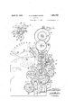
- Fig. 1 is a side elevational view of such ma chine as shown in the said application but .modified so as to disclose the invention which is the subject matter of the present application.
- the casing is removed in the said Fig. 1.
- the ticket after ing mechanism The ticket after ing mechanism.
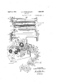
- Fig. 3 is a sectional view on the line 33 of Fig. 1. i
- Fig. 4 is a cross-sectional view through the lower portion of the machine and approxi mately on theline of Fig. 3, and
- Fig. 5 is a perspective view of a part of the gearing which operates the shifting cam shown in Fig. 2. 7
- Fig.2 is a detailed view of the platen shift-
- the machine is provided with side plates 1 and 2.
- the crank handle 3 is mounted on a stub shaft f supported by the side plate 1 and the gear 5 issecured to said stub shaft 4 so that it rotates with the crank handle 8.
- the gear, 5 meshes with a gear 6 mounted on a shaft 7
- The'gear 6 is operatively connected with'a gear 8 provided with ten teeth extending for only a portion of its circumference and with a flange 9 for the remainder of its circumference.
- the gear 8 drives a Geneva gear 10 .whichhas ten teeth. All of these teeth a r'e wide enough to extend over the flange 9 and the teeth on the gear 8. It will be understood, of course.
- the flange 9 is not in the same plane with the teeth on the gear 8.
- the tooth Men the gear 10 is only approximately one-half as long as the re mainder of the teeth so that it will lie in the plane of theteeth on the gear 8 but will extend below the periphery of the flange 9 as shown in Fig. 1.
- the crank handle 3 is rotated clockwise so that the gear 8 is driven anti-clockwise.
- the gear 10 will receive no motion until the gear 8 has rotated to a point so that the upper tooth as shown in Fig. 1 of the gear 8 engages the narrow tooth 11 of the gear 10.
- the gear10 has now rotated in a clockwise.
- the gear lO is secured to a shaft 12 on which is mounted a platen 13.
- the gear 10 meshes with and drives a gear 14 secured to a shaft 15 on which is mounted a platen 16.
- the gear 8 is provided with a wrist pin 17 on which is mounted a pitman 18 which is secured to an oscillating printing carrier 19 by means of a wrist pin 20.
- the oscillating printing carrier 19 is loosely mounted on, a shaft 21.
- Secured to the oscillating printing carrier 19 are two shafts 22 and 23 on which are mounted platens 24 and 25 respectively.
- licket paper 26 isfedfrom a ticket roll not shown, over the platen 24 andbetween the platens 13 and 16.
- Record paper 27 passes over the platen 25. and is conducted to a receiving roll not shown.
- a plurality of levers simllar to the levers 28 shown in Fig. 1 are mounteclon shaft 29.
- the levers 28 are attached to segmental gears 30 which mesh with gears 31 attached to printing wheels 32 mounted on a shaft 33.
- the oscillating printing carrier 19 moves the ticket paper 26 against the printing wheels 32 and thereafter moves the record paper 27 against the same printing wheels soas to make an impression on the top or face of the ticket as well as on the record After the ticket paper has received the impression from the. type wheels 32 it passes between the platens 13 and 16.
- the 'platen16 is provided with an electro-plate 34 which prints the fixed matter on the upper side or face of the ticket. After it has received these two impressions it passes between the blades of a knife 35 which cuts off the ticket from the ticket strip.
- the knife forms no part of this invention and hence is: not described in detail as itis fully shown and described in the application of Robert 13. Long, Serial 8 No. 236,202, filed November 28, 1927. Other than the knife construction :all of the remaining construction thus-far described in detail is shown in the said application ofrllbert S. VVheelbarger and; Grover O. Coil, Serial No. 65,532, filcdOctoberc29, 1925. V 1 H
- One of the levers 28 is adapted to beset to any one of nine positions. 7 In each of itspositions it design tes a different class of fare such as full-fare. half-fare, excursion and anyother classifications which it might be desired to use.
- One of the type wheels 32 is controlled by the class lever.
- the segmental gear 30 connected to the class lever 28 meshes with a pinion 36 mounted on a shaft 37 and is rigidly secured to a gear 38 which meshes with and drives a gear 39 mounted on a shaft 40 andwhich 39 drives a gear 41 which rigidly secured to an indicator 42 which will visually indicate the class of fare which will be registered when the machine is operated.
- the gear 39 also drives a pinion 43 which meshes with and drives a pinion 44 secured to a pinion 45 mounted on a shaft 46.
- the pinion 45 meshes with and drives a gear 47 pivoted on a shaft 48.
- a disk 49 Pivoted on the shaft 48 and secured to a gear 47 is a disk 49 provided with a cutaway portion 50 as shown in 1 and 2. Also secured to disk 49 and gear 47 is a hub 51 provided with a single tooth 52.
- a bell crank lever 53 is pivoted on a shaft 54.
- One arm 55 of the bell crank lever 53 is in the plane of the disk 49 and is adapted either to ride on the periphery of the said disk or to be projected within the cut-away portion 50 thereof, while the ed on a shaft 61 which carries a pinion 62 55 ri idly secured thereto (Figs. 1 and 5) which pinion 62 meshes with and drives a pinion 63 secured to a shaft 64.
- the shaft 64 has secured thereto a Geneva gear 65 and disk 66 which intermittently drives pinions 67, 9'
- each ofwhich pinions is mounted on appropriate shafts.
- the last pinion of the said gear train is operatively connected to a disk 74 by means of a pm 75 and slot 76 connection.
- the electroplate 77 is inked by an ink roller 79 mounted on a shaft 80 carried by a bell crank lever 81 to which is secured a spring 82 which normally urges the ink roller towards the electroplate.
- Fig. 1 the class lever is shown in its eighth position. If it is moved from this position to its ninth position the tooth 52 will engage the arm 56 and the arm 55 will pass into the cutaway portion 50 of the disk 49. This movement of the bell crank lever 53 partially rotates the shaft 85 and the eccentrics 57 so as to lower the platen 59 into contact with the electroplate 77, the platen 59 being held against rotation during this movement by the pin 75 and slot 7 6 connection. If now the machine is operated after the class lever has been placed in its ninth position the gearing shown in Fig. 5 will rotate the electroplate and platen. Since the ticket paper would pass over the electroplate 77 it is obvious that the above described means makes it optional with the operator as to whether or not the machine will print on the bottom of the ticket. The machine prints on the top of the ticket at every operation but will print on both the top and the bottom of the ticket only when the class lever is in a given position.
- the electroplate 77 could contain type to print any printed matter desired such as to print suitable indicia where by the ticket could be used for any predetermined number of going and return trips. /Vhen so used it is obvious that the machine will print a regular ticket of eight difierent classifications and will also print a commutation ticket at the will of the operator.
- the invention might be characterized as a means whereby the operator can print on both sides of a coupon or ticket or only one side.
- a type wheel In a machine, a type wheel, a printing means, manual means whereby said type wheel is rotated and said printing means rendered efi'ective or ineffective and means to indicate whether or not said printing means.
- a manually rotatable gear a disk provided with a cut-away portion operatively connected to said gear, a hub operatively connected to said gear, a tooth carried by said hub, a two-armed lever controlled by said disk and tooth, one of the arms of said lever normally resting on the periphery of said disk, the other arm of said lever normally resting on said hub, the last mentioned arm being adapted to be engaged by said tooth and to rotate the lever so that the arm normally resting on the periphery of said disk will be moved into said cut-away portion thereof, a printing mechanism and means whereby said printing mechanism is rendered operative or inoperative by the movement of said lever.
- a type wheel In a machine, a type wheel, a printing means, means whereby said printing means may be rendered effective or ineifective and manual means whereby said type wheel is rotated when said printing means is rendered effective or inefiective.
- an electroplate and a platen means whereby said platen may be moved out of contact with the electroplate on certain operations of the machine and moved into contact with said electroplate on other operations of the machine, the said electroplate and platen being adapted to print on a strip of paper when said electroplate and platen are in printing engagement and means whereby said strip of paper is held out of contact with said electroplate
Landscapes
- Physics & Mathematics (AREA)
- General Physics & Mathematics (AREA)
- Handling Of Sheets (AREA)
Description
p 1932- A. s WHEELBARGER 7 1 353,792
REGISTER Filed April 7, 1930 2 Sheets-Sheet l /N VE N TOR. AME/P75. WHEELBAFGE/i A TTORNE Y April 12, 1932. A. s. WHEELBARGER REGISTER 2 Sheets-Sheet 2 Filed April '7, 1950 /N\/NTOR. ALBERT 5. WHEELBARG R.
ATTORNEY Patented Apr. 12, 1932 U-Ni'rs ATES,
PATENT mm ALBERT SAMUEL WHEELBARGER, 0F DAYTON, OHITO, ASSIGNOR TOOHMER FARE REGISTER COMPANY, OF DAYTON, OHIO f I REGISTER 2 Application filed April 7, 1930. Serial No. 442,091.
The object of this invention isto provide mechanism in a register so that one side of a ticket or receipt will be printed at each operation of the machine and the other side of the ticket will or will not be printed at the option of the operator. l p
It has heretofore been proposed to have a ticket-issuing machine adapted in particular to issue tickets suitable for transportation 0 purposes. Some of these machines prlnted one or both sides of a ticket. being issued from the machine would be given to the passenger. Some of these tickets were issued singly and certain machines have been made which would issue a plurality of such tickets at one operation or setting of the machine. There is a demand for a machine which will issue the kinds of tickets heretofore used and also a commutation ticket. A
commutation ticket is provided with spaces which the conductor can punch out each time the ticket is used so that the same ticket is good for a number of rides between certain given places. The, object of this inventlon,
therefore, is to provide a machine which will issue a regular ticket having printing on one side and which can also be set so as to print a commutation ticket at the will of the operator.
This is accomplished by printing the commutation part of the ticket onthe reverse side of the ticket on which the printing matter is always printed. v
Broadly speaking, the object of the invention is to provide two printing means, one of 0 which is effective at each operation of the machine and the other of which is effective or not effective at the will of the operator.
I have shown the invention by way of illustration on that class of machine shown in the application of Albert S. Wheelbarger and Grover C. Coil, Serial No. 65,532, filed October 29, 1925.
In the drawin gs Fig. 1 is a side elevational view of such ma chine as shown in the said application but .modified so as to disclose the invention which is the subject matter of the present application. The casing is removed in the said Fig. 1.
The ticket after ing mechanism.
Fig. 3 is a sectional view on the line 33 of Fig. 1. i
Fig. 4 is a cross-sectional view through the lower portion of the machine and approxi mately on theline of Fig. 3, and
Fig. 5 is a perspective view of a part of the gearing which operates the shifting cam shown in Fig. 2. 7
Fig.2 is a detailed view of the platen shift- The machine is provided with side plates 1 and 2. The crank handle 3 is mounted on a stub shaft f supported by the side plate 1 and the gear 5 issecured to said stub shaft 4 so that it rotates with the crank handle 8. The gear, 5 meshes with a gear 6 mounted on a shaft 7 The'gear 6 is operatively connected with'a gear 8 provided with ten teeth extending for only a portion of its circumference and with a flange 9 for the remainder of its circumference. The gear 8 drives a Geneva gear 10 .whichhas ten teeth. All of these teeth a r'e wide enough to extend over the flange 9 and the teeth on the gear 8. It will be understood, of course. that the flange 9 is not in the same plane with the teeth on the gear 8. The tooth Men the gear 10 is only approximately one-half as long as the re mainder of the teeth so that it will lie in the plane of theteeth on the gear 8 but will extend below the periphery of the flange 9 as shown in Fig. 1. The crank handle 3 is rotated clockwise so that the gear 8 is driven anti-clockwise. The gear 10 will receive no motion until the gear 8 has rotated to a point so that the upper tooth as shown in Fig. 1 of the gear 8 engages the narrow tooth 11 of the gear 10. The gear10 has now rotated in a clockwise. direction until all of its ten teeth have meshed with the ten teeth on the gear 8 at which time the tooth to the right of the narrow tooth llas shown in Fig. 1 will again engage the periphery of the flange 9 which will lock the gear 10' against further rotation whilethe gear 8 may continue its rotation; The gear lO is secured to a shaft 12 on which is mounted a platen 13. The gear 10 meshes with and drives a gear 14 secured to a shaft 15 on which is mounted a platen 16.
The gear 8 is provided with a wrist pin 17 on which is mounted a pitman 18 which is secured to an oscillating printing carrier 19 by means of a wrist pin 20. The oscillating printing carrier 19 is loosely mounted on, a shaft 21. Secured to the oscillating printing carrier 19 are two shafts 22 and 23 on which are mounted platens 24 and 25 respectively. licket paper 26 isfedfrom a ticket roll not shown, over the platen 24 andbetween the platens 13 and 16. Record paper 27 passes over the platen 25. and is conducted to a receiving roll not shown.
A plurality of levers simllar to the levers 28 shown in Fig. 1 are mounteclon shaft 29. The levers 28 are attached to segmental gears 30 which mesh with gears 31 attached to printing wheels 32 mounted on a shaft 33. The oscillating printing carrier 19 moves the ticket paper 26 against the printing wheels 32 and thereafter moves the record paper 27 against the same printing wheels soas to make an impression on the top or face of the ticket as well as on the record After the ticket paper has received the impression from the. type wheels 32 it passes between the platens 13 and 16. The 'platen16 is provided with an electro-plate 34 which prints the fixed matter on the upper side or face of the ticket. After it has received these two impressions it passes between the blades of a knife 35 which cuts off the ticket from the ticket strip. ,The knife forms no part of this invention and hence is: not described in detail as itis fully shown and described in the application of Robert 13. Long, Serial 8 No. 236,202, filed November 28, 1927. Other than the knife construction :all of the remaining construction thus-far described in detail is shown in the said application ofrllbert S. VVheelbarger and; Grover O. Coil, Serial No. 65,532, filcdOctoberc29, 1925. V 1 H One of the levers 28 is adapted to beset to any one of nine positions. 7 In each of itspositions it design tes a different class of fare such as full-fare. half-fare, excursion and anyother classifications which it might be desired to use. One of the type wheels 32 is controlled by the class lever. so as to print onthe upper side of the ticket and the record the designated class. The segmental gear 30 connected to the class lever 28 meshes with a pinion 36 mounted on a shaft 37 and is rigidly secured to a gear 38 which meshes with and drives a gear 39 mounted on a shaft 40 andwhich 39 drives a gear 41 which rigidly secured to an indicator 42 which will visually indicate the class of fare which will be registered when the machine is operated. The gear 39 also drives a pinion 43 which meshes with and drives a pinion 44 secured to a pinion 45 mounted on a shaft 46. The pinion 45 meshes with and drives a gear 47 pivoted on a shaft 48. Pivoted on the shaft 48 and secured to a gear 47 is a disk 49 provided with a cutaway portion 50 as shown in 1 and 2. Also secured to disk 49 and gear 47 is a hub 51 provided with a single tooth 52. A bell crank lever 53 is pivoted on a shaft 54. One arm 55 of the bell crank lever 53 is in the plane of the disk 49 and is adapted either to ride on the periphery of the said disk or to be projected within the cut-away portion 50 thereof, while the ed on a shaft 61 which carries a pinion 62 55 ri idly secured thereto (Figs. 1 and 5) which pinion 62 meshes with and drives a pinion 63 secured to a shaft 64. The shaft 64 has secured thereto a Geneva gear 65 and disk 66 which intermittently drives pinions 67, 9'
68, 69, 70, 71, and the double gear 72 which drives the gear 7 3, each ofwhich pinions is mounted on appropriate shafts. The last pinion of the said gear train is operatively connected to a disk 74 by means of a pm 75 and slot 76 connection. I I
When the class lever 28 is moved to any of its first eight positions as indicated in Fig. 1 thearm 56 of the bell crank lever 53 rides on the periphery of the hub 51 and the arm 55 rides on the periphery of the disk 49. When the bell crank lever-53 is in such a position the eccentrics 57 hold the platen 59 elevzitedfrom the electroplate 77 mounted on the shaft 78, which shaft 78carries the said pinion 72 which is intermittently rotated by the gearing shown in Fig. 5 and hereto-fore described. hen the platen 59 and electroplate 77 are separated as they will be in any of the first eight positions of the class lever,
no printing can take place on the lower side of the ticket. The electroplate 77 is inked by an ink roller 79 mounted on a shaft 80 carried by a bell crank lever 81 to which is secured a spring 82 which normally urges the ink roller towards the electroplate.
In Fig. 1 the class lever is shown in its eighth position. If it is moved from this position to its ninth position the tooth 52 will engage the arm 56 and the arm 55 will pass into the cutaway portion 50 of the disk 49. This movement of the bell crank lever 53 partially rotates the shaft 85 and the eccentrics 57 so as to lower the platen 59 into contact with the electroplate 77, the platen 59 being held against rotation during this movement by the pin 75 and slot 7 6 connection. If now the machine is operated after the class lever has been placed in its ninth position the gearing shown in Fig. 5 will rotate the electroplate and platen. Since the ticket paper would pass over the electroplate 77 it is obvious that the above described means makes it optional with the operator as to whether or not the machine will print on the bottom of the ticket. The machine prints on the top of the ticket at every operation but will print on both the top and the bottom of the ticket only when the class lever is in a given position.
It is obvious that the electroplate 77 could contain type to print any printed matter desired such as to print suitable indicia where by the ticket could be used for any predetermined number of going and return trips. /Vhen so used it is obvious that the machine will print a regular ticket of eight difierent classifications and will also print a commutation ticket at the will of the operator.
Broadly speaking, the invention might be characterized as a means whereby the operator can print on both sides of a coupon or ticket or only one side. i
It is necessary to provide some means to keep the ticket strip 26 away from the electroplate 77 when it is desired only to print on the upper side of the ticket and this is accomplished by having a plurality of springs 83 mounted on a bar 84; which springs will press the ticket paper against the platen 59 when said eccentric has been rotated so as to separate said electroplate and platen.
-3. In a machine, a type wheel, a printing means, manual means whereby said type wheel is rotated and said printing means rendered efi'ective or ineffective and means to indicate whether or not said printing means.
will be eilective when the machine is operated.
4. In a machine, a manually rotatable gear, a disk provided with a cut-away portion operatively connected to said gear, a hub operatively connected to said gear, a tooth carried by said hub, a two-armed lever controlled by said disk and tooth, one of the arms of said lever normally resting on the periphery of said disk, the other arm of said lever normally resting on said hub, the last mentioned arm being adapted to be engaged by said tooth and to rotate the lever so that the arm normally resting on the periphery of said disk will be moved into said cut-away portion thereof, a printing mechanism and means whereby said printing mechanism is rendered operative or inoperative by the movement of said lever.
In testimony whereof I aflix my signature.
ALBERT SAMUEL WHEELBARGER.
and will hold the paper away from the electroplate 77 unless the platen 59 and electr- I plate 77 are in printing contact with each other which occurs only when the class lever 28 is in its ninth position. The lever 28 cannot be lowered below its ninth position for if an attempt is made to so move it the arm will engage one of the walls of the cutaway portion 50 and thereby lock the disk 49 against further rotation. Since'the lever 28 is connected to the disk 49 by means of the gearing shown in Fig. 1 the lever 28 is locked against rotation beyond its ninth position.
Having now described my invention by way of illustration, I wish to claim the invention broadly except as I may limit myself in the following claims.
I claim: I
1. In a machine, a type wheel, a printing means, means whereby said printing means may be rendered effective or ineifective and manual means whereby said type wheel is rotated when said printing means is rendered effective or inefiective.
2. In a machine, an electroplate and a platen, means whereby said platen may be moved out of contact with the electroplate on certain operations of the machine and moved into contact with said electroplate on other operations of the machine, the said electroplate and platen being adapted to print on a strip of paper when said electroplate and platen are in printing engagement and means whereby said strip of paper is held out of contact with said electroplate
Publications (1)
| Publication Number | Publication Date |
|---|---|
| US1853792A true US1853792A (en) | 1932-04-12 |
Family
ID=3423661
Family Applications (1)
| Application Number | Title | Priority Date | Filing Date |
|---|---|---|---|
| US1853792D Expired - Lifetime US1853792A (en) | Eegistee |
Country Status (1)
| Country | Link |
|---|---|
| US (1) | US1853792A (en) |
Cited By (1)
| Publication number | Priority date | Publication date | Assignee | Title |
|---|---|---|---|---|
| US2760433A (en) * | 1952-02-27 | 1956-08-28 | Castleton Albert Edward | Rotary printing devices in autographic registers |
-
0
- US US1853792D patent/US1853792A/en not_active Expired - Lifetime
Cited By (1)
| Publication number | Priority date | Publication date | Assignee | Title |
|---|---|---|---|---|
| US2760433A (en) * | 1952-02-27 | 1956-08-28 | Castleton Albert Edward | Rotary printing devices in autographic registers |
Similar Documents
| Publication | Publication Date | Title |
|---|---|---|
| US1208642A (en) | Parcel-postage meter. | |
| US1853792A (en) | Eegistee | |
| US1858813A (en) | Number | |
| US2044367A (en) | Ticket printing, issuing, and accounting machine | |
| US1871060A (en) | Printing device | |
| US2209763A (en) | Cash register | |
| US2104668A (en) | Postage printing and metering | |
| US1370668A (en) | Postage-meter and mail-marking machine | |
| US1265725A (en) | Ticket-printing mechanism. | |
| US1868027A (en) | Class | |
| US1190752A (en) | Adding-machine. | |
| US1960918A (en) | Duplicate ticket receipt register | |
| US1708018A (en) | Printing machine | |
| US1797973A (en) | Machine for applying characters to sheets | |
| US2753790A (en) | Pay roll printing device | |
| US1224813A (en) | Card-making attachment for adding and listing machines. | |
| US3195140A (en) | Locking arrangement for printing apparatus | |
| US1082957A (en) | Apparatus for printing and issuing tickets or checks of different denominations and for registering and totaling numbers and indicating the totals. | |
| USRE15734E (en) | Postage meter and mail-marking machine | |
| US1504277A (en) | Cash register | |
| US1399391A (en) | Slip pbinting and begistebing machine | |
| US769710A (en) | Ticket printing, checking, and recording machine. | |
| US875460A (en) | Ticket-printing machine. | |
| US1038774A (en) | Computing-machine. | |
| US1336693A (en) | fuller |