US1853788A - Conveyer system - Google Patents
Conveyer system Download PDFInfo
- Publication number
- US1853788A US1853788A US578467A US57846731A US1853788A US 1853788 A US1853788 A US 1853788A US 578467 A US578467 A US 578467A US 57846731 A US57846731 A US 57846731A US 1853788 A US1853788 A US 1853788A
- Authority
- US
- United States
- Prior art keywords
- rollers
- parcel
- conveyer
- parcels
- branch
- Prior art date
- Legal status (The legal status is an assumption and is not a legal conclusion. Google has not performed a legal analysis and makes no representation as to the accuracy of the status listed.)
- Expired - Lifetime
Links
- 238000006073 displacement reaction Methods 0.000 description 6
- 230000008602 contraction Effects 0.000 description 3
- 230000000903 blocking effect Effects 0.000 description 1
- 238000007599 discharging Methods 0.000 description 1
- ONKUMRGIYFNPJW-KIEAKMPYSA-N ethynodiol diacetate Chemical compound C1C[C@]2(C)[C@@](C#C)(OC(C)=O)CC[C@H]2[C@@H]2CCC3=C[C@@H](OC(=O)C)CC[C@@H]3[C@H]21 ONKUMRGIYFNPJW-KIEAKMPYSA-N 0.000 description 1
- 230000003116 impacting effect Effects 0.000 description 1
- 239000002674 ointment Substances 0.000 description 1
- 235000002020 sage Nutrition 0.000 description 1
- 238000000926 separation method Methods 0.000 description 1
Images
Classifications
-
- B—PERFORMING OPERATIONS; TRANSPORTING
- B65—CONVEYING; PACKING; STORING; HANDLING THIN OR FILAMENTARY MATERIAL
- B65G—TRANSPORT OR STORAGE DEVICES, e.g. CONVEYORS FOR LOADING OR TIPPING, SHOP CONVEYOR SYSTEMS OR PNEUMATIC TUBE CONVEYORS
- B65G47/00—Article or material-handling devices associated with conveyors; Methods employing such devices
- B65G47/52—Devices for transferring articles or materials between conveyors i.e. discharging or feeding devices
- B65G47/68—Devices for transferring articles or materials between conveyors i.e. discharging or feeding devices adapted to receive articles arriving in one layer from one conveyor lane and to transfer them in individual layers to more than one conveyor lane or to one broader conveyor lane, or vice versa, e.g. combining the flows of articles conveyed by more than one conveyor
- B65G47/681—Devices for transferring articles or materials between conveyors i.e. discharging or feeding devices adapted to receive articles arriving in one layer from one conveyor lane and to transfer them in individual layers to more than one conveyor lane or to one broader conveyor lane, or vice versa, e.g. combining the flows of articles conveyed by more than one conveyor from distinct, separate conveyor lanes
Definitions
- My invention relatesto roller conveyers and has particular reference to a device for.
- roller conveyers it is common practice package or parcel as was accommodated by r either one of the feeder chutes or conveyers so that it is necessary to provide some means at the junction ofthe-feeder chutes to'prevent "collision between the parcels arriving from 7 the different conveyers.
- Another object of my invention is to profor positively stopping parcels on either of the chutes to thereby prevent collision between parcels from different chutes attempting to enter the junction'at the same time.
- I Figure 2 is a bottoniplan viewof the conseparated points, if desired.
- The'conveyer chutes 1 and 2 are illustrated as discharging into a junction 3' whichj'constitutes the entrance of a 'continuation'o'f the :is assumedthat the direction of movement .of parcels upon the conveyer is in the'directi-on ofthe:a-rrowsappearing on, Figure 1. y
- each of the conveyer chutes being provided with a plurality of rollers '5, which may be driven in any suitable manner and which are arranged with their axes substantially parallel to each other and at right angles to'theidirection of s motion of parcels to be conveyed thereoven
- Parcels areprevented from slipping from the rollers 5 as by means of the guiderails 6, 7 and 8, of which rail 7 is indicated in Fig we 1 as constituting a joint rail for both chutes 1 and 2.
- I' Y a substantially funnel-like conveyer, its inner or approaching end 9 being constructed'with a width equal to the sum of the width of the feeder chutes 1 and 2 so that provision is made to permit simultaneous entry of parcels from both of the chutes 1 and 2.
- This junction 3 is also illustrated as being provided with "rollers 10, each of which is mounted 1 and driven similarly to those indicated at 5, but the length of which corresponds substantiallv to the width of'the .conveyer junc tion section.
- rollers 46 and 47 are mounted upon opposite ends of a lever 49, which lever is pivoted at its center 50 to the underneath side of the floor of the conveyer.
- rollers 45 and 48 are mounted at opposite ends of a second lever 51 also pivoted at its center at 50 to the underneath side of the conveyer.
- rollers 52 and 53 are mounted upon opposite ends of a lever 56 pivoted at its center 57 while rollers 53 and 54ers mounted upon opposite ends of a lever 58 pivoted at its center 57.
- rollers 45- -46 pressing of the second parcel on rollers 45- -46 will cause these rollers to separate, allowing the second parcel to enter the junction and at the same time, by reason of the linkage between rollers 45 and 53, the rollers parcel-stop 52 and 53 would be moved into ping position.
- a parcel stopping device for each of said branch conveyers including a pair of levers mounted-upon a common pivot for movement in a plane paral lel to the surface of the associated branch conveyer, a parcel engaging device on each end branch conveyer to cause the corresponding pair on the other conveyer to be moved into parcel stopping position.
- a parcel stoping device for each of said branch conveyers including a pair of levers mounted upon a common pivot for movement in a plane parallel to the surface, of the associated branch conveyer, rollers on each end of each of said levers forming'ther'ewith two pairs of rollers spaced in the direction of movement of parcels on the conveyer and operable by the engagement of a parcel with the first pair to move the levers to withdraw both sets of rollers from parcel stopping-position and operable by the entry of: the parcel between the second pair to hold the engaging devices out of parcel stopping position, and means interconnecting the levers with the stopping devices on both of said branch conveyers for causing movement of oneof the stopping devices out of stopping position to move theother stoppingdevice into stopping position.
- a parcel stopping device for each of said branch conveyers including a pair of levers mounted upon a common pivot for movement in a plane parallel to the surface of the associated branch conveyer, a parcel engaging device on each end of each of said levers forming therewith two pairs of parcel engaging devices spaced in the direction of movementof parcelson the con- 1 V veyer and operable by the engagement of a parcel with the first pair to move the levers to separate said levers and permit the pas sage of a parcel therebetween, and means interconnecting the levers of the stopping de- I vices on both of said branch conveyers to cause separation of the'engaging devices on one
Landscapes
- Engineering & Computer Science (AREA)
- Mechanical Engineering (AREA)
- Branching, Merging, And Special Transfer Between Conveyors (AREA)
Description
H. E. TWOMLEY 1,853,788
CONVEYER SYSTEM April 12, 1932.
Original Filed Feb. 21, 1951 Inventor Patented Apr. 12, 1932 UNiEn STATES PATENT oFricEI HERBERT E. TWOMLEY, 0E RI ERSID CALIFORNIA, ASSIGNOR To CLARA B. TARKER, 0E RIVERSIDE, cALIEo nrA, ExEoU RIx OF THE ESTATE OF GEORGE 1=ARKER,
DECEASED v "CONVEYER SYSTEM -0rigina1 application filed February 21; 1931, Seria1. 1\To.' 517,397. Divided am this application filed December 2, 1931.
My invention relatesto roller conveyers and has particular reference to a device for.
preventing collisions between packages or other articles moving along two separate 5 chutes which terminatein a single opening or continuation of the conveyer system.-
This application is a division of my c0- p ending application Serial No."517,397, filed.
ebruary 21, 1931,
' In roller conveyers it is common practice package or parcel as was accommodated by r either one of the feeder chutes or conveyers so that it is necessary to provide some means at the junction ofthe-feeder chutes to'prevent "collision between the parcels arriving from 7 the different conveyers.
It is, therefore, an object of my invention to provide means for a branchedfconveyer chute to prevent collision between parcels arriving simultaneously at the junction of the chutes. i
Another object of my invention is to profor positively stopping parcels on either of the chutes to thereby prevent collision between parcels from different chutes attempting to enter the junction'at the same time.
vide a branched conveyer chute with means for positively stopping parcels passing along the chutes to prevent collision thereof at the v veyer chute of the roller type, providedwithparcel engaging devices constructed in accordance wlth my invention; and
Ordinarily, the
vide a branched conveyer chute with means Another object of the invention is to pro- Serial No. 578,467. j
I Figure 2 is a bottoniplan viewof the conseparated points, if desired.
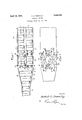
I The'conveyer chutes 1 and 2are illustrated as discharging into a junction 3' whichj'constitutes the entrance of a 'continuation'o'f the :is assumedthat the direction of movement .of parcels upon the conveyer is in the'directi-on ofthe:a-rrowsappearing on, Figure 1. y
The type of con veyer illustrated is that known as aroller conveyer, each of the conveyer chutes being provided with a plurality of rollers '5, which may be driven in any suitable manner and which are arranged with their axes substantially parallel to each other and at right angles to'theidirection of s motion of parcels to be conveyed thereoven Parcels areprevented from slipping from the rollers 5 as by means of the guiderails 6, 7 and 8, of which rail 7 is indicated in Fig we 1 as constituting a joint rail for both chutes 1 and 2. I' Y a substantially funnel-like conveyer, its inner or approaching end 9 being constructed'with a width equal to the sum of the width of the feeder chutes 1 and 2 so that provision is made to permit simultaneous entry of parcels from both of the chutes 1 and 2. This junction 3 is also illustrated as being provided with "rollers 10, each of which is mounted 1 and driven similarly to those indicated at 5, but the length of which corresponds substantiallv to the width of'the .conveyer junc tion section.
.As will be readily apparent'from' an inthese two chutes may extend from-widely conveye'rby way of a continuing chute 1'. i It The-junction 3 is illustrated as comprising into the junction 3, it would be readily apparent that these parcels would engage the guides 11 and 12 and would be brought into contact with each other with the result that the junction 3 would become blocked and thus prevent any of the parcels from passing into the continuin chute 4. To prevent such blocking or jammingof the junction 3, and to prevent collision of the parcels, I have illustrated a stopping device which comprises a pair of rollers and 46 associated with the feeder chute 2, and a corresponding set of rollers 47 and 48 also associated with the feeder chute 2 but spaced from the rollers 45-46 in the direction of motion of the parcelsover the chute.
By referring particularly to Figure 2-, it
will be observed that rollers 46 and 47 are mounted upon opposite ends of a lever 49, which lever is pivoted at its center 50 to the underneath side of the floor of the conveyer. In like manner rollers 45 and 48 are mounted at opposite ends of a second lever 51 also pivoted at its center at 50 to the underneath side of the conveyer. The entry of a parcel from chute 2, impacting the rollers 45 and 46, will move these rollers away from each other to permit the parcel to pass therethrough, while the rollers 47 and 48 will be simultaneously moved apart to permit the passage of the parcel through these rollers.
I Referring again to Figure 1, it will be observed that a similar group of rollers'is associated with chute 1, the rearmost rollers being designated by the reference characters 52 and 53, while the foremost rollers are indicated by the reference characters 54 and 55. Rollers 52 and 55 are mounted upon opposite ends of a lever 56 pivoted at its center 57 while rollers 53 and 54ers mounted upon opposite ends of a lever 58 pivoted at its center 57. The entry of a parcel from chute 1 will cause the rollers 52 and 53 to be moved apart, thus causing a simultaneous displacementof the rollers 54 and 55 By referring particularly to Figure 2, it will be observed that the levers 49 and 56 are connected together at their adjacent ends by means of a link 59, while levers 51 and 58 are similarly connected at their adjacent ends by means of a link 60 so that displacement of rollers 52, 53 causes a corresponding contraction of rollers 45 and 46, or, oppositely,
displacement of rollers 45 or 46 will cause contraction of rollers 52 and 53.
The operation of this form of the device is as follows: A parcel approaching upon chute 1, such as that indicated at 61, will im pact rollers 52 and 53, causing displacement thereof. The displacement of rollers 52 and 53 causes a corresponding displacement of rollers 54 and 55, as hereinbefore described, as well as causing a contraction of rollers 45 and 46 so that the passage from chute 2 is obstructed to prevent the entry of a parcel from this chute to the unct-ion The parcel-which engaged and operated rollers 52 and 53 will pass into the junction and in doing so will enter between rollers 54 and 55 holding these rollers in the position indicated in Figure 1, and thereafter holding rollers 45 and 46 in obstructing positionuntil .the parcel has passed beyond rollers 54 and B s acinmthe sets of rollers 52-53 and in the direction of movement of the parcel, a distance indicated by the'arrow X which is substantially the length of one of the parcels ordinarily conveyed by the sys tem, it will be apparent that before a parcel can enter the junction from the branch conveyer 2, the parcel from chute 1 must have cleared both sets of rollers, thus insuring that theparcel from branch conveyer 2 cannot enter the intersection until there is a sufficient clearance for it.
Assuming that while the first parcel mentioned was passing through the stopping de; 7
vice another parcel on branch conveyer 2 arrived at the junction, it would be stopped by rollers 45-46, though exerting a pressure against these rollers. Thus as soon as the first parcel cleared the rollers -5455, the
pressing of the second parcel on rollers 45- -46 will cause these rollers to separate, allowing the second parcel to enter the junction and at the same time, by reason of the linkage between rollers 45 and 53, the rollers parcel- stop 52 and 53 would be moved into ping position.
On the other hand, assuming that the first parcel mentioned was immediately followed by a second parcel, it would enter the space between rollers 52-53 before the first parcels cleared rollers 54-55, and hence all of the parcels on branch conveyer 1 which were closely spaced, would be permitted to pass before any parcel on branch conveyer 2 would.
While I have illustrated'and described the tinuing conveyer at a junction, a pair of levers, one for each branch conveyer, each lever pivoted for lateral movement beneath the associated branch conveyer, a pair of parcel engaging devices on each lever, one at each end thereof projecting upwardly into the path of parcels on the associated conveyer, the engagement of a parcel by eitherof said parcel engaging devices moving said lever about its pivot to, move the parcel engaging device out of the path of said parcel, and means inter connecting the levers of sai-d two branch conveyers for causing displacement of the parcel engaging device of one branch conveyer to move the parcel engaging device of the other branch conveyer into parcel engaging position. I V
2. In a conveyer system in which a pair of branch conveyers converge into a single continuing conveyerat a junction, a parcel stopping device for each of said branch conveyers including a pair of levers mounted-upon a common pivot for movement in a plane paral lel to the surface of the associated branch conveyer, a parcel engaging device on each end branch conveyer to cause the corresponding pair on the other conveyer to be moved into parcel stopping position. 7
4. In a conveyer system in which a pair of branch conveyers converge into a single continuing conveyer at a junction, a parcel stoping device for each of said branch conveyers including a pair of levers mounted upon a common pivot for movement in a plane parallel to the surface, of the associated branch conveyer, rollers on each end of each of said levers forming'ther'ewith two pairs of rollers spaced in the direction of movement of parcels on the conveyer and operable by the engagement of a parcel with the first pair to move the levers to withdraw both sets of rollers from parcel stopping-position and operable by the entry of: the parcel between the second pair to hold the engaging devices out of parcel stopping position, and means interconnecting the levers with the stopping devices on both of said branch conveyers for causing movement of oneof the stopping devices out of stopping position to move theother stoppingdevice into stopping position.
Signed at Riverside, California, this 24th a day of November, 1931. 1
HERBERTE. TWOMLEY; r
of each of said levers forming therewith two pairs of parcel engaging devices spaced in the Y direction of movement of parcels on the conveyer and parcel with thefirst pair to move the levers to withdraw both setsof rollersfrom parcel operable by the engagement of a stopping position and operable by the entry branch conveyers converge into a single continuing conveyer at a junction, a parcel stopping device for each of said branch conveyers including a pair of levers mounted upon a common pivot for movement in a plane parallel to the surface of the associated branch conveyer, a parcel engaging device on each end of each of said levers forming therewith two pairs of parcel engaging devices spaced in the direction of movementof parcelson the con- 1 V veyer and operable by the engagement of a parcel with the first pair to move the levers to separate said levers and permit the pas sage of a parcel therebetween, and means interconnecting the levers of the stopping de- I vices on both of said branch conveyers to cause separation of the'engaging devices on one
Priority Applications (1)
| Application Number | Priority Date | Filing Date | Title |
|---|---|---|---|
| US578467A US1853788A (en) | 1931-02-21 | 1931-12-02 | Conveyer system |
Applications Claiming Priority (2)
| Application Number | Priority Date | Filing Date | Title |
|---|---|---|---|
| US517397A US1901066A (en) | 1931-02-21 | 1931-02-21 | Conveyer system |
| US578467A US1853788A (en) | 1931-02-21 | 1931-12-02 | Conveyer system |
Publications (1)
| Publication Number | Publication Date |
|---|---|
| US1853788A true US1853788A (en) | 1932-04-12 |
Family
ID=27059133
Family Applications (1)
| Application Number | Title | Priority Date | Filing Date |
|---|---|---|---|
| US578467A Expired - Lifetime US1853788A (en) | 1931-02-21 | 1931-12-02 | Conveyer system |
Country Status (1)
| Country | Link |
|---|---|
| US (1) | US1853788A (en) |
Cited By (1)
| Publication number | Priority date | Publication date | Assignee | Title |
|---|---|---|---|---|
| US3154085A (en) * | 1960-09-02 | 1964-10-27 | Continental Can Co | Sheet or coil cooling tank |
-
1931
- 1931-12-02 US US578467A patent/US1853788A/en not_active Expired - Lifetime
Cited By (1)
| Publication number | Priority date | Publication date | Assignee | Title |
|---|---|---|---|---|
| US3154085A (en) * | 1960-09-02 | 1964-10-27 | Continental Can Co | Sheet or coil cooling tank |
Similar Documents
| Publication | Publication Date | Title |
|---|---|---|
| US3334723A (en) | Transfer conveyor units and control systems therefor | |
| US2612847A (en) | Conveyer system | |
| US3717751A (en) | Counting device for regularly shaped,preferably flat articles,for example,biscuits (or cookies) | |
| WO2009062493A1 (en) | Multiplex grouping device | |
| DE102009040604A1 (en) | Device for distributing beverage crates on e.g. conveyor belt in logistic field, has redirecting handle moved by pneumatic, electric or hydraulic actuated drive and extended from conveyor path in case of straight-line passing of crates | |
| US3465870A (en) | Diverter for conveyor systems | |
| JPH0213510A (en) | Steep inclination belt conveyor device | |
| US3608713A (en) | Skewed roll sortation system | |
| US3506110A (en) | Accumulator | |
| US1853788A (en) | Conveyer system | |
| US3684073A (en) | Conveyor system | |
| US4256214A (en) | System for overhead transport of panel members | |
| US2809741A (en) | Edge-wise conveyor system | |
| US3430951A (en) | Mail sorting letter diverter | |
| US1781424A (en) | Conveying and spacing apparatus | |
| US1901066A (en) | Conveyer system | |
| US1853787A (en) | Conveyer system | |
| US1895046A (en) | Conveyer mechanism | |
| US1763812A (en) | Automatic safety control for conveyers | |
| US1852034A (en) | Conveyer system | |
| US3272298A (en) | Multi-path feed in a conveyor assembly | |
| US2346285A (en) | Conveyer system | |
| US1219900A (en) | Loading mechanism for package-conveyers. | |
| US2847107A (en) | Article selector for conveyor system | |
| US2814378A (en) | Conveying system having diverting means |