US1853781A - Method and apparatus for sheet feeding - Google Patents
Method and apparatus for sheet feeding Download PDFInfo
- Publication number
- US1853781A US1853781A US299215A US29921528A US1853781A US 1853781 A US1853781 A US 1853781A US 299215 A US299215 A US 299215A US 29921528 A US29921528 A US 29921528A US 1853781 A US1853781 A US 1853781A
- Authority
- US
- United States
- Prior art keywords
- sheet
- suction
- stack
- engagement
- sheets
- Prior art date
- Legal status (The legal status is an assumption and is not a legal conclusion. Google has not performed a legal analysis and makes no representation as to the accuracy of the status listed.)
- Expired - Lifetime
Links
- 238000000034 method Methods 0.000 title description 24
- 230000000694 effects Effects 0.000 description 14
- 230000004048 modification Effects 0.000 description 3
- 238000012986 modification Methods 0.000 description 3
- 230000005484 gravity Effects 0.000 description 2
- 239000000463 material Substances 0.000 description 2
- 101150000595 CLMP gene Proteins 0.000 description 1
- 101100382322 Drosophila melanogaster Acam gene Proteins 0.000 description 1
- 229910000831 Steel Inorganic materials 0.000 description 1
- 230000010355 oscillation Effects 0.000 description 1
- 230000000284 resting effect Effects 0.000 description 1
- 238000000926 separation method Methods 0.000 description 1
- 239000010959 steel Substances 0.000 description 1
Images


Classifications
-
- B—PERFORMING OPERATIONS; TRANSPORTING
- B65—CONVEYING; PACKING; STORING; HANDLING THIN OR FILAMENTARY MATERIAL
- B65H—HANDLING THIN OR FILAMENTARY MATERIAL, e.g. SHEETS, WEBS, CABLES
- B65H3/00—Separating articles from piles
- B65H3/08—Separating articles from piles using pneumatic force
- B65H3/12—Suction bands, belts, or tables moving relatively to the pile
- B65H3/124—Suction bands or belts
- B65H3/128—Suction bands or belts separating from the top of pile
Definitions
- My invention relates to a method and apparatus of transporting sheets of paper, or the like, as from a stack thereof, singly and in succession to a desired point.
- suctlon is applied to a sheet to lift it, as from the remainder of a stack of sheets, and during subsequent transportation, as m a rectilinear ath, the sheet is prevented by suctlon from eing acted upon by gravity; more specifically, suction is applied to raise a port1on, as that adjacent an edge of the sheet, and thereafter other suction, preferably supplemented by a blast of air, is effective to move the sheet into engagement with conveying structure, which engagement is maintained, preferably by the last named suction, during transportation of the wrapper.
- the movement of the conveying structure preferably a porous belt in contact with the apertured bottom wall of a suction chamber, is intermittent and the sheets are moved into engagement with belt in a region of suction during intervals in which the belt is stationary.
- My invention further resides in method and apparatus hereinafter described and claimed.
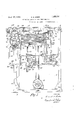
- Fig. 1 is a front elevational view of sheet feeding mechanism embodying my invention.
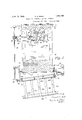
- Fig. 2 is an end elevational view of the mechanism of Fig. 1.
- Fig. 3 is an elevational view of the opposite end of the machine disclosed in Fig. 1.
- Fig. 4 is a top plan view of Fig. 1, with portions broken away to simplify explanation'and description of the mechanism.
- Fig. 5 is a fragmentary side elevational view of parts shown in Figs. 2, 3 and 4.
- Figs. 6 to 12 inclusive are fragmentary views disclosing difierent parts of the mechanism and their position at different points in the cycle of operation.
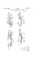
- Figs. 13 to 16 are fragmentary views of a modified form of mechanism, disclosing parts thereof in their various positions during the cycle of operation.
- the shaft 1 of roller 2 is journaled in the end frames 3, 4 integral with or suitably attached to a base member 5 upon which is similarly disposed the end frames 6, 7 lprovided with bearings for supporting the s aft 8 of roller 9.
- a suction chamber 11 Extending substantially the entire distance between the rollers 2 and 9, and supported at its ends, as by attachment to brackets 10 forming part of the end frames, is a suction chamber 11, having a bottom wall of suitable material, as steel, provided with a large number of perforations.
- the interior of the chamber is in communication with a suction pump 12 through pipe 13 extending from the pump and opening into the side of the suction chamber.
- a conveyor belt 120 passes over the rollers 2, 9, with the under surface of the upper portion of the belt resting on the top wall of the suction chamber, and with the upper surface of the lower belt portion in contact with the perforated bottom wall 13 of the suction chamber.
- a gear 15 attached to or integral with a clutch member 16 adapted to engage a co-operating clutch member 17 carried by clutch, collar 18 freely movable longitudinally of shaft 1 but prevented from rotating'relative thereto by key member 19.
- shaft 1 is driven by motor 20 through belt 21, worm 22, worm gear 23, gear 24, rotatable therewith, gear 25, and gear 15.
- gear 24 On the shaft 26 of gear 24 is loosely mounted a member 27 secured in a desired angular relation with respect thereto by bolt 28 whose head portion co-operates with a T -shaped slot in a face of the gear and whose threaded end is engaged by a locking nut 29 to clamp member 27 therebetween and gear 24.
- acam 31 adapted upon rotation of gear 24 to engage a cam roller 32 secured to one end of a pivoted lever 33 whose other end is provided with a yoke 34 engaging and co-operating with clutch collar 18 to effect disengagement between clutch members 16 and 17.
- Reengagement between the clutch members 16 and 17, and a consequent movement of conveyor belt 12a is reestablished upon engagement of the roller 32 b a second cam member 35 which may be as isclosed, secured to a face of gear 24.
- the angular relation between cam members 31 and 35 as fixed by adjustment of member 97 as above described, determines the relative l n hs of the periods of movement and inactivity of belt 12a. It will be understood, however, that insofar as certain aspects of my invention are concerned, the clutch members and their operating mechanism may be dispensed with, and the shaft 1 continuously driven by motor 20.
- a table or plate 36 On a table or plate 36 is disposed a stack of sheets S with the front edges thereof in engagement with a guide plate 37 extending substantially the entire distance between the frame members 3, 4, and secured thereto near its lower edge, as by bolts 38.
- a bifurcated member 39 extends from the lower central portion of plate 37 towards the opposite end of the machine, the leg portions 40 providing bearings for shafts 41 and 42, to the latter of which is secured a gear 43 in meshing en gagement with rack bar 44 extending from and secured to table 36.
- lever 50 pivoted to an extension of frame 6, is mounted an actuatin pawl 51, biased into engagement with ratchet wheel 47 as by a spring 52.' Intermediate its ends, the lever 50 is connected by link rod 53, as is most clearly shown in Figures 10 and 11, to a telltale or feeler lever 54, loosely mounted on shaft 55, and adapted to engage and rest on, at its free end, the top of the stack S. As the sheets are removed from the stack as hereinafter described, the telltale 54 moves downwardly, eventually to an extent causing the actuating pawl 51, to move into engagement with a lower tooth or ratchet wheel 47. Upon upward movement of lever 54, as hereinafter described, ratchet wheel 47 is moved to an extent determined by the extent of depletion of the stack, to cause upward movement of the table 36 through gear train 46, 46, 43 and rack bar 44.
- a supporting structure 58 having free upstanding portions 59 which pass freely through slots 60 in table 36 and which, together with an integral portion 61, engage the front edges of the sheets and form a stop or guide therefor.
- the shaft 55 is journaled in brackets 62 projcctin outwardly from cross piece 61.
- brackets 62 projcctin outwardly from cross piece 61.
- member 63 having a finger 64 adapted upon rotation of shaft 55 to effect upward movement through adjustable screw 65 of telltale lever 54, which as above described is loosely mounted on shaft 55.
- the hollow, sheet lifting arms 66 having a nozzle portion adapted to engage the sheet.
- shaft 74 On one end of shaft 74 is fastened a bevel gear 76 meshing with bevel gear 77 mounted on shaft 78 which is rotatable in a bearing member carried by a bracket 75.
- a bevel gear 79 secured to the other end of the shaft meshes with bevel gear 80 mounted on and adjustable longitudinally of shaft 81 journaled at one end in frame 7 and at the opposite end in a bracket 82 extending from frame 3.
- On one end of shaft 81 On one end of shaft 81 is mounted a bevel gear 83 with which meshes a bevel gear 84 attached to one end of shaft 85 to whose other end is affixed a gear 86 meshing with gear 87 mounted on the same shaft and g rotatable with gear 25.
- the cams 73 Periodically during the continuous rotation of shaft 74 by motor 20, through the connecting mechanism above described, the cams 73 raise the sheet lifting arms 66, having clinging thereto the rear edge of the top sheet of the stack S;
- the suction within chamber 11 is effective to draw the remainder of the sheet into intimate engagementwith the bottom side of conveyor belt 12a.
- this movement of the sheet is effected while the conveyor belt 12a is stationary.
- Return, or downward movement of the lifting arms 66 to engage the next sheet is effected in any suitable manner, as for example, by springs 66 having their ends secured respectively to lifting arms 66 and to an abutment of member 61.
- springs 66 having their ends secured respectively to lifting arms 66 and to an abutment of member 61.
- cam 88 adapted to engage a roller 89 mounted on the end of a valve stem 90 to vary the position of valve member 91 which controls the suction in lifting arms 66.
- cam 88 actuates valve member 91 to destro the suction whereupon movement of the s eet with the conveyor belt in the direction of the arrow is not hindered by lifting members 66.
- a blast of air from nozzles 92 secured to cylinders 93 in each of which is reciprocable a piston valve 94 having a stem 95 to the lower end of which is secured a cam roller 96 engaged by cams 97 secured to and rotatable with shaft 74.
- the air blast is delivered through pipe 98 from the exhaust of pump 67.
- the suc tion thereon is progressively cut oil' as they are carried beyond the end of suction chamber 11, the released portion of the sheet dropping upon a guide plate 101 along which it is pushed by the portion remaining held in contact with the conveyor belt.
- the front edges of the sheets are in turn engaged by the feed rollers 102, 103, the former of which is mounted on the continuously driven shaft 85 and the latter of which is driven thereby through gears 104.
- a plurality of belts 105 engage the peripheries of the lower roller 103, and an idler roll 104, to support and transport the sheets from the feed rolls to a desired destination.
- the machine may be adjusted to feed sheets of various sizes by changing the position of the supporting structure 58 on guide rods 56.
- the stack guiding member 61 is disposed beyond roller 9, and the sheet lifting members are removed from their interposed relation between the conveyor belt 12a and the top of the stack S to permit of closer spacing.
- the suction lifting arms 66 are provided with an elongated, abruptly bent end 66a to engage the top of the stack which is disposed substantially below the top of guide plate 61.
- the telltale lever 54 terminates in an elongated finger 54a which is curved to prevent engagement with plate 61 during its oscillation.
- the method which comprises a plying suction to a portion of a sheet to e ect movement of said portion to a region in which other suction act-s simultaneously upon remaining portions to change the osition of said sheet in its entirety, efiectmg movement of said sheet, and utilizing said other suction to sustain said sheet during said movement.
- the method which comprises applying suction adjacent one edge of a sheet to effect movement thereof to a region in which'other suction acts simultaneously upon the remainder of the sheet to change the position thereof, effecting movement of said sheet, and utilizing said other suction to sustain said sheet during said ture, the method which comprises applying suction to sheets through said structure to hold them in engagement therewith, moving a sheet adjacent said structure while stationary, and utilizing the suction exerted throu' h said structure to complete movement of t 6 sheet into engagement therewith.
- Sheet-feeding means comprising a conveyor member, means intermittently to move said member, and suction means operating in timed relation to said intermittent means and effective while said conveyor is at rest to effect movement of a sheet substantially wholl into engagement with said member.
- gheet-feeding means comprising a conveyor member, means intermittently to move said member, and suction means operating in timed relation to said intermittent means and effective while said conveyor is at rest to effect movement of a sheet substantially wholly into engagement with the under surface of said member and operative to sustain said member during transportation.
- the method which comprises applying suption to a portion of a sheet to effect movement of said portion to a region in which other suction simultaneously acts upon remaining portions to change the position of the sheet in its entirety, and applying air pressure to said sheet to facilitate and assist movement thereof by said other suction.
- the method which comprises exerting suction through said structure, moving a portion of a sheet into engagement therewith, and applying air pressure simultaneously to other portions of the sheet to effect their engagement with said structure.
- the method of moving a sheet perpendicularly into engagement therewith which comprises exerting suction through said structure, and moving a sheet to a region in which the suction acts simultaneously upon a plurality of portions of the sheet to effect its movement into engagement with the foraminous structure.
- the method of moving a sheet substantially perpendicularly into engagement therewith which comprises exerting suction through said structure, and while said conveyor structure .is at rest, moving a sheet to a region. in which the suction acts simultaneously upon a plurality of portions of the sheet to effect its movement into engagement with the conveyor structure.
- the method which comprises moving the top sheet of the stack to a region in which suction simultaneously acts upon a plurality of portions of the sheet to move it substantially wholly in engagement with said structure directly above the stack.
- the method which comprises exerting suction through said structure, and moving a portion of an end sheet of the stack into engagement with said structure, the suction acting simultaneously on remaining portions of the sheet to move it wholly in engagement with said structure substantially directly above the stack.
- the method which comprises exerting suction through said structure, moving a portion of an end sheet of the stack into engagement with said structure, and directing an air blast between the end sheet and the remainder of the stack, the air blast and the suction acting simultaneously on remaining portions of the sheet to move'it wholly in engagement with said structure substantially directly above the stack.
- Sheet-feeding mechanism comprising a foraminous conveyor member, means to exert suction therethrough, sheet supporting structure so disposed that substantially all portions of a sheet carried thereby are simultaneously subject to said suction but to extent insufficient to cause movement, and means to move at least a portion of the sheet to a region in which the suction draws the sheet into engagement with said conveyor.
- Sheet-feeding mechanism comprising an intermittently movable foraminous conveyor member, means exerting suction therethrough, sheet-supporting structure disposed directly below said conveyor member, and suction means operating in timed relation to said conveyor member for moving at least a portion of a sheet adjacent said conveyor member.
- Sheet-feeding mechanism comprising a suction conveyor member, means movable to maintain the end sheet of a stack adj aoent said member and beyond the influence of suction exerted therethrough, adjustable guide structure for engaging an edge of the stack, mechanism carried by said structure and adjustable therewith for controlling said movable means, and mechanism carried by said 1 structure and adjustable therewith for moving the end sheet of said stack toward said suction conveyor member.
- Sheet-feeding mechanism comprising a conveyor, means for supporting astack of sheets, adjustable guide structure for engaging an end of the stack, and mechanism carried by said structure and adjustable therewith for moving the end sheet of the stack toward engagement with said conveyor.
- Sheet-feeding mechanism comprising Q a foraminous conveyor member, means to exert suction therethrough means for supporting a stack of sheets, ad ustable guide structure for engaging an edge of the stack, and mechanism carried by said structure for moving the rear edge of the top sheet of the stack adjacent said conveyor member.
- Sheet-feeding mechanism comprising a foraminous conveyor member, means to exert suction therethrough, structure for supporting a stack of sheets below said conveyor member with the rear edge thereof beyond said conveyor member, and structure movable in a path above said stack and beyond said conveyor for lifting the rear edge of the top sheet of said stack so that the suction draws the remainder thereof into engagement with said conveyor member.
- Sheet-feeding mechanism comprising a foraminous conveyor member, means to exert suction therethrough, guide structure for the rear edges of a stack of sheets disposed beyond said conveyor member, and structure movable between said guide structure and said conveyor for lifting the rear edge of the top sheet of the stack so that the suction draws the remainder thereof into engagement with said conveyor member.
Landscapes
- Engineering & Computer Science (AREA)
- Mechanical Engineering (AREA)
- Sheets, Magazines, And Separation Thereof (AREA)
Description
April 12,, W32. I. E. G. RIDER 3935397831 METHOD AND APPARATUS FOR SHEET FEEDING Filed Aug. 15, 1928 6 Sheets-Sheet l Mi-ELK;
A TTORNE Y.
Aprifi 112, 1932- E. G. RIDER METHOD AND APPARATUS FOR SHEET FEEDING Filed .Aug. 15, 1928 6 Sheets-Sheet 2 A TTORNEY.
April 12, 1932. filDER 1,853,781
METHOD AND APPARATUS FOR SHEET FEEDING Filed Aug. 13, 1928 6 Sheets-Sheet 3 IN V EN TOR.
A TTORNY.
April 12, 1932. E. G. RIDER METHOD AND APPARATUS FOR SHEET FEEDING Filed Aug. 13, 1928 6 Sheets-Sheet 4 5: w 00-05 (IL 0%05 9t: 0% so oowo o o 0 A 0-0 4\ o wo i n 3;: H a N4 m wJyfiw M 2 ATTORNEY.
Aprifi 12, 1932. RlDER 1,853,781
METHOD AND APPARATUS FOR SHEET FEEDING Filed Aug. 13, 1928 6 Sheets-Sheet 5 96 I INVENTOR.
ATTORNEY.
April 12, 1932. E. G. RIDER METHOD AND APPARATUS FOR SHEET FEEDING Filed Aug; 15, 1928 6 Sheets-Sheet 6 INVENTOR- /MQ? fla ATTORNEY.
Patented Apr. 12, 1932 UNITED STATES PATENT OFFICE ERNEST G. RIDER, OF PHILADELPHIA, PENNBYTLVANIA, ASSIGNOR TO STOKES AND SMITH COMPANY, OEPHILADELPHIA, PENNSYLVANIA, A CORPORATION OF PENN- SYLVANIA METHOD AND APPARATUS FOR SHEET FEEDING Application filed August 18, 1928. Serial No. 299,215.
My invention relates to a method and apparatus of transporting sheets of paper, or the like, as from a stack thereof, singly and in succession to a desired point.
In accordance with my invention, suctlon is applied to a sheet to lift it, as from the remainder of a stack of sheets, and during subsequent transportation, as m a rectilinear ath, the sheet is prevented by suctlon from eing acted upon by gravity; more specifically, suction is applied to raise a port1on, as that adjacent an edge of the sheet, and thereafter other suction, preferably supplemented by a blast of air, is effective to move the sheet into engagement with conveying structure, which engagement is maintained, preferably by the last named suction, during transportation of the wrapper.
Furtherin accordance with my invention, and more specifically, the movement of the conveying structure, preferably a porous belt in contact with the apertured bottom wall of a suction chamber, is intermittent and the sheets are moved into engagement with belt in a region of suction during intervals in which the belt is stationary.
My invention further resides in method and apparatus hereinafter described and claimed.
For an illustration of one of the forms my invention may take, reference may be had to the accompanying drawings in which:
Fig. 1 is a front elevational view of sheet feeding mechanism embodying my invention.
Fig. 2 is an end elevational view of the mechanism of Fig. 1.
Fig. 3 is an elevational view of the opposite end of the machine disclosed in Fig. 1.
Fig. 4 is a top plan view of Fig. 1, with portions broken away to simplify explanation'and description of the mechanism.
Fig. 5 is a fragmentary side elevational view of parts shown in Figs. 2, 3 and 4.
Figs. 6 to 12 inclusive are fragmentary views disclosing difierent parts of the mechanism and their position at different points in the cycle of operation.
Figs. 13 to 16 are fragmentary views of a modified form of mechanism, disclosing parts thereof in their various positions during the cycle of operation.
Referring to the drawings, the shaft 1 of roller 2 is journaled in the end frames 3, 4 integral with or suitably attached to a base member 5 upon which is similarly disposed the end frames 6, 7 lprovided with bearings for supporting the s aft 8 of roller 9. Extending substantially the entire distance between the rollers 2 and 9, and supported at its ends, as by attachment to brackets 10 forming part of the end frames, is a suction chamber 11, having a bottom wall of suitable material, as steel, provided with a large number of perforations. The interior of the chamber is in communication with a suction pump 12 through pipe 13 extending from the pump and opening into the side of the suction chamber. A conveyor belt 120; of suitable foraminous material, as canvas or more preferably of rubber having holes punched therethrou h, as disclosed in Stokes Patent No. 1,7 O1,31%, passes over the rollers 2, 9, with the under surface of the upper portion of the belt resting on the top wall of the suction chamber, and with the upper surface of the lower belt portion in contact with the perforated bottom wall 13 of the suction chamber. On an extension of shaft 1, within a housing 14, is loosely mounted a gear 15 attached to or integral with a clutch member 16 adapted to engage a co-operating clutch member 17 carried by clutch, collar 18 freely movable longitudinally of shaft 1 but prevented from rotating'relative thereto by key member 19. During engagement between the clutch member 16 and 17, shaft 1 is driven by motor 20 through belt 21, worm 22, worm gear 23, gear 24, rotatable therewith, gear 25, and gear 15. On the shaft 26 of gear 24 is loosely mounted a member 27 secured in a desired angular relation with respect thereto by bolt 28 whose head portion co-operates with a T -shaped slot in a face of the gear and whose threaded end is engaged by a locking nut 29 to clamp member 27 therebetween and gear 24. To member 27 is suitably secured as by screw 30, acam 31 adapted upon rotation of gear 24 to engage a cam roller 32 secured to one end of a pivoted lever 33 whose other end is provided with a yoke 34 engaging and co-operating with clutch collar 18 to effect disengagement between clutch members 16 and 17. Reengagement between the clutch members 16 and 17, and a consequent movement of conveyor belt 12a is reestablished upon engagement of the roller 32 b a second cam member 35 which may be as isclosed, secured to a face of gear 24. The angular relation between cam members 31 and 35, as fixed by adjustment of member 97 as above described, determines the relative l n hs of the periods of movement and inactivity of belt 12a. It will be understood, however, that insofar as certain aspects of my invention are concerned, the clutch members and their operating mechanism may be dispensed with, and the shaft 1 continuously driven by motor 20.
I On a table or plate 36 is disposed a stack of sheets S with the front edges thereof in engagement with a guide plate 37 extending substantially the entire distance between the frame members 3, 4, and secured thereto near its lower edge, as by bolts 38. A bifurcated member 39 extends from the lower central portion of plate 37 towards the opposite end of the machine, the leg portions 40 providing bearings for shafts 41 and 42, to the latter of which is secured a gear 43 in meshing en gagement with rack bar 44 extending from and secured to table 36. There is also attached to shaft 42, a gear 45 meshing with gear 46, secured on shaft 41, to which is also attached a ratchet gear 47 Downward movement'of table 36, under the influence of gravity, isprevented by a locking pawl 48 biased into engagement with ratchet 47 by spring 49.
On the free end of lever 50, pivoted to an extension of frame 6, is mounted an actuatin pawl 51, biased into engagement with ratchet wheel 47 as by a spring 52.' Intermediate its ends, the lever 50 is connected by link rod 53, as is most clearly shown in Figures 10 and 11, to a telltale or feeler lever 54, loosely mounted on shaft 55, and adapted to engage and rest on, at its free end, the top of the stack S. As the sheets are removed from the stack as hereinafter described, the telltale 54 moves downwardly, eventually to an extent causing the actuating pawl 51, to move into engagement with a lower tooth or ratchet wheel 47. Upon upward movement of lever 54, as hereinafter described, ratchet wheel 47 is moved to an extent determined by the extent of depletion of the stack, to cause upward movement of the table 36 through gear train 46, 46, 43 and rack bar 44.
On rods56, extending between the guide plate 37 and a cross member 57 of the frame having legs 6 and 7, is adjustably mounted a supporting structure 58 having free upstanding portions 59 which pass freely through slots 60 in table 36 and which, together with an integral portion 61, engage the front edges of the sheets and form a stop or guide therefor. The shaft 55, above mentioned, is journaled in brackets 62 projcctin outwardly from cross piece 61. To the sha t 55 between the brackets 62 is secured a member 63 having a finger 64 adapted upon rotation of shaft 55 to effect upward movement through adjustable screw 65 of telltale lever 54, which as above described is loosely mounted on shaft 55.
To the opposite ends of shaft 55, are fixedly attached the hollow, sheet lifting arms 66, having a nozzle portion adapted to engage the sheet. The suction of a pump 67 mounted on a horizontal table portion 68 of the supporting frame 58 and suitably driven as by electric motor 69, acts through pipe 70, hollow shaft 55, and hollow lifting arm 66 to hold the top sheet near its rear edge in contact with the lifting arms, each of which is provided with a downwardly extending ex tension arm 71, having a cam'roller 72, adapted to be engaged by a lifting cam 73, secured to shaft 74 journaled in brackets 75 extending from member 61 of 58. On one end of shaft 74 is fastened a bevel gear 76 meshing with bevel gear 77 mounted on shaft 78 which is rotatable in a bearing member carried by a bracket 75. A bevel gear 79 secured to the other end of the shaft meshes with bevel gear 80 mounted on and adjustable longitudinally of shaft 81 journaled at one end in frame 7 and at the opposite end in a bracket 82 extending from frame 3. On one end of shaft 81 is mounted a bevel gear 83 with which meshes a bevel gear 84 attached to one end of shaft 85 to whose other end is affixed a gear 86 meshing with gear 87 mounted on the same shaft and g rotatable with gear 25. Periodically during the continuous rotation of shaft 74 by motor 20, through the connecting mechanism above described, the cams 73 raise the sheet lifting arms 66, having clinging thereto the rear edge of the top sheet of the stack S;
After certain extent of movement of the arms, the suction within chamber 11 is effective to draw the remainder of the sheet into intimate engagementwith the bottom side of conveyor belt 12a. When the clutch mechanism above described is utilized or operated, this movement of the sheet is effected while the conveyor belt 12a is stationary. Return, or downward movement of the lifting arms 66 to engage the next sheet is effected in any suitable manner, as for example, by springs 66 having their ends secured respectively to lifting arms 66 and to an abutment of member 61. There is also mounted on shaft 74 in proper angular relation to cam 73 the cam 88 adapted to engage a roller 89 mounted on the end of a valve stem 90 to vary the position of valve member 91 which controls the suction in lifting arms 66. After engagement the supporting structure between the top sheet and the conveyor belt has been effected to suitable extent, cam 88 actuates valve member 91 to destro the suction whereupon movement of the s eet with the conveyor belt in the direction of the arrow is not hindered by lifting members 66.
To assist in the separation of the top sheet from the remainder of the stack, there is provided at a proper time and for a suitable interval, a blast of air from nozzles 92 secured to cylinders 93 in each of which is reciprocable a piston valve 94 having a stem 95 to the lower end of which is secured a cam roller 96 engaged by cams 97 secured to and rotatable with shaft 74. The air blast is delivered through pipe 98 from the exhaust of pump 67. When the piston 9& is moved to its upper position, as viewed in Fig. 12, by
As the sheets are carried forward, the suc tion thereon is progressively cut oil' as they are carried beyond the end of suction chamber 11, the released portion of the sheet dropping upon a guide plate 101 along which it is pushed by the portion remaining held in contact with the conveyor belt. The front edges of the sheets are in turn engaged by the feed rollers 102, 103, the former of which is mounted on the continuously driven shaft 85 and the latter of which is driven thereby through gears 104. A plurality of belts 105 engage the peripheries of the lower roller 103, and an idler roll 104, to support and transport the sheets from the feed rolls to a desired destination. The machine may be adjusted to feed sheets of various sizes by changing the position of the supporting structure 58 on guide rods 56.
In a modification of my invention shown in Figs. 13 to 16 inclusive, the stack guiding member 61 is disposed beyond roller 9, and the sheet lifting members are removed from their interposed relation between the conveyor belt 12a and the top of the stack S to permit of closer spacing. In this modification it is possible. in certain instances, to dispense with the air blast. In this modification which has particular advantages when utilized in the feeding of sheets of paper having a strong tendency to curl, the suction lifting arms 66 are provided with an elongated, abruptly bent end 66a to engage the top of the stack which is disposed substantially below the top of guide plate 61. Similarly the telltale lever 54 terminates in an elongated finger 54a which is curved to prevent engagement with plate 61 during its oscillation.
What I claim is:
1. In the art of feeding sheets, the method which comprises a plying suction to a portion of a sheet to e ect movement of said portion to a region in which other suction act-s simultaneously upon remaining portions to change the osition of said sheet in its entirety, efiectmg movement of said sheet, and utilizing said other suction to sustain said sheet during said movement.
2. In the art of feeding sheets, the method which comprises applying suction adjacent one edge of a sheet to effect movement thereof to a region in which'other suction acts simultaneously upon the remainder of the sheet to change the position thereof, effecting movement of said sheet, and utilizing said other suction to sustain said sheet during said ture, the method which comprises applying suction to sheets through said structure to hold them in engagement therewith, moving a sheet adjacent said structure while stationary, and utilizing the suction exerted throu' h said structure to complete movement of t 6 sheet into engagement therewith.
5. Sheet-feeding means comprising a conveyor member, means intermittently to move said member, and suction means operating in timed relation to said intermittent means and effective while said conveyor is at rest to effect movement of a sheet substantially wholl into engagement with said member.
6. gheet-feeding means comprising a conveyor member, means intermittently to move said member, and suction means operating in timed relation to said intermittent means and effective while said conveyor is at rest to effect movement of a sheet substantially wholly into engagement with the under surface of said member and operative to sustain said member during transportation.
7. In a method of feeding sheets, the step of applying suction to a portion of a sheet to effect movement of said portion to a region in which other suction simultaneously acts upon remaining portions to change the position of the sheet in its entirety.
8. In a method of feeding sheets, the step of moving a sheet from a position in which substantially all portions thereof are simultaneously subjected to suction but to extent insufficient to effect movement to a second position from which it is moved by the suction.
9. In the art of feeding sheets by movable structure, the step of moving a sheet from a position in which substantially all portions thereof are simultaneously subjected to suetion but to extent insuflicient to effect movement thereof to a second position from which it is moved into engagement with said movable structure by the suction.
10. In the art of feeding sheets to foraminous structure, the method which comprises exerting suction through said structure, and moving a sheet from a osition in which substantially all portions t ereof are simultaneously subjected to suction but to extent insufficient to effect movement thereof to a second position from which it is moved into engagement with said structure by suction exerted therethrough.. B
11. In the art of feeding sheets, the method which comprises applying suption to a portion of a sheet to effect movement of said portion to a region in which other suction simultaneously acts upon remaining portions to change the position of the sheet in its entirety, and applying air pressure to said sheet to facilitate and assist movement thereof by said other suction.
12. In the art of feeding sheets to foraminous structure, the method which comprises exerting suction through said structure, moving a portion of a sheet into engagement therewith, and applying air pressure simultaneously to other portions of the sheet to effect their engagement with said structure.
13. In the art of feeding sheets to foraminous structure, the method of moving a sheet perpendicularly into engagement therewith which comprises exerting suction through said structure, and moving a sheet to a region in which the suction acts simultaneously upon a plurality of portions of the sheet to effect its movement into engagement with the foraminous structure.
14. In the art of feeding sheets to intermittently movable foraminous conveyor struc ture, the method of moving a sheet substantially perpendicularly into engagement therewith which comprises exerting suction through said structure, and while said conveyor structure .is at rest, moving a sheet to a region. in which the suction acts simultaneously upon a plurality of portions of the sheet to effect its movement into engagement with the conveyor structure.
15. .In the art of feeding sheets to inter mittently movable foraminous conveyor structure, the method of moving a sheet substantially perpendicularly into engagement therewith which comprises exerting suction through said structure, and while said conveyor structure is at rest, moving a sheet to a region in which the suction and an air blast act simultaneously upon a plurality of portions of the sheet to effect its movement into engagement with the conveyor structure.
16. In the art of feeding sheets from a stack and transporting them by movable structure, the method which comprises moving the top sheet of the stack to a region in which suction simultaneously acts upon a plurality of portions of the sheet to move it substantially wholly in engagement with said structure directly above the stack.
17. In the art of feeding sheets from a stack and transporting them by foraminousmovable structure, the method which comprises exerting suction through said structure, and moving a portion of an end sheet of the stack into engagement with said structure, the suction acting simultaneously on remaining portions of the sheet to move it wholly in engagement with said structure substantially directly above the stack.
18. In the art of feeding sheets from a stack and transporting them by foraminous movable structure, the method which comprises exerting suction through said structure, moving a portion of an end sheet of the stack into engagement with said structure, and directing an air blast between the end sheet and the remainder of the stack, the air blast and the suction acting simultaneously on remaining portions of the sheet to move'it wholly in engagement with said structure substantially directly above the stack.
19. Sheet-feeding mechanism comprising a foraminous conveyor member, means to exert suction therethrough, sheet supporting structure so disposed that substantially all portions of a sheet carried thereby are simultaneously subject to said suction but to extent insufficient to cause movement, and means to move at least a portion of the sheet to a region in which the suction draws the sheet into engagement with said conveyor.
20. Sheet-feeding mechanism comprising an intermittently movable foraminous conveyor member, means exerting suction therethrough, sheet-supporting structure disposed directly below said conveyor member, and suction means operating in timed relation to said conveyor member for moving at least a portion of a sheet adjacent said conveyor member. r
21. Sheet-feeding mechanism comprising a suction conveyor member, means movable to maintain the end sheet of a stack adj aoent said member and beyond the influence of suction exerted therethrough, adjustable guide structure for engaging an edge of the stack, mechanism carried by said structure and adjustable therewith for controlling said movable means, and mechanism carried by said 1 structure and adjustable therewith for moving the end sheet of said stack toward said suction conveyor member.
22. Sheet-feeding mechanism comprising a conveyor, means for supporting astack of sheets, adjustable guide structure for engaging an end of the stack, and mechanism carried by said structure and adjustable therewith for moving the end sheet of the stack toward engagement with said conveyor.
23. Sheet-feeding mechanism comprising Q a foraminous conveyor member, means to exert suction therethrough means for supporting a stack of sheets, ad ustable guide structure for engaging an edge of the stack, and mechanism carried by said structure for moving the rear edge of the top sheet of the stack adjacent said conveyor member.
24. Sheet-feeding mechanism comprising a foraminous conveyor member, means to exert suction therethrough, structure for supporting a stack of sheets below said conveyor member with the rear edge thereof beyond said conveyor member, and structure movable in a path above said stack and beyond said conveyor for lifting the rear edge of the top sheet of said stack so that the suction draws the remainder thereof into engagement with said conveyor member.
25. Sheet-feeding mechanism comprising a foraminous conveyor member, means to exert suction therethrough, guide structure for the rear edges of a stack of sheets disposed beyond said conveyor member, and structure movable between said guide structure and said conveyor for lifting the rear edge of the top sheet of the stack so that the suction draws the remainder thereof into engagement with said conveyor member.
ERNEST G. RIDER.
Priority Applications (1)
| Application Number | Priority Date | Filing Date | Title |
|---|---|---|---|
| US299215A US1853781A (en) | 1928-08-13 | 1928-08-13 | Method and apparatus for sheet feeding |
Applications Claiming Priority (1)
| Application Number | Priority Date | Filing Date | Title |
|---|---|---|---|
| US299215A US1853781A (en) | 1928-08-13 | 1928-08-13 | Method and apparatus for sheet feeding |
Publications (1)
| Publication Number | Publication Date |
|---|---|
| US1853781A true US1853781A (en) | 1932-04-12 |
Family
ID=23153819
Family Applications (1)
| Application Number | Title | Priority Date | Filing Date |
|---|---|---|---|
| US299215A Expired - Lifetime US1853781A (en) | 1928-08-13 | 1928-08-13 | Method and apparatus for sheet feeding |
Country Status (1)
| Country | Link |
|---|---|
| US (1) | US1853781A (en) |
Cited By (15)
| Publication number | Priority date | Publication date | Assignee | Title |
|---|---|---|---|---|
| US2619175A (en) * | 1949-03-08 | 1952-11-25 | Harold J Gottlieb | Apparatus for separating carbon sheets from manifold packs |
| US2753795A (en) * | 1950-04-05 | 1956-07-10 | Ditto Inc | Rotary offset duplicating machine |
| US2787467A (en) * | 1953-09-08 | 1957-04-02 | Weber & Co Inc H G | Feeding and takeoff mechanism |
| US2865449A (en) * | 1952-09-26 | 1958-12-23 | Gen Cigar Co | Unwinding and cutting machine for rolled-up ribbons |
| US2977114A (en) * | 1956-08-06 | 1961-03-28 | Pitney Bowes Inc | Document feeding apparatus |
| US2979329A (en) * | 1956-12-24 | 1961-04-11 | Ibm | Paper feeding mechanism |
| US3050175A (en) * | 1959-08-24 | 1962-08-21 | Otto G Jeddeloh | Apparatus for edge spacing structurally stable sheets |
| US3051309A (en) * | 1958-01-03 | 1962-08-28 | Burroughs Corp | Document sorter |
| US3067871A (en) * | 1960-08-05 | 1962-12-11 | Halm Instrument Co | Sorting means |
| US3253824A (en) * | 1964-11-18 | 1966-05-31 | L & L Mfg Inc | Apparatus for separating pieces from a stack, and the like |
| US3885784A (en) * | 1971-01-27 | 1975-05-27 | Thomson Csf | Document singling arrangement |
| US4382593A (en) * | 1980-08-04 | 1983-05-10 | International Business Machines Corporation | Vacuum document feeder |
| US4585335A (en) * | 1979-05-29 | 1986-04-29 | Dainippon Screen Mfg. Co., Ltd. | Automatic process camera |
| US5342035A (en) * | 1992-05-08 | 1994-08-30 | Komori Corporation | Paper feed apparatus for sheet-fed press |
| US6244586B1 (en) * | 1997-11-08 | 2001-06-12 | Ltg Holding Gmbh | Method and apparatus for separating flexible, flat objects |
-
1928
- 1928-08-13 US US299215A patent/US1853781A/en not_active Expired - Lifetime
Cited By (15)
| Publication number | Priority date | Publication date | Assignee | Title |
|---|---|---|---|---|
| US2619175A (en) * | 1949-03-08 | 1952-11-25 | Harold J Gottlieb | Apparatus for separating carbon sheets from manifold packs |
| US2753795A (en) * | 1950-04-05 | 1956-07-10 | Ditto Inc | Rotary offset duplicating machine |
| US2865449A (en) * | 1952-09-26 | 1958-12-23 | Gen Cigar Co | Unwinding and cutting machine for rolled-up ribbons |
| US2787467A (en) * | 1953-09-08 | 1957-04-02 | Weber & Co Inc H G | Feeding and takeoff mechanism |
| US2977114A (en) * | 1956-08-06 | 1961-03-28 | Pitney Bowes Inc | Document feeding apparatus |
| US2979329A (en) * | 1956-12-24 | 1961-04-11 | Ibm | Paper feeding mechanism |
| US3051309A (en) * | 1958-01-03 | 1962-08-28 | Burroughs Corp | Document sorter |
| US3050175A (en) * | 1959-08-24 | 1962-08-21 | Otto G Jeddeloh | Apparatus for edge spacing structurally stable sheets |
| US3067871A (en) * | 1960-08-05 | 1962-12-11 | Halm Instrument Co | Sorting means |
| US3253824A (en) * | 1964-11-18 | 1966-05-31 | L & L Mfg Inc | Apparatus for separating pieces from a stack, and the like |
| US3885784A (en) * | 1971-01-27 | 1975-05-27 | Thomson Csf | Document singling arrangement |
| US4585335A (en) * | 1979-05-29 | 1986-04-29 | Dainippon Screen Mfg. Co., Ltd. | Automatic process camera |
| US4382593A (en) * | 1980-08-04 | 1983-05-10 | International Business Machines Corporation | Vacuum document feeder |
| US5342035A (en) * | 1992-05-08 | 1994-08-30 | Komori Corporation | Paper feed apparatus for sheet-fed press |
| US6244586B1 (en) * | 1997-11-08 | 2001-06-12 | Ltg Holding Gmbh | Method and apparatus for separating flexible, flat objects |
Similar Documents
| Publication | Publication Date | Title |
|---|---|---|
| US1853781A (en) | Method and apparatus for sheet feeding | |
| US2133727A (en) | Delivery mechanism for paper box machines | |
| US3482833A (en) | Sheet feeder assembly | |
| US2639916A (en) | Timed feeding device for carton blanks | |
| US2108702A (en) | Automatic sheet feeding machinery | |
| US3084491A (en) | Means for transporting flexible sheets | |
| US2113650A (en) | Sheet delivery device | |
| US3637448A (en) | Laminating method for honeycomb | |
| US2293046A (en) | Sheet separating mechanism | |
| US1689760A (en) | Apparatus for feeding sheet metal and the like | |
| US3006635A (en) | Method and means for feeding sheets | |
| US1956475A (en) | Blank feeding mechanism | |
| US2240818A (en) | Sheet-feeding mechanism | |
| US2063156A (en) | Folding machine | |
| US2848226A (en) | Sheet-supplying device for printing and paper-working machines | |
| US1840370A (en) | Sheet piling mechanism | |
| US2289501A (en) | Friction stream feeder | |
| US2878629A (en) | Wrapping machines | |
| US1517255A (en) | Sheet-feeding mechanism | |
| US2138995A (en) | Sheet feeder | |
| US1098234A (en) | Paper-feeding machine. | |
| US963946A (en) | Interleaving mechanism. | |
| US1760119A (en) | Paper-feeding machine | |
| US1412404A (en) | Sheet-feeding machine | |
| US751687A (en) | Paper-feeding device |