US1853776A - Grain pan and cutter bar brace - Google Patents
Grain pan and cutter bar brace Download PDFInfo
- Publication number
- US1853776A US1853776A US339234A US33923429A US1853776A US 1853776 A US1853776 A US 1853776A US 339234 A US339234 A US 339234A US 33923429 A US33923429 A US 33923429A US 1853776 A US1853776 A US 1853776A
- Authority
- US
- United States
- Prior art keywords
- frame
- truss
- sub
- arm
- arms
- Prior art date
- Legal status (The legal status is an assumption and is not a legal conclusion. Google has not performed a legal analysis and makes no representation as to the accuracy of the status listed.)
- Expired - Lifetime
Links
- 238000005266 casting Methods 0.000 description 3
- 238000003306 harvesting Methods 0.000 description 3
- 235000007849 Lepidium sativum Nutrition 0.000 description 1
- 244000211187 Lepidium sativum Species 0.000 description 1
- 102100027069 Odontogenic ameloblast-associated protein Human genes 0.000 description 1
- 101710091533 Odontogenic ameloblast-associated protein Proteins 0.000 description 1
- 229910003460 diamond Inorganic materials 0.000 description 1
- 239000010432 diamond Substances 0.000 description 1
- 210000005069 ears Anatomy 0.000 description 1
- 230000002093 peripheral effect Effects 0.000 description 1
- 230000000717 retained effect Effects 0.000 description 1
- 239000000725 suspension Substances 0.000 description 1
Images

Classifications
-
- A—HUMAN NECESSITIES
- A01—AGRICULTURE; FORESTRY; ANIMAL HUSBANDRY; HUNTING; TRAPPING; FISHING
- A01D—HARVESTING; MOWING
- A01D41/00—Combines, i.e. harvesters or mowers combined with threshing devices
- A01D41/12—Details of combines
- A01D41/14—Mowing tables
Definitions
- My invention relates to combined harvesting and threshing machines of the type more fully illustrated in Patent No. 1,7 02,323, is-
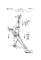
- Fig. 1 is a perspective view of aportion of a combined harvesting and threshing'machine, showing the inner end of the grain pan, sickle bar, and reel broken away to'better illustrate my invention.
- Fig. 2r an enlarged perspective View of the truss members, illustrating their attachment to the frame-work of themachine.
- Fig. 3 is a detail perspective view of. one of the rodtruss fittings for securing one end of the rod truss to the arm carrying the inner end of the sub-frame. 1
- Fig. 4 is a detail perspective view of an end of one of the rod truss members.
- Fig. 5 is a detail perspective view of the bracket for attaching the rod truss to the arm 7 'Thus it will be seenlthat the weight of the carrying the outer end of the sub-frame.
- Fig. 6 is adetail: perspective view of the center strut fitting.
- Fig. 7 is a detail perspective view of the bracket for attaching the outer end of the rod truss to the outer end of the sub-frame.
- a combined harvesting and threshing machine including a separating mechanism indicated by the housing 2 which is carried on a main frame 8 supported by a main traction wheel (not shown) and balanced by a grain wheel 4' that is carried lat- OF INDEPENDENCE, MISSOURI, CORPO- 5 erally of and parallel with the housing 2 by :1
- a lateral frame-work 5 forming part of the main frame.
- the framework 5 includes a channel 6 attached to and extending laterally of the main frame and carries at its free end a vertical channel post 7 supporting a spindle 8 on which the grain wheel is rotatably mounted.
- the channel 6 is suitably braced to the rear of the frame 3 and thevertical channel 7 is connected at its upper end with a similar post 9, adjacent the separator housing by an angle 10 extending parallel with the channel 6.
- the cutting mechanism includes a grain pan 11,- a sickle bar 12 extending along the front edges of the grain pan, a reel 13 and a screw conveyor 14 rotatably mounted in the grain pan for conveying.
- the cut grain to the separator mechanism, and which together 7 with afeeder housing 18 for receiving grain from the conveyor and a threshing element (not shown) adapted to receive grain directly from the feeder housing 18, carried by a subframe 15 ustably mounted on the main frame and preferably consisting of longitudi- Y nal angle members 16, and cross angle members 17 curved to conform to the shape of the "pan and pivotally suspended from the posts 7 and 9 by arms comprising angle bars 19 and 20.
- the arm 19 is pivoted to thepost 9 by a bolt 21 and the bar is pivoted to the post 7 by: a bolt 22 extending through the post 7 and through a bracket 28 at the opposite side of the bar and which is bolted to the post as at 24, the free ends of both arms 19' and 20 being attaohedto the sub-frame 15 carrying the grain pan.
- the truss 27 is of the plate type and com prises triangle members 30 and-3l ha-ving peripheral flanges 32 extending laterally from one side of the web portions 33 and base flanges-34 and35 which aresecured together to provide a substantially diamond shaped truss member.
- Attaching plates 36rand 37are riveted to the respective ends of the web portionof the trussand are provided with .apertured cars 38 and 39 extendingifrom the ends of the truss member, the.ear.3'8being bent forwardly and the ear 39 rearwardlyparallel withthe angle arms 19 and .20 respectively so that the bolt 22 maybe passed through the ear 39 and a bolt 40 on the arm 19 .throughthe ear 38 to secure the truss diagonally between the supporting arms.
- the truss .28, 69-70 includes upper and lower members, the upper member consisting ofrods 41 and 2c-onnectedby a turn buckle 43 by which its length may be adjusted,-.and having eyes 44 at their outer ends vfor connection with the arm 19.and.frame 15 as will presently be described, the rod passing over the truss27 to serve as a strut therefor.
- bracket 46 Fixed to the vertical flange 45 of the supporting: arm 19 and in alignment with the end ofthe uppertrussmember 28 is a bracket 46 comprising .a plate i7 having openings 48 through which bolts 49 are projected to secure the bracket to .the arm, and extending fromrthefface of the :plate arespaced cars 50 fhavingpairsof aligning openingsbl and52.
- The-eye-44 of the :rod 41 is received between the ears and a pin 53 ;is inserted through the "openingsal andthroughtheeyeto secure the end of the .rod't othe arm.
- the end of the other rod 42 is secured by abolt 54to a pairofstraps 55, one at each side of the-rod, with the bolt extending through openings in the straps and through the eye of therod.
- the free ends of the straps adjacent the eye areprovidedwith o fisets 56 for spreading the-straps a 'suflicient distance to receivethe 'sleeveportion 57 of a bracket 58 therebetween.
- the bracket 58 includes a plate 59 having openings60 (Fig. 7 .to receive bolts through the sleeve to secure the straps to the bracket.
- the lower member of the rod truss mem ber comprises pipe sections 69 and 70 having apertured lugs'7l received in the ends of the pipe sections and retained therein by rivets 72 projected through openings 73 in the pipe sections and through aligning openings. 74E in the .lugs.
- the adjoining ends of the pipe'sections are 'hingedly secured to the truss 27 by a casting 7 5 which is'bolted to the lower flanges of the truss 27 by bolts 76 as shown in Figs. 1 and2.
- The-casting is provided with pairs :of cars 77 and 78 extending from opposite sides of he casting and having openings therein for fastening devices which are projected through the openings and through the apertures of the lugs 71 to secure the pipe sections to thetruss 27.. l
- the outer end of the section 69 is secured to the bracket 46011 arm 19 by awpin 79 pro jected through'the'lug'71 and through-the ilower pair of openings 52 in thebracket 46 and the'outcr endof'the section 70 is pivoted on apin 80extending through thest-raps '55 adjacent the bracket 58 on a cross member 17 of thebracket 15.
- This section of the truss is also connected with the angle arm 20'by an L shaped bracket81-depending from the arm, the horizontal portion'82 of the bracket being secured to the truss section by ,a U bolt 83 and the'vertical portion84: adjustably fixed to the arm by a bolt 85 extending through an opening in the arm and a slot 86 in the bracket.
- the turnbuckle t3 is adjusted to lift or lower the outer end of the grain pan until the pan is level and at right anglesto the mainframe of the machine. Should the grain pan sag or become loose, it may be readlly straight 'ened or tightened by adjusting the turnbuckle.
- a machine of the character described including a main frame, paired arms pivoted to the main frame, a sub-frame supported by said arms, a truss connecting one of the arms adjacent its pivot with an end of the subframe, a second truss having flexible connections with the other arm and with the opposite end of the sub-frame, and means for tensioning the last named truss to level'the subframe.
- a main frame a sub-frame, arms pivotally suspending the sub-frame from the main frame, a diagonal truss pivotally mounted on the main frame coaxially with one of the arms and pivotally attached to the other arm near the forward end thereof, and a cross truss fiexibly connecting the last mentioned arm with the sub-frame to permit adjustment of the sub-frame.
- a main frame In a machine of the character described, a main frame, a sub-frame, arms pivotally suspending the sub-frame from the main frame, a diagonal truss pivotally mounted on the main frame coaxially with one of the arms and attached to the other arm near the forward end thereof, and a cross truss flexibly connecting the last mentioned arm with the sub-frame, the cross truss being adjustable for leveling the sub-frame with the main frame.
- amain frame pivotally suspending the sub-frame from the main frame
- a diagonal truss pivotally mounted on the main frame coaxially with one of the arms and attached to the other armnear the forward end thereof
- a cross truss pivotally connected with the last mentioned arm and with the sub-frame and seated on the diagonal truss.
- a main frame pivotally suspending the sub-frame from the main frame, a diagonal truss pivotally mounted 011 the main frame coaxially with one of the arms and attached to the other arm near the forward end thereof, and an adjustable cross truss pivotally connected with the last mentioned arm and with the sub-frame and seated on the diagonal truss.
- a main frame a sub-frame, arms pivotally suspending the sub-frame from the main.
- a diagonal truss pivotally mounted on the main frame coaxially with one of the arms and attached to the other arm near the forward end thereof, and a cross truss including a primary member having flexible connections with the last mentioned arm'and withthe sub-frame and seated on'the diagonal truss and a secondary member including sections connecting the lower edge of the diagonal trussrespectively-with the said last mentioned arm and with the primary member.
- .ajmain frame a sub-frame, arms pivotally suspending the sub-frame from the main frame, a diagonal truss pivotally mounted on the mainframe coaxially with the pivot point of-one of the arms and cooperating with the other arm in supporting the subframe, across truss including a primarymember'havmg fleXlblGCOIlIlQCtlOnS with the 1 last mentionedarm and with the sub-frame and seated on the diagonal truss, and a secondary member including sections pivotally connected with the last mentioned arm and the truss and with the truss and the primary member respectively, and means for adjusting the primary member to level the subframe.
- a main frame pivotally suspending the sub-frame from the main frame
- a diagonal truss pivotally mounted on the mainframe coaxially with one of the arms and cooperating with the other arm for supporting the sub-frame
- a cross truss including a primary member having flexible connections with the last mentioned arm and having bearing on the diagonal truss, a strap member pivoted to the subframe and pivotally connected to the primary member, a secondary member including sections connecting the lower edge of the diagonal truss respectively with the last mentioned arm and with the strap member, and means for tensioning the primary member to level the sub-frame.
- a main frame a sub-frame, arms pivotally suspending the sub-frame from the main frame, a diagonal truss pivotally mounted on the main frame coaxially with the pivot,
- a cross truss including a primary member having pivotal connection with the lastmentioned arm and having bearing on the diagonal truss, strap members pivoted to the sub-,frame and pivotally connected with the primary member, a secondary member including sections connecting the lower edge of the diagonal truss respectively with 4 1;sname the last mentioned arm and with the strap members intermetfiate their ends, rand. -means ferttensionimg the primary member to level the. sub-frame.
- a main frame In a machine. of the character described, a main frame, a sub-frame, arms pivotaliy suspending the sub-frame from the main frame, a truss member extendingdiagonally between the arms and cooperating therewith to support the sub-frame,sa cross truss havingflexible connections with one of the arms and with the sub-frame, :and means for tensioning the-cross truss to level the P sub-frame.
Landscapes
- Life Sciences & Earth Sciences (AREA)
- Environmental Sciences (AREA)
- Jib Cranes (AREA)
Description
April 12, 1932.
T. N. PIERSON GRAIN PAN AND CUTTER BAR BRACE 11, 1929 2 Sheets-Sheet INVENTOR 70/ra/d/l/ 96/60/21 BY Y ATTORNEY \Filed Feb.
April 12, 1932. T. N. PIERSON I GRAIN PAN AND CUTTER BAR BRACE Filed Feb. 11, 1929 2 Sheets-Sheet INVENTOR 70/m/o A! l m/J0. Y
' )ATTORNEY' Patented Apr. 12, 1932 u iTsD STATES PATENT orFicE TORVA LD N. PIERSON, OE INDEPENDENCE, MISSOURI, ASSIGNOR TO THE GLEANER COMBINE HARVESTER CORPORATION, RATION I GRAIN PAN AND CUTTER BAR BRAGE Application filed February 11 1929. Serial No. 339,234. I
My invention relates to combined harvesting and threshing machines of the type more fully illustrated in Patent No. 1,7 02,323, is-
It is also a further object of the invention to provide a support that may be readily adjusted for aligning the sub-frame. 1
In accomplishing-these and other objects of the invention, I have provided improved details of structure, the preferred forms of which are illustrated in the accompanying drawings, wherein:
Fig. 1 is a perspective view of aportion of a combined harvesting and threshing'machine, showing the inner end of the grain pan, sickle bar, and reel broken away to'better illustrate my invention. r
Fig. 2ris an enlarged perspective View of the truss members, illustrating their attachment to the frame-work of themachine.
Fig. 3 is a detail perspective view of. one of the rodtruss fittings for securing one end of the rod truss to the arm carrying the inner end of the sub-frame. 1
Fig. 4: is a detail perspective view of an end of one of the rod truss members.
Fig. 5 is a detail perspective view of the bracket for attaching the rod truss to the arm 7 'Thus it will be seenlthat the weight of the carrying the outer end of the sub-frame.
Fig. 6 is adetail: perspective view of the center strut fitting.
Fig. 7 is a detail perspective view of the bracket for attaching the outer end of the rod truss to the outer end of the sub-frame.
Referring in detail to the drawings:
1 designates a combined harvesting and threshing machine including a separating mechanism indicated by the housing 2 which is carried on a main frame 8 supported by a main traction wheel (not shown) and balanced by a grain wheel 4' that is carried lat- OF INDEPENDENCE, MISSOURI, CORPO- 5 erally of and parallel with the housing 2 by :1
a lateral frame-work 5 forming part of the main frame.
The framework 5 includesa channel 6 attached to and extending laterally of the main frame and carries at its free end a vertical channel post 7 supporting a spindle 8 on which the grain wheel is rotatably mounted. The channel 6 is suitably braced to the rear of the frame 3 and thevertical channel 7 is connected at its upper end with a similar post 9, adjacent the separator housing by an angle 10 extending parallel with the channel 6. I,
The cutting mechanism includes a grain pan 11,- a sickle bar 12 extending along the front edges of the grain pan, a reel 13 and a screw conveyor 14 rotatably mounted in the grain pan for conveying. the cut grain to the separator mechanism, and which together 7 with afeeder housing 18 for receiving grain from the conveyor and a threshing element (not shown) adapted to receive grain directly from the feeder housing 18, carried by a subframe 15 ustably mounted on the main frame and preferably consisting of longitudi- Y nal angle members 16, and cross angle members 17 curved to conform to the shape of the "pan and pivotally suspended from the posts 7 and 9 by arms comprising angle bars 19 and 20. The arm 19 is pivoted to thepost 9 by a bolt 21 and the bar is pivoted to the post 7 by: a bolt 22 extending through the post 7 and through a bracket 28 at the opposite side of the bar and which is bolted to the post as at 24, the free ends of both arms 19' and 20 being attaohedto the sub-frame 15 carrying the grain pan.
entire grain cutting and threshing mechanism is carriedat the free ends ofthe angle arms 19 and 20 and that the weight must necessarily be suspended from the main frame ineluding the lateral frame-work 5 This suspension is effected by the arms 19 and 20 in conjunction with counterbalance springs operating parts by twist and sag of the grain pan when the machine is in operation, I provide crossed trusses 27 and 28, 6970 one of which is connected with the bracket 23 on the post 7 by the bolt .22, whereby the Farm 20 is pivotally mounted on the pan, andwith the arm 19 at a point adjacent its connection with the grain pan, and the other with an inner portion of the arm 19 and with the outer end of the frame 15. i
The truss 27 is of the plate type and com prises triangle members 30 and-3l ha-ving peripheral flanges 32 extending laterally from one side of the web portions 33 and base flanges-34 and35 which aresecured together to provide a substantially diamond shaped truss member.
Attaching plates 36rand 37are riveted to the respective ends of the web portionof the trussand are provided with .apertured cars 38 and 39 extendingifrom the ends of the truss member, the.ear.3'8being bent forwardly and the ear 39 rearwardlyparallel withthe angle arms 19 and .20 respectively so that the bolt 22 maybe passed through the ear 39 and a bolt 40 on the arm 19 .throughthe ear 38 to secure the truss diagonally between the supporting arms.
The truss .28, 69-70 includes upper and lower members, the upper member consisting ofrods 41 and 2c-onnectedby a turn buckle 43 by which its length may be adjusted,-.and having eyes 44 at their outer ends vfor connection with the arm 19.and.frame 15 as will presently be described, the rod passing over the truss27 to serve as a strut therefor.
Fixed to the vertical flange 45 of the supporting: arm 19 and in alignment with the end ofthe uppertrussmember 28 is a bracket 46 comprising .a plate i7 having openings 48 through which bolts 49 are projected to secure the bracket to .the arm, and extending fromrthefface of the :plate arespaced cars 50 fhavingpairsof aligning openingsbl and52.
The-eye-44 of the :rod 41 is received between the ears and a pin 53 ;is inserted through the "openingsal andthroughtheeyeto secure the end of the .rod't othe arm. The end of the other rod 42 is secured by abolt 54to a pairofstraps 55, one at each side of the-rod, with the bolt extending through openings in the straps and through the eye of therod.
The free ends of the straps adjacent the eye areprovidedwith o fisets 56 for spreading the-straps a 'suflicient distance to receivethe 'sleeveportion 57 of a bracket 58 therebetween. The bracket 58 includes a plate 59 having openings60 (Fig. 7 .to receive bolts through the sleeve to secure the straps to the bracket.
The upper truss member 28, formed by the rods 41 and 42, extends across the apex of the truss 27 and rests in a saddle 6a fixed to the top flanges of the truss 27 and comprising a plate portion having integral spaced lugs 66 projecting therefrom to provide a seat 67 for receiving the rod member, thesaddle beingbolted tothe flange of the trussbybolts 68.
The lower member of the rod truss mem ber comprises pipe sections 69 and 70 having apertured lugs'7l received in the ends of the pipe sections and retained therein by rivets 72 projected through openings 73 in the pipe sections and through aligning openings. 74E in the .lugs.
The adjoining ends of the pipe'sections are 'hingedly secured to the truss 27 by a casting 7 5 which is'bolted to the lower flanges of the truss 27 by bolts 76 as shown in Figs. 1 and2. The-casting is provided with pairs :of cars 77 and 78 extending from opposite sides of he casting and having openings therein for fastening devices which are projected through the openings and through the apertures of the lugs 71 to secure the pipe sections to thetruss 27.. l
The outer end of the section 69 is secured to the bracket 46011 arm 19 by awpin 79 pro jected through'the'lug'71 and through-the ilower pair of openings 52 in thebracket 46 and the'outcr endof'the section 70 is pivoted on apin 80extending through thest-raps '55 adjacent the bracket 58 on a cross member 17 of thebracket 15. This section of the truss is also connected with the angle arm 20'by an L shaped bracket81-depending from the arm, the horizontal portion'82 of the bracket being secured to the truss section by ,a U bolt 83 and the'vertical portion84: adjustably fixed to the arm by a bolt 85 extending through an opening in the arm and a slot 86 in the bracket. V
In aligning 'the cutting :mechanism the turnbuckle t3=is adjusted to lift or lower the outer end of the grain pan until the pan is level and at right anglesto the mainframe of the machine. Should the grain pan sag or become loose, it may be readlly straight 'ened or tightened by adjusting the turnbuckle.-
1t will be notedthat the tensionlng ofzthe truss does not apply strain to the frame work of the machine since the trusses are pivotally mounted at their ends and readily adjust themselves without straining their connections to the'frame work.
What I claim and desire to secure by Letters Patent'is the sub frame from the main frame, one of said trusses crossing the other and comprismentioned arm and with the primary member.
ing flexibly connected rods, and means for adjusting the rods to tension the truss.
2. In a machine of the character described including a main frame, paired arms pivoted to the main frame, a sub-frame supported by said arms, a truss connecting one of the arms adjacent its pivot with an end of the subframe, a second truss having flexible connections with the other arm and with the opposite end of the sub-frame, and means for tensioning the last named truss to level'the subframe.
3. In a machine of the character described,
a main frame, a sub-frame, arms pivotally suspending the sub-frame from the main frame, a diagonal truss pivotally mounted on the main frame coaxially with one of the arms and pivotally attached to the other arm near the forward end thereof, and a cross truss fiexibly connecting the last mentioned arm with the sub-frame to permit adjustment of the sub-frame.
4:. In a machine of the character described, a main frame, a sub-frame, arms pivotally suspending the sub-frame from the main frame, a diagonal truss pivotally mounted on the main frame coaxially with one of the arms and attached to the other arm near the forward end thereof, and a cross truss flexibly connecting the last mentioned arm with the sub-frame, the cross truss being adjustable for leveling the sub-frame with the main frame.
5. In a machine of the character described, amain frame, a sub-frame, arms pivotally suspending the sub-frame from the main frame, a diagonal truss pivotally mounted on the main frame coaxially with one of the arms and attached to the other armnear the forward end thereof, and a cross truss pivotally connected with the last mentioned arm and with the sub-frame and seated on the diagonal truss.
6. In a machine of the character described, a main frame, a sub-frame, arms pivotally suspending the sub-frame from the main frame, a diagonal truss pivotally mounted 011 the main frame coaxially with one of the arms and attached to the other arm near the forward end thereof, and an adjustable cross truss pivotally connected with the last mentioned arm and with the sub-frame and seated on the diagonal truss.
7. In a machine of the character described,
8. Ina machine of the character-described, a main frame, a sub-frame, arms pivotally suspending the sub-frame from the main.
frame, a diagonal truss pivotally mounted on the main frame coaxially with one of the arms and attached to the other arm near the forward end thereof, and a cross truss including a primary member having flexible connections with the last mentioned arm'and withthe sub-frame and seated on'the diagonal truss and a secondary member including sections connecting the lower edge of the diagonal trussrespectively-with the said last mentioned arm and with the primary member.
9. In a machine of the character described,
.ajmain frame, a sub-frame, arms pivotally suspending the sub-frame from the main frame, a diagonal truss pivotally mounted on the mainframe coaxially with the pivot point of-one of the arms and cooperating with the other arm in supporting the subframe, across truss including a primarymember'havmg fleXlblGCOIlIlQCtlOnS with the 1 last mentionedarm and with the sub-frame and seated on the diagonal truss, and a secondary member including sections pivotally connected with the last mentioned arm and the truss and with the truss and the primary member respectively, and means for adjusting the primary member to level the subframe.
].0. In a machine of the character described, a main frame, a sub-frame, arms pivotally suspending the sub-frame from the main frame, a diagonal truss pivotally mounted on the mainframe coaxially with one of the arms and cooperating with the other arm for supporting the sub-frame, a cross truss including a primary member having flexible connections with the last mentioned arm and having bearing on the diagonal truss, a strap member pivoted to the subframe and pivotally connected to the primary member, a secondary member including sections connecting the lower edge of the diagonal truss respectively with the last mentioned arm and with the strap member, and means for tensioning the primary member to level the sub-frame.
11. In a machine of the character described a main frame, a sub-frame, arms pivotally suspending the sub-frame from the main frame, a diagonal truss pivotally mounted on the main frame coaxially with the pivot,
point of one of the arms and cooperating with the other arm in supporting the subframe, a cross truss including a primary member having pivotal connection with the lastmentioned arm and having bearing on the diagonal truss, strap members pivoted to the sub-,frame and pivotally connected with the primary member, a secondary member including sections connecting the lower edge of the diagonal truss respectively with 4 1;sname the last mentioned arm and with the strap members intermetfiate their ends, rand. -means ferttensionimg the primary member to level the. sub-frame.
12., In a machine of the character described amai-n frame, ,a suhfirame, arms pivetally suspending the sub-frame iirom the mainframe, a diagonal truss pi-votally mounted on the main. frame 'coaXiaH-y with one of the :arms and cooperating with the other arm in supporting the sub-frame, a CI'OSS truss flexibly connecting the last mentiened :arm with the sub-frame, and means for .tensioning'the .cress' truss for level'ingthe sub-framewith relation to the main trame.
13; In a machine. of the character described, a main frame, a sub-frame, arms pivotaliy suspending the sub-frame from the main frame, a truss member extendingdiagonally between the arms and cooperating therewith to support the sub-frame,sa cross truss havingflexible connections with one of the arms and with the sub-frame, :and means for tensioning the-cross truss to level the P sub-frame.
In testimony whereof I aflix my signature.
TORVALD N. PIERSON.
Priority Applications (1)
| Application Number | Priority Date | Filing Date | Title |
|---|---|---|---|
| US339234A US1853776A (en) | 1929-02-11 | 1929-02-11 | Grain pan and cutter bar brace |
Applications Claiming Priority (1)
| Application Number | Priority Date | Filing Date | Title |
|---|---|---|---|
| US339234A US1853776A (en) | 1929-02-11 | 1929-02-11 | Grain pan and cutter bar brace |
Publications (1)
| Publication Number | Publication Date |
|---|---|
| US1853776A true US1853776A (en) | 1932-04-12 |
Family
ID=23328090
Family Applications (1)
| Application Number | Title | Priority Date | Filing Date |
|---|---|---|---|
| US339234A Expired - Lifetime US1853776A (en) | 1929-02-11 | 1929-02-11 | Grain pan and cutter bar brace |
Country Status (1)
| Country | Link |
|---|---|
| US (1) | US1853776A (en) |
-
1929
- 1929-02-11 US US339234A patent/US1853776A/en not_active Expired - Lifetime
Similar Documents
| Publication | Publication Date | Title |
|---|---|---|
| US3880241A (en) | Multiple-piece wing sections for cultivator and oscillation preventing device for same | |
| US4095815A (en) | Racing sulky | |
| US2320624A (en) | Disk harrow | |
| US2717479A (en) | Disk harrow frame adjustment | |
| US4329833A (en) | Self-propelled harvesting combine | |
| US2498888A (en) | Winged cultivator | |
| US5000268A (en) | Lifting assembly for agricultural implements | |
| US1853776A (en) | Grain pan and cutter bar brace | |
| US5033257A (en) | Conditioner roll tension system | |
| US3159959A (en) | Antiscalping suspension for rotary hay cutter | |
| US2298161A (en) | Cultivator | |
| KR102555574B1 (en) | Soil moving apparatus for rotavator | |
| US2259892A (en) | Tractor mounted corn picker and husker | |
| US1906606A (en) | Adjustable offset hitch | |
| CA1150559A (en) | Articulated plow with central support providing counter moment for rear section | |
| US3066465A (en) | Front mounted end to end arranged double mower | |
| US2160350A (en) | Drawbar | |
| US1670270A (en) | Tractor-supported plowing attachment | |
| US2645073A (en) | Mower mounting | |
| US1936613A (en) | Combine | |
| US1555887A (en) | Ensilage cutter | |
| US2143193A (en) | Disk bedder | |
| US3646732A (en) | Free-cutting mowing machine | |
| US2337104A (en) | Road scraper attachment for tractors | |
| US1706617A (en) | Combination harvester thrasher |