US1853770A - Flexible power transmission device - Google Patents
Flexible power transmission device Download PDFInfo
- Publication number
- US1853770A US1853770A US404137A US40413729A US1853770A US 1853770 A US1853770 A US 1853770A US 404137 A US404137 A US 404137A US 40413729 A US40413729 A US 40413729A US 1853770 A US1853770 A US 1853770A
- Authority
- US
- United States
- Prior art keywords
- axle
- link
- metallic
- plates
- shaped member
- Prior art date
- Legal status (The legal status is an assumption and is not a legal conclusion. Google has not performed a legal analysis and makes no representation as to the accuracy of the status listed.)
- Expired - Lifetime
Links
- 230000005540 biological transmission Effects 0.000 title description 9
- 239000000126 substance Substances 0.000 description 17
- 239000000428 dust Substances 0.000 description 9
- 230000008878 coupling Effects 0.000 description 6
- 238000010168 coupling process Methods 0.000 description 6
- 238000005859 coupling reaction Methods 0.000 description 6
- 239000007787 solid Substances 0.000 description 3
- 244000286663 Ficus elastica Species 0.000 description 2
- RRHGJUQNOFWUDK-UHFFFAOYSA-N Isoprene Chemical compound CC(=C)C=C RRHGJUQNOFWUDK-UHFFFAOYSA-N 0.000 description 2
- 239000000835 fiber Substances 0.000 description 2
- 239000011796 hollow space material Substances 0.000 description 2
- 239000010985 leather Substances 0.000 description 2
- 238000005461 lubrication Methods 0.000 description 2
- 229910052751 metal Inorganic materials 0.000 description 2
- 229920001195 polyisoprene Polymers 0.000 description 2
- 229910052729 chemical element Inorganic materials 0.000 description 1
- 238000010276 construction Methods 0.000 description 1
- 230000001050 lubricating effect Effects 0.000 description 1
- 239000000463 material Substances 0.000 description 1
- 229910052755 nonmetal Inorganic materials 0.000 description 1
Images
Classifications
-
- F—MECHANICAL ENGINEERING; LIGHTING; HEATING; WEAPONS; BLASTING
- F16—ENGINEERING ELEMENTS AND UNITS; GENERAL MEASURES FOR PRODUCING AND MAINTAINING EFFECTIVE FUNCTIONING OF MACHINES OR INSTALLATIONS; THERMAL INSULATION IN GENERAL
- F16G—BELTS, CABLES, OR ROPES, PREDOMINANTLY USED FOR DRIVING PURPOSES; CHAINS; FITTINGS PREDOMINANTLY USED THEREFOR
- F16G5/00—V-belts, i.e. belts of tapered cross-section
- F16G5/16—V-belts, i.e. belts of tapered cross-section consisting of several parts
- F16G5/18—V-belts, i.e. belts of tapered cross-section consisting of several parts in the form of links
Definitions
- the invention has for its object a flexible power transmission device.
- the apparatus differs from the i0 preceding, by the fact that the pivoted joint between means of a metallic element and a non-metaL lic element which latter has a great strength and is not subject to traction.
- the accompanying drawings show by way of example an embodiment of the invention.
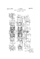
- Figure 1 is a partial view of the apparatus, which is partly in section.
- Figure 2 is aside view of a set of members according to Figure 1, viewed from right to left. j
- Figure 3 is a section of the apparatus shown in Figure 1, viewed from right to left.
- Figure 4 isa plan view corresponding to Figure 1,'partly in section.
- Figures 5 to 9 show various details.
- Each of the members 1-2-3-4 which is subject to pressure, has a general trapezoidal g cross-section, and comprises a set of vplates 5--6-7-8-9 placed in contact and consisting of leather or india rubber.
- In each of said members is a hollow space lOextencling in the transverse direction from one end of said member to the other and of which the cross section is square.
- each member comprises'a U-shapedpiece 40 having flanges 41 at one end, and also two plates 42, having on one of their respective ends a half-round part 43, and on the other l bent part 44.
- the said half-round part 43 is further from the middle plane of the said member than the plate 42,'and the bent middle part 47 of the U-shaped member 40 is wider than the main part of the same.
- -Both plates 42 enclose the member 40, leaving on one side a hollow space 45 and on the other side a relatively longer metallic cylinder 46, which has two parts for coupling purposes.
- theV metallic members is made by end an outwardly be connected together, in order yto rform the A solid member or Core 147 which is held back by projections 48 ⁇ of the member-40, is at the end of the'recess" 45 opposite to ⁇ the cylinder 46, and it prevents it from approaching the flange or' wing 41, as well as from leaving the plates and 61, which willbe further specified.
- the central curved part 47 of the member 40 forms a coupling portion, and it is rotatae ⁇ ble about an axle 49'mounted on the other coupling portion.
- the said axle 49 carries very strong disks 63 which maycon'sist of rawhide or fibre, which are not subject toV traction; said disks are assembled on an axleV or pin 51 of rectangular section, which is mounted in the rectangular apertures of the part 43 of the plater'42, in such. manner that the plates cannot be drawn together.
- the plates 64 consisting of the same material as the plates 63, are so disposed on the respective ends of the said axle 49, that they prevent ⁇ all friction between the metallic parts 47l and 43.
- the axle 51 is provided with-a head 54 at oneend; and is slotted atV 55 at the other end, so thatthe two parts at the respective sidesof the slot can be driven apart, in order that the two plates V42. will be held toetherin the longitudinal direction.V
- the slotted part 55 allows the said portion of the coupling to be moved together or expanded with facility.
- the aforesaid members are assembled as v'follows
- the operator slides from left to right in the aperture 10 of a flexible member (2for instance) both plates 42 whose overlapping surfaces 44 is leaned against the plate 61 soA of right.
- the member 40 is slidfrom right to left in the said aperture 10, that the' por-1 tion 41 is first brought together, and hence the said portion can slide into the same.
- the wings 41 have been brought through the aperture offthe plate 60, the said Wings .are left freetoexpand, so that they will by means of said platerest upon the left hand side of the member 2.
- the core 147 is then pushed in.V
- V The metallic members and the flexible members which are drawn with it, can again o o. o
- each joint or link per- 'rains to a metallic element, which is rotatable on an adjacent and non-wearing element 49 the transmission element can be used for a great length of time and without lubrication, and with practically no wear, which are the principal desiderata in flexible power transmission devices.
- the links or separate members of each part are the elements which ⁇ are subject to the most wear, and in the present apparatus, due to the special arrangements of the parts 49 and 47, each pin or axle of the respective linkshas a very large traction surface. Furth-er, the parts 49 and 47 form a compact whole, and this protects the operating axles of the links.
- the several plates may consist of different substances, such as leather, india rubber, etc. rI'he flexible members may be independent and may consist of a single piece.
- the plates 60, 61 may be eliminated, and the flanges 41, 44, which have an extended width, rest directly upon the members 1, 2, 3,4.
- the said members which are subject to pressure are not necessarily of a trapezoidal cross section, and they may have a circular or other section.
- an axle made of a tough organic substance
- a metallic U-shaped member connected to one link and closely surrounding said axle
- two metallic plates connected to the adjacent linkv provided each with an aperture coaxial with said axle
- xation means passing through said apertures for securing said axle to said plate, whereby a large surface of contact is provided between the axle and the inner surface of the U -shaped member in which it rotates, and said axle is eliiciently protected against dust and other foreign substances.
- an Vaxle made of rawhide
- a metallic til-shaped member connected to one link and closely surrounding said axle
- two metallic plates connected to the adjacent link provided Aeach with an aperture coaxial with said axle, and fixation means passing through said apertures for securing said axle to said plate, whereby a large surface ofV contact is provided between the axle and the inner surface of theU -shaped member in which it rotates, and said axle is eiiiciently protected against dust and 'other foreign substances.
- an axle made of fiber, a metallic U-shaped member connected Vto one link and 'closely surrounding said axle, two metallic plates connected to the adjacent link provided each with anv aperture coaxial with said axle, and fixation means passing through said apertures for securing said axle to said plate, whereby a large surface of contact is provided between the axle and the inner surface of the U-shaped member in which it rotates, and said axle is ef iciently protected against dust and other foreign substances.
- a driving belt of the link type provided with elastic blocks adapted to transmit the tensile stress from one link to the other through their vbeing compressed, u hollow axle made of a tougho-rganic substance, a metallic U-shaped member connected to one link and closely surrounding said axle, two
- a driving belt of the link type provide-d with elastic blocks adapted to transmit the tensile stress from one'link to the other through their being compressed, a hollow axle made of a tough organic substance, a metallic U-shaped member connected to one link Vand closely plates connected to the adjacent link provided each with a rectangular aperture coaxial with sai-d axle, and a rectangular pin passing through said apertures and through the axle for securing said axle to said plates, whereby a large surface of contact is provided between the axle and the inner surface of the U-shaped member in which it rotates, and said axle is efficiently protected against dust and other foreign substances, and a soli-d member disposed between the branches of the U-shaped member for maintaining them at the proper distance from each other.
- an axle made of a tough organic substance provided with a rectangular axial aperture, a metallicV U- shaped member connected to one link and adapted to closely surround said axle,two metallic plates connected to the adjacent link provided each with a rectangular aperture having their endsl applied against the edges of the curved portion of the U-shaped member, a rectangular pin passing aperture and throughl the axle for securing the axle to said plates, whereby a large surface of contactis provided between the axle and the inner surface ofthe U-shaped member in which it rotates and said axle is eiliciently protected against dust and other'foreign substances, and a solid member disposed between the branches of the U-shaped member for maintaining them at the proper distance from each other.
- an axle made of a tough organic substance provided with a rectangular axial aperture, a metallic U- Y shaped member connected to one link and to closely surround said axle, two metallic plates connected to the adjacent link provided each with a rectangular aperture having their ends parallel to the edges of the curved portion of the U-shaped member,
- a hollow axle made of a tough organic substance
- a metallic U-shaped member connected to one link and closely surrounding said axle, the curved part of 'said member that surrounds the axle having a larger width than the remaining part of the member
- two inwardly cranked metallic plates connected to the adj acent link provided each with a rectangular aperture co-axial with said axle, and a rectangular pin passing through sai-d apertures and through the axle for securing said axle to said plates, whereby a large surface of Contact is providedbetween the axle and the inner surface of the U-shaped member in which it rotates and said axle is eilciently protected against dust and other foreign substances.
Landscapes
- Engineering & Computer Science (AREA)
- General Engineering & Computer Science (AREA)
- Mechanical Engineering (AREA)
- Transmission Devices (AREA)
- Preliminary Treatment Of Fibers (AREA)
Description
April i2, M932. H. LACRQIX FLEXIBLE POWER TRANSMISSION DEVICE` Filed Nov. l, 1929 Patented Apr. 12, 1932 "UNITn STATES PATENT4 OFFICE FLEXIBLE POWER. TRANSMISSION DEVICE Application med ivovembr 1, raza, semi No. 404,137, and in switzerland November 3, 192e.'
The invention has for its object a flexible power transmission device. Y
consists in the known manner of a set of metallic power transmissiong "elem-ents which are subject to traction and are assems bled with pivoted joints, and also of flexible members which are subject to pressure and are situated between the metallic members.
The apparatus however differs from the i0 preceding, by the fact that the pivoted joint between means of a metallic element and a non-metaL lic element which latter has a great strength and is not subject to traction. The accompanying drawings show by way of example an embodiment of the invention.
Figure 1 is a partial view of the apparatus, which is partly in section.
Figure 2 is aside view of a set of members according to Figure 1, viewed from right to left. j
Figure 3 is a section of the apparatus shown in Figure 1, viewed from right to left.
Figure 4 isa plan view corresponding to Figure 1,'partly in section. Figures 5 to 9 show various details. Each of the members 1-2-3-4 .which is subject to pressure, has a general trapezoidal g cross-section, and comprises a set of vplates 5--6-7-8-9 placed in contact and consisting of leather or india rubber. In each of said members is a hollow space lOextencling in the transverse direction from one end of said member to the other and of which the cross section is square.
The metallic members 11--12-13-14 are of uniform construction; each member comprises'a U-shapedpiece 40 having flanges 41 at one end, and also two plates 42, having on one of their respective ends a half-round part 43, and on the other l bent part 44. The said half-round part 43 is further from the middle plane of the said member than the plate 42,'and the bent middle part 47 of the U-shaped member 40 is wider than the main part of the same. -Both plates 42 enclose the member 40, leaving on one side a hollow space 45 and on the other side a relatively longer metallic cylinder 46, which has two parts for coupling purposes.
theV metallic members is made by end an outwardly be connected together, in order yto rform the A solid member or Core 147 which is held back by projections 48 `of the member-40, is at the end of the'recess" 45 opposite to `the cylinder 46, and it prevents it from approaching the flange or' wing 41, as well as from leaving the plates and 61, which willbe further specified. Y Y
The central curved part 47 of the member 40 forms a coupling portion, and it is rotatae` ble about an axle 49'mounted on the other coupling portion. The said axle 49 carries very strong disks 63 which maycon'sist of rawhide or fibre, which are not subject toV traction; said disks are assembled on an axleV or pin 51 of rectangular section, which is mounted in the rectangular apertures of the part 43 of the plater'42, in such. manner that the plates cannot be drawn together. The
The aforesaid members are assembled as v'follows The operator slides from left to right in the aperture 10 of a flexible member (2for instance) both plates 42 whose overlapping surfaces 44 is leaned against the plate 61 soA of right. The member 40 is slidfrom right to left in the said aperture 10, that the' por-1 tion 41 is first brought together, and hence the said portion can slide into the same. When the wings 41 have been brought through the aperture offthe plate 60, the said Wings .are left freetoexpand, so that they will by means of said platerest upon the left hand side of the member 2. The core 147 is then pushed in.V
VThe metallic members and the flexible members which are drawn with it, can again o o. o
flexible power coupling device. For this purpose there is slid in the middle curved part of the member a metallic member (for instance 18), pertaining to the axle 49 and to the plates 64. In this event'both parts 43 of the plates 42 pertaining to the adjacent members are placed in the proper position, and finally the axles 51 are inserted through the whole devic-e, whereby the parts of the axle 51, adjacent the slot 55, are expanded in order to secure the whole device together.
In this manner the elements or groups consisting of the metallic and flexible members 11 and 1-12, 2-13,'3-14 and 4, are held in position end to end, by which the adjacent coupling elements are held together.
The members 1 2-3--4 which are held together between the flanges or wings 11- 12-13-14, are subjected to pressure; the members 11, 12, 13, 14 are brought together by the transmission of a traction through the flexible transmission device, also subjected to traction.
Due to the fact that each joint or link per- 'rains to a metallic element, which is rotatable on an adjacent and non-wearing element 49, the transmission element can be used for a great length of time and without lubrication, and with practically no wear, which are the principal desiderata in flexible power transmission devices. In such apparatus, the links or separate members of each part are the elements which` are subject to the most wear, and in the present apparatus, due to the special arrangements of the parts 49 and 47, each pin or axle of the respective linkshas a very large traction surface. Furth-er, the parts 49 and 47 form a compact whole, and this protects the operating axles of the links.
In case a certain lubrication should be desired, in the space 45, when the whole of the power transmission apparatus is put together, it is possible to employ a lubricating device which is inserted into a duct.
Since the said members subjected to pressure are subdivided in their longitudinal direction, their capacity for pressure can be changed as desired. The several plates, according to use, may consist of different substances, such as leather, india rubber, etc. rI'he flexible members may be independent and may consist of a single piece.
The plates 60, 61 may be eliminated, and the flanges 41, 44, which have an extended width, rest directly upon the members 1, 2, 3,4. Y
The said members which are subject to pressure are not necessarily of a trapezoidal cross section, and they may have a circular or other section.
TWhat I claim is z-f 1. In a driving belt of the link type provided with elastic units adapted to transmit the tensile stress from `one link to the other through their being compressed, an axle made of a tough organic substance, a metallic U- shaped member connected to one link and closely surrounding said axle, two metallic plates connected to the adjacent link secured to said axle, whereby a large surface of contact is provided between the axle and the inner surface of the U-sliaped member in which it rotates, and said axle is efficiently protected against dust and other foreign substances.
2. In a driving belt of the link type provided with elastic blocks adapted to transmit the tensile stress from one link to the other through their being compressed, an axle made of a tough organic substance, a metallic U-shaped member connected to one link and closely surrounding said axle, two metallic plates connected to the adjacent linkv provided each with an aperture coaxial with said axle, and xation means passing through said apertures for securing said axle to said plate, whereby a large surface of contact is provided between the axle and the inner surface of the U -shaped member in which it rotates, and said axle is eliiciently protected against dust and other foreign substances.
In a driving belt of the link type provided with elastic blocks adapted to transmit the tensile stress from one link to the other through 'their being compressed, an Vaxle made of rawhide, a metallic til-shaped member connected to one link and closely surrounding said axle, two metallic plates connected to the adjacent link provided Aeach with an aperture coaxial with said axle, and fixation means passing through said apertures for securing said axle to said plate, whereby a large surface ofV contact is provided between the axle and the inner surface of theU -shaped member in which it rotates, and said axle is eiiiciently protected against dust and 'other foreign substances.
In a driving belt of the link type provided with elastic blocks adapted to transmit the tensile stress from one link to the other through their being compressed, an axle made of fiber, a metallic U-shaped member connected Vto one link and 'closely surrounding said axle, two metallic plates connected to the adjacent link provided each with anv aperture coaxial with said axle, and fixation means passing through said apertures for securing said axle to said plate, whereby a large surface of contact is provided between the axle and the inner surface of the U-shaped member in which it rotates, and said axle is ef iciently protected against dust and other foreign substances.
5. In a driving belt of the link type, provided with elastic blocks adapted to transmit the tensile stress from one link to the other through their vbeing compressed, u hollow axle made of a tougho-rganic substance, a metallic U-shaped member connected to one link and closely surrounding said axle, two
` adapted metallic plates connected to the adjacent link provided each with a rectangular aperture coaxial with said'axle, and a rectangular pin passing through said apertures and through the axle for securing said axle to said plates, whereby a large surface of contact is provided between the axle and the inner surface of the U-shaped member in which it rotates,
and said axle is efficiently protected against dust and other foreign substances.
6. In a driving belt of the link type provide-d with elastic blocks adapted to transmit the tensile stress from one'link to the other through their being compressed, a hollow axle made of a tough organic substance, a metallic U-shaped member connected to one link Vand closely plates connected to the adjacent link provided each with a rectangular aperture coaxial with sai-d axle, and a rectangular pin passing through said apertures and through the axle for securing said axle to said plates, whereby a large surface of contact is provided between the axle and the inner surface of the U-shaped member in which it rotates, and said axle is efficiently protected against dust and other foreign substances, and a soli-d member disposed between the branches of the U-shaped member for maintaining them at the proper distance from each other. Y
7. In a driving belt of the link type provided with elastic blocks adapted to transmit the tensile stress from one link to the other through their being compressed, an axle made of a tough organic substance provided with a rectangular axial aperture, a metallicV U- shaped member connected to one link and adapted to closely surround said axle,two metallic plates connected to the adjacent link provided each with a rectangular aperture having their endsl applied against the edges of the curved portion of the U-shaped member, a rectangular pin passing aperture and throughl the axle for securing the axle to said plates, whereby a large surface of contactis provided between the axle and the inner surface ofthe U-shaped member in which it rotates and said axle is eiliciently protected against dust and other'foreign substances, and a solid member disposed between the branches of the U-shaped member for maintaining them at the proper distance from each other.
8. In a driving belt of the link type provided with elastic blocks adapted to transmit the tensile stress from one link to the other through their being compressed, an axle made of a tough organic substance provided with a rectangular axial aperture, a metallic U- Y shaped member connected to one link and to closely surround said axle, two metallic plates connected to the adjacent link provided each with a rectangular aperture having their ends parallel to the edges of the curved portion of the U-shaped member,
surroundingl said axle, two metallicA through sai-dA to said plates, whereby a large surface of coni tact is provided between the axle and the inner surface of the U-shaped member in which it rotates and said axle is eiiiciently protected against dust and other foreign substances, and a solid member'disposed between the branches of the U-shaped member for maintaining them at the proper distance from each other.
9. In a driving belt of the link type, provided with elastic blocks adapted to transmit the tensile stress from one link to the other through their being compressed, a hollow axle made of a tough organic substance, a metallic U-shaped member connected to one link and closely surrounding said axle, the curved part of 'said member that surrounds the axle having a larger width than the remaining part of the member, two inwardly cranked metallic plates connected to the adj acent link provided each with a rectangular aperture co-axial with said axle, and a rectangular pin passing through sai-d apertures and through the axle for securing said axle to said plates, whereby a large surface of Contact is providedbetween the axle and the inner surface of the U-shaped member in which it rotates and said axle is eilciently protected against dust and other foreign substances.
In testimony whereof I have signed this specification.
HENRY LACROIX.
Applications Claiming Priority (1)
| Application Number | Priority Date | Filing Date | Title |
|---|---|---|---|
| CH1853770X | 1928-11-03 |
Publications (1)
| Publication Number | Publication Date |
|---|---|
| US1853770A true US1853770A (en) | 1932-04-12 |
Family
ID=4566521
Family Applications (1)
| Application Number | Title | Priority Date | Filing Date |
|---|---|---|---|
| US404137A Expired - Lifetime US1853770A (en) | 1928-11-03 | 1929-11-01 | Flexible power transmission device |
Country Status (1)
| Country | Link |
|---|---|
| US (1) | US1853770A (en) |
Cited By (1)
| Publication number | Priority date | Publication date | Assignee | Title |
|---|---|---|---|---|
| EP0062859A1 (en) * | 1981-04-08 | 1982-10-20 | Willi Steuer | Planetary transmission with elastically deformable orbital gears; chain transmission with rolling contact |
-
1929
- 1929-11-01 US US404137A patent/US1853770A/en not_active Expired - Lifetime
Cited By (1)
| Publication number | Priority date | Publication date | Assignee | Title |
|---|---|---|---|---|
| EP0062859A1 (en) * | 1981-04-08 | 1982-10-20 | Willi Steuer | Planetary transmission with elastically deformable orbital gears; chain transmission with rolling contact |
Similar Documents
| Publication | Publication Date | Title |
|---|---|---|
| US2461150A (en) | Endless track | |
| USRE22730E (en) | Cable | |
| US2387802A (en) | Separable track for crawler type vehicles | |
| US1814046A (en) | Endless track belt | |
| US2592916A (en) | Self-laying track for vehicles | |
| US2402042A (en) | Track for vehicles | |
| US2999723A (en) | Chain for tractors | |
| US1853770A (en) | Flexible power transmission device | |
| US2342953A (en) | Flexible track | |
| DE1021212B (en) | Elastic drive plate for articulated couplings | |
| US2065180A (en) | Method of making driving belts | |
| US1949423A (en) | Track for tracklaying vehicles | |
| US1790098A (en) | Resilient track with movable elements | |
| US1804470A (en) | Endless band track for vehicles | |
| US1786539A (en) | Metal and rubber track belt | |
| US3161443A (en) | Tractor tracks | |
| US2339273A (en) | Track shoe | |
| US1341761A (en) | Traction-chain for caterpillar-tractors and the like | |
| US2154648A (en) | Resilient driving chain | |
| US2043235A (en) | Track for the wheels of vehicles | |
| US2186978A (en) | Vehicle track chain | |
| DE603775C (en) | Track for vehicles | |
| US1409577A (en) | Traction chain for tractors | |
| US2775902A (en) | Belt | |
| DK148158B (en) | LETTER PLACE BETWEEN AND RELEASABLE DETAILS TO TOWERS |