US1853766A - Nonrepeating clutch - Google Patents
Nonrepeating clutch Download PDFInfo
- Publication number
- US1853766A US1853766A US505234A US50523430A US1853766A US 1853766 A US1853766 A US 1853766A US 505234 A US505234 A US 505234A US 50523430 A US50523430 A US 50523430A US 1853766 A US1853766 A US 1853766A
- Authority
- US
- United States
- Prior art keywords
- lever
- clutch
- throw
- draw bar
- pivot
- Prior art date
- Legal status (The legal status is an assumption and is not a legal conclusion. Google has not performed a legal analysis and makes no representation as to the accuracy of the status listed.)
- Expired - Lifetime
Links
- 230000008878 coupling Effects 0.000 description 24
- 238000010168 coupling process Methods 0.000 description 24
- 238000005859 coupling reaction Methods 0.000 description 24
- 230000033001 locomotion Effects 0.000 description 10
- 239000011435 rock Substances 0.000 description 9
- 230000006835 compression Effects 0.000 description 6
- 238000007906 compression Methods 0.000 description 6
- 230000007246 mechanism Effects 0.000 description 5
- 238000010276 construction Methods 0.000 description 2
- 230000000994 depressogenic effect Effects 0.000 description 2
- 101100366892 Anopheles gambiae Stat gene Proteins 0.000 description 1
- 101100366894 Drosophila melanogaster Stat92E gene Proteins 0.000 description 1
- 229910000760 Hardened steel Inorganic materials 0.000 description 1
- 229910000831 Steel Inorganic materials 0.000 description 1
- 241000112708 Vates Species 0.000 description 1
- 230000009471 action Effects 0.000 description 1
- 230000008859 change Effects 0.000 description 1
- 230000000881 depressing effect Effects 0.000 description 1
- 210000005069 ears Anatomy 0.000 description 1
- 230000000694 effects Effects 0.000 description 1
- 238000004519 manufacturing process Methods 0.000 description 1
- 230000008520 organization Effects 0.000 description 1
- 230000000717 retained effect Effects 0.000 description 1
- 239000010959 steel Substances 0.000 description 1
Images

Classifications
-
- F—MECHANICAL ENGINEERING; LIGHTING; HEATING; WEAPONS; BLASTING
- F16—ENGINEERING ELEMENTS AND UNITS; GENERAL MEASURES FOR PRODUCING AND MAINTAINING EFFECTIVE FUNCTIONING OF MACHINES OR INSTALLATIONS; THERMAL INSULATION IN GENERAL
- F16D—COUPLINGS FOR TRANSMITTING ROTATION; CLUTCHES; BRAKES
- F16D11/00—Clutches in which the members have interengaging parts
- F16D11/02—Clutches in which the members have interengaging parts disengaged by a contact of a part mounted on the clutch with a stationarily-mounted member
- F16D11/04—Clutches in which the members have interengaging parts disengaged by a contact of a part mounted on the clutch with a stationarily-mounted member with clutching members movable only axially
Definitions
- the principal object of the invention is to provide a reliable and sturdy clutch o f'this nonrepeating character in which a minimum amount of machine work upon the main frame is required and which is otherwisewso constructed as to be lowin manufacturing cost. ⁇ Numerous other collateral obJects of the invention and practical solutions thereofV are disclosed in detail in the herein patent specification wherein: Y
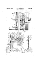
- Figure 1 is adiminutive front elevation of a power shears equipped with my improved nonrepeating clutch.
- Figure 2 is a fragmentary vertical, transverse section through the power shears taken on line 2 2, Figs. l. and 4,' showing the various parts in their normal Vor inoperative position.
- 1 Y 'y Figure 3 is a fragmentary, vertical, transverse, section through a portion of the clutch Ymechanism* in the position which said parts occupy in Figure 2.
- a Figure 4 is a fragmentary front elevation of the power shears showing the clutch parts in the same position as Figure 2. 5
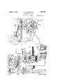
- Figure 5 is a fragmentary, vertical, transverse section through the power shears similar to Figure'2 but with the clutch engaged gy reason of manual pressure on thetreadle ar. f
- Figure 6 is a fragmentary, vertical, transverse section through. a portion of the clutch mechanism similar to Figure 3 but in the position which said parts occupy in Figure 5;
- Figure 7 is a fragmentary, Vertical, transverse section through the power shears similar to Figures 2 and 5 but with the automatic 4clutch moved to its uncoupled position, this taking place even though the manual pressure upon the treadle is still being applied.
- Figure 8Y is afragmentary-horizontalsection through the power shears taken on .line
- FigureV 9 is afragmentary oblique section rthrough the vcoupling of they clutch taken on .linec9.-v9 of Figure 7.,4 Y
- Figure- 1 0 is a fragmentary horizontal section throughv vsaid :coupling taken on line 10-110 of Figure?.
- Figure 11 is a diminutive, fragmentary,
- FIG. 1 is a detailed, vertical, transverse section through certain of the partsjshown in- Figure 11.
- My invention may be embodied in various forms and in non-repeating, clutches of different constructions, andthe present applications are therefore to be regarded merely as some of the possible organizations which come vwithin the scope of my invention and satisfactorily carry out the function .ofsame in practica
- the same isjconstructed ashfollows as applied ,to a power Y shears v ating mechanism A ofthe machine throughaf pair of eccentrics 13, connecting rods 11h-ete.k -Orbylany other suitablemechanism which performs the desired results, the particular organization of said mechanism depending onfthe nature of'thefwork produced by the machine.
- a horizontal, longitudinal, rock shaft 16 is pivotally mounted at its opposite ends in the lower parts ofthe frame end supports 10 and 11 and has secured thereto, adj acent'the inner faces of said end supports, a pair of treadle arms 17-17 which extend transversely forward and approximately horizontally from said rock shaft 16 and have secured to their outermost ends'a. suitable, horizontal, longitudinal treadle bar'lS.
- This treadle bar is adapted to receive the manual downward pressure of the operators foot as indicated by dotted lines in Figs. 5 and 7. Upward movement of said treadle bar is limited by a suitable pair of stops 19 which arelmounted on the inner faces of the frame end supportsV 10 and 11 and adj ustably engage with the upper Vfaces of their companion treadle arms 17-17.
- Said treadle arms are resiliently urged toward their uppermost positions by a suitable pair of tension springs 29 Whose upper ends are connected tothe frame end supports 10 and'll.
- rock arm 21 Secured by a key 2O or otherwise t0 the outboard end of said rock shaft 16 is a rock arm 21 which extends laterally and forwardly and approximately horizontally from said rock shaft, adjacent the outer face of the one frame end support 11.
- the latter is provided, intermediately of its length, with a forwardly-opening, horizontal, lateral'notch 24, which is adapted to receive the projecting cylindrical end or flying pivot 25 of a trunnion 26, the latter being permanently and pivotally connected with the front, bifurcated arm of an engaging lever 27.
- Said engaging lever is fulcrumed at 28 on the frame ofthe machine (ie, on
- Said trunnion 26 is bored out to slidably receive the intermediate portion of a swinging rod 33 whose upper end is pivotally connected at 34 to the front, bifurcated arm of a throw-out lever 35.
- Said pivot 34 extends outwardly some distance beyond said throwout lever 35 and is slidably and rotatably received within a relatively long slot 36 formed longitudinally in the upper end' of the draw bar 23.
- Saidthrow-out lever 35 is fulcrumed at 28 upon the frame end support 11, this being the same fulcrum which carries the engaging lever 27.
- the lowermost end of the swinging rod 33 is provided with an adjusting nut and washer 37 and also a lock nut 38.
- a helical compression spring 4() ⁇ receives within its bore the lower end of said swinging rod 33, the upper end ofsaid spring bearing against the lower face of aforesaid-trunnion 26 (see Fig. 6), while the lower end of said spring bears against the upper face of said adjustment nut and washer 37.
- Upward movement of said trunnion 26 relatively to the swinging rod 33 (upon which said trunnion slides) is limited by a stop shoulder 41, the function of -wliicliwvill hereinafter be described.
- a cylindrical coupling head or clutch collar 43 Secured by a key 42 or otherwise (see Fig. 9) tosaid outboard end of said main shaft 12v inteimediately ofthe outer face of the frame end support 11 and the inner end of the hub of the pulley drive vwheel 15is a cylindrical coupling head or clutch collar 43, in the outer face of which-is formed a square faced, radially-extending retaining groove 44.
- Slidably arranged in ⁇ saidV retaining groove 44 is the rectangular head 45 of a clutch dog 46 whose inner end is cylindrically .formed andis slidably received wit-hin a cylindrical socket 47 which is bored longitudinally into the outer face of said. clutch col- ⁇ lar 43.
- Said clutch dog 46 is resiliently urged longitudinally outwardly by a suitable compression spring 48, whose inner end abuts againstthetrans.- verse bottom wall of said cylindrical socket 47, while its ⁇ outer end (see also Fig. 8) abuts against the transverse bottoinwall of a cylindrical pocket 50 whichis formed coaxially Vin said ⁇ clutch dog 46 and extends longitudinally outwardly from the inner ⁇ transverse face thereof.
- a radial clutch keyway 51 having its advancing or leading corner bevelled at 52 to facilitate the longitudinal entrance therein of the clutch dog-46.4
- the latter Y also is provided with a bevelled end face 53 which bevel additionally aids in .facilitating engagement between said clutchdog 46 and the pulley- Wheel clutch keyway 51.
- This bevel 53 of said clutch dog 46 has another function which will hereinafter be described.
- the term coupling will hereinafter be used to designate those parts which directly couple said pulley wheel 15 to said main shaft12, in contra-distinction to the other cooperating members which only control VVsaid coupling e f
- the outer portion oftheouter face of said clutch dog 46 is suitably bevelled at,53as hereinbeforedescribed.V Thiscons truction enables the' same to make a broadfaced contact with the bevelled face 32 of the hardened engaging blade 31 ofthe engaging ⁇ lever 27.
- This outerbevelled end of saidhardened engaging blade 31 is adapted to be resiliently moved down adjacent ⁇ the outer orend face of the clutch collar 43 and to be received within a suitable, annular', ,coaxial rabbet 55 which is 'formed in the outer, rear corner of the hub of the pulley "wheel 15 (see Figs. 2, 7', 8,'9 and 10).l hen said engagement vblade Vis in this position (down, as in Figs. 2, 3, 9 and 10) any counter clockwise rotation of the main shaft 12 (etogether. with its clutch collar 43, clutch dog 46, etc.) will cause the inclined face 53 of said clutch dog 46 to come into Contact with said bevelled face 32 of said engaging blade 31.
- cam'segment 62 Secured' by vscrews 61 or otherwise to the clutch collar 43 is a cam'segment 62 (see Figs. v9, 7, 8, 5 and 2). This cam'segment is adapted'tov depress the rear end of the throw-out lever 35 in a manner whichcan best be understood by an analysis of themechanism as a whole.
- the swinging rod 33 itself is located in position byy being directly pivoted at 34to the forward arm of the throw-out lever 35, which latter is, in turn, located in limiting position by a suitable stop pin 63 secured to the frame ⁇ end support 11;
- a suitable stop pin 63 secured to the frame ⁇ end support 11;
- the throw-out lever 35 is shown as having been turned in a clockwise direction by the momentary position of the cam segment 62.
- this cam segment moves past the lower end of this lever 35 said lever is not able to change its position because the just mentioned actuation of said cam segment 62 has permitted the engaging lever 27 to move to its eXtreme clockwise position, in which position its pivot prevents the upper end of the draw bar 23 from m'oving forwardly and hence prevents a forward move ment of the pin 34 of the throw-out lever 35 and consequently also prevents any counterclockwise rotation of said throw-out lever 35.
- said throw-out lever maintains the position of Fig. 7 even after the cam segment 62 has passed by its tail end.
- FIG. 11 and 12 A modified form of the invention is illustrated in Figs. 11 and 12.
- the geometrical relationship and functioning of the parts is very similar to that of the construction of Figs. 1-10 inclusive except that the coupling of the parts is effected by an upward instead of a downward movement of a draw bar 231.
- the engaging lever 271 and the throw-out lever 351 are both pivoted upon' a common fulcrum 281, and said engaging lever is provided with a hard- Vened steel engaging blade 311 which is provided with a bevelled end 321 and is adapted to actuate the clutch dog 461.
- the latter is adapted to couple the pulley wheel 151 with the main drive shaft 121 whenever aforesaid draw bar 231 is moved upwardly, and to uncouple said pulley wheel and drive shaft Whenever said draw bar is manually retained in its elevated position, or is manually moved to its lowermost position very shortly after the coupling has been effected and before the main drive shaft 121 has rotated more than the major part of one single revolution.
- Said draw bar 231 is provided with a slot 331 in whichis slidably received a sliding pivot 341, the latter being arranged at the outer end of the throw-out lever 351.
- a sliding pivot 341 Piv otally arranged (adjacent said pivot 341) at the outer end of said throw-out lever is a trunnion A261 (see Fig. 12) through which slides a swinging rod 331 carrying a coinpression spring 401 rat its lower end.
- the upper end of said swinging rod is pivoted at 251 directly to the outer end of the engaging lever 271.
- This pivot 251 normally rests in a lateral notch 241 so that when said draw bar 231 is moved upwardly, the outer - ⁇ end of said-engaging lever 271 is also raised and the clutchdog 461allowed to spring out and couple' the pulley wheel151 and-main shaftl 121. If, however; said draw bar 231 be Vretainedinits ,manually elevated'position, a cam segment'621 arrives at a point inits rotationwhe're it is enabled to upwardly and outwardly move the inner end of the throwont lever 351.
- This partial, clockwise rotation of said throw-out lever causes its sliding pivot 341 to move inwardly and to move the lateral notch 241- out of engagement with the flying pivot 251 and thus permitting the engaging leverI 271 to be moved in a clocks wise direction.
- the force which is necessary for this clockwise partial rotation of said engaging lever 271 is obtained as a result of the downward movement of the trimnion 261 which compresses the spring 401 and hence pushes down against the lower end of the swinging rod 331,*which latter in turn f depresses its flying pivot 251 and thereby ele- Y vates the inner end of the engaging lever 271.
- a throw-out lever having one of its arms slid-l ably pivoted in said slot and actuated by said main shaft; an engaging lever connectedwith said draw bar and resiliently connected with f the sliding pivot of said throw-out lever;
- a nonrepeating clutch associated with a machine having a frame, a main shaft, a power drive and a coupling adapted to connect said power shaft and power drive and f'comprising a longitudinally and manually movable draw bar having a transverse notch and a slot; an engaging lever arranged to control said coupling and having a iying pivot normally received within said lateral notch; a trunnion head pivoted4 to said engagement lever; a swinging rod slidably connected with said trunnion head; a spring interposed between said swinging rod and said engaging lever; and a throw-out lever actuated by said main shaft and provided with a slidingpivot which slides within said sloty of saiddraw barandjalso pivotally connects said throw-out lever with said swinging rod.
- Anonrepeating clutchassociated with a mach-ine having a frame, a mainshaft, a power driveA and a coupling adapted to connect said powerY 'shaft 'and power driveA and comprising a longitudinally and manuallyV movable drawbar having a transverse notch and a slot; an engaging lever arranged to control said coupling and having a 'lyingf pivot normallyreceived within sai'dlateral notch; a trunnion head pivoted to said en-v gagement lever; a swinging rod slidably connected with saidrtrunnio'n head; and having a stop shoulder which -bears againstsaid trunnion head and therebylocates said en#- gaging lever in position to provide operatingclearance when the various parts are in theirV normal position.I I g el.
- a nonrepeating clutch associatedwith* a machine having a frame, a mainshaft, la power drive and a coupling adapted to connect said powerV shaft and power drive andr comprising a: longitudinally ⁇ and Ymanually movable. draw bar having a transverse notchand a slot; an engaginglever arrangedto control said coupling and having a flyingpivot normally received 'within said'V lateral notch;v a trunnion head pivoted vtosaid lengagement lever; a swinging rod slidably connected with said trunnion'head; a spring interposedbetween said vswinging rod and saidA engaging lever;a throw-out lever fulcrumed on the same fulcrum as that of-'said engaging lever; a sliding pivot which slides within said slot of said draw bar and'pivotally con-v nects said throw-out lever with said swinging 5.1A nonrepeating clutch associated withl a machine having a frame,
- movable draw bar having a transverse notch g1 an engagement lever arranged to control said coupling and fulcrumed on said'frame and having a flying pivot which is adapted tobe received within said transverse notch; a throw-out lever actuated by said main shaft and alsoY fulcrumed on said frame and adapt.A ed to vmovexsaid draw bar laterally to disengage the same from said engaginglever; a; swinging rod pivoted to said engaging lever and an adjustable spring interposed between said swinging rod andsaid engaging lever.
- a nonrepeating clutch associated with al machine having a frame, a main shaft, a
- a nonrepeating clutch associated with a machine having a frame, a main shaft, a power drive and a coupling adapted to connect said power shaft and power driveand comprising a draw vbar adapted to be moved manually and longitudinally a swinging rod at the central part of, said swinging," ⁇ rod and having its ends adapted to be received within said lateral notch of said draw bar; and a resilient connection between said trunnion head and said swinging rod.
- an engaging lever arranged to control said Y coupling and slidably connected with said swinging rod and detachably and pivotally connected with said draw bar; and a throwout lever actuated by said main shaft and pivoted to said swinging rod and slidably and pivotally connected with said draw bar.
- a nonrepeating clutch associated with a machine having a frame, ⁇ a main shaft, a power drive and a coupling adapted to conneet said power shaft and power drive and comprising a manually and longitudinally f movable draw, bar having a slot at its upper end and a lateral notch below said slot; an engagement lever fulcrumed o-n said frame and arranged to, control said coupling; a throwout lever also fulcrumed on said frame and actuated by said main shaft; a swinging rod having a sliding pivot at its upper end which pivotally connectssaid rod with said throw out lever and is slidably received within said slot of said draw bar; a trunnion head -slidably arranged at the central part of.
- said swinging rod and having its ends adapted to be received within said lateral notch of said draw bar; an adjustment nut arranged at the lower end of said swinging rod; and a1 compression spring arranged on said rod between the adjustment nut thereof and the lower face of said trunnion head.
- a nonrepeati'ng clutch associated with a machine having a frame, a main shaft, a power drive and a coupling adapted to connect said power shaft and power drive and comprising: a manually rotatable rock shaft; a rock arm secured thereto; an upright draw bar pivoted at its lower end to said rock arm and having a slot at its upper end and a lateral notch below said slot; an engagement lever fulcrumed on said frame and arranged to control said coupling; a throw-out lever fulcrunied on the same fulcrum as that of vsaid engagement lever and actuated by said
Landscapes
- Engineering & Computer Science (AREA)
- General Engineering & Computer Science (AREA)
- Mechanical Engineering (AREA)
- Mechanical Operated Clutches (AREA)
Description
.P. R HAHNEMANN NONREPEATI NG CLUTCH Filed Dec. `29, 1930 3 Sheecs-SheefI April r12, 1932.
April l2, 1932. P. R. HAHNEMANN NONREPEATING' CLUTCH Filed Dc.
29, 1930 3 Sheets-Sheet April l2, 1932.
P. R HAHNEMANN NONREPEATING CLUTCH Filed Dec. 29, 1930 3 Sheets-Sheet 3 Patented Apr. 12, 1932 lUNITED' sTATs PAUL R. HAHNEMANN, or BUFFALO, NEWYORK, ASSIGNOR'TO NIAGArtAivrAoz-IINE sa TOOL WORKS, or BUFFALO, NEW YORK', A CORPORATION or NEW YORK- NONREPEATING CLUTCH" Application filed December 29,1930. Serial No. 505,234. p
.as a shears ory punch press, and more particularly relates to that type of rclutch in which 'the main shaft of the machine is rotated once and only once foreachmanual actuating of said clutch, irrespective of the length of time said manual pressure is being exerted. A Y j The principal object of the invention is to provide a reliable and sturdy clutch o f'this nonrepeating character in which a minimum amount of machine work upon the main frame is required and which is otherwisewso constructed as to be lowin manufacturing cost.` Numerous other collateral obJects of the invention and practical solutions thereofV are disclosed in detail in the herein patent specification wherein: Y
Inthe accompanying drawings Figure 1 is adiminutive front elevation of a power shears equipped with my improved nonrepeating clutch.
Figure 2 is a fragmentary vertical, transverse section through the power shears taken on line 2 2, Figs. l. and 4,' showing the various parts in their normal Vor inoperative position. 1 Y 'y Figure 3 is a fragmentary, vertical, transverse, section through a portion of the clutch Ymechanism* in the position which said parts occupy in Figure 2.
AFigure 4 is a fragmentary front elevation of the power shears showing the clutch parts in the same position as Figure 2. 5
Figure 5 is a fragmentary, vertical, transverse section through the power shears similar to Figure'2 but with the clutch engaged gy reason of manual pressure on thetreadle ar. f
Figure 6 is a fragmentary, vertical, transverse section through. a portion of the clutch mechanism similar to Figure 3 but in the position which said parts occupy in Figure 5;
Figure 7 is a fragmentary, Vertical, transverse section through the power shears similar to Figures 2 and 5 but with the automatic 4clutch moved to its uncoupled position, this taking place even though the manual pressure upon the treadle is still being applied.
Figure 8Y is afragmentary-horizontalsection through the power shears taken on .line
8i-8 of Figure 2. I
FigureV 9is afragmentary oblique section rthrough the vcoupling of they clutch taken on .linec9.-v9 ofFigure 7.,4 Y
. Figure- 1 0 isa fragmentary horizontal section throughv vsaid :coupling taken on line 10-110 of Figure?. Figure 11 is a diminutive, fragmentary,
vertical, transverse section through a power drive machine, showing a modified overhead form of the invention. 1 Figure l2 is a detailed, vertical, transverse section through certain of the partsjshown in-Figure 11.
In the following description, similar characters oflreference indicate like parts 1 in the several figures of the drawings. .p Y
My invention may be embodied in various forms and in non-repeating, clutches of different constructions, andthe present applications are therefore to be regarded merely as some of the possible organizations which come vwithin the scope of my invention and satisfactorily carry out the function .ofsame in practica As here shown (referring for the Vpresent to Figs. l-'l' 0) the same isjconstructed ashfollows as applied ,to a power Y shears v ating mechanism A ofthe machine throughaf pair of eccentrics 13, connecting rods 11h-ete.k -Orbylany other suitablemechanism which performs the desired results, the particular organization of said mechanism depending onfthe nature of'thefwork produced by the machine. This matter hasno pertinency to the present invention except that the usefulness of this inventionis confined to that type Vof machinery y( shears, punch press and the like) in whichitvis desirable that a Asingle manual manipulation ofthe machine cause one and only'one rotation of the mainshaft 12. Journaled upon the outboard end ofsaid main shaft 12 is a pulley drive wheel 15 which is belt driven from a line shaft or is otherwise arranged to derive power from an external source of power in any one of the usual and well known manners.
It is the function in general of the present invention to couple and unc'ouple this pulley wheel 15 with said main shaft 12.
A horizontal, longitudinal, rock shaft 16 is pivotally mounted at its opposite ends in the lower parts ofthe frame end supports 10 and 11 and has secured thereto, adj acent'the inner faces of said end supports, a pair of treadle arms 17-17 which extend transversely forward and approximately horizontally from said rock shaft 16 and have secured to their outermost ends'a. suitable, horizontal, longitudinal treadle bar'lS. This treadle bar is adapted to receive the manual downward pressure of the operators foot as indicated by dotted lines in Figs. 5 and 7. Upward movement of said treadle bar is limited by a suitable pair of stops 19 which arelmounted on the inner faces of the frame end supportsV 10 and 11 and adj ustably engage with the upper Vfaces of their companion treadle arms 17-17. Said treadle arms are resiliently urged toward their uppermost positions by a suitable pair of tension springs 29 Whose upper ends are connected tothe frame end supports 10 and'll.
Secured by a key 2O or otherwise t0 the outboard end of said rock shaft 16 is a rock arm 21 which extends laterally and forwardly and approximately horizontally from said rock shaft, adjacent the outer face of the one frame end support 11. Pivoted to the outer end'of said rock arm 21 at 22 is an upstanding or approximately perpendicular draw bar 23. The latter is provided, intermediately of its length, with a forwardly-opening, horizontal, lateral'notch 24, which is adapted to receive the projecting cylindrical end or flying pivot 25 of a trunnion 26, the latter being permanently and pivotally connected with the front, bifurcated arm of an engaging lever 27. Said engaging lever is fulcrumed at 28 on the frame ofthe machine (ie, on
the frame end supportV 11) and has secured thereto by cap screws 30 or otherwise a hardened steel engaging blade 31 whose inner, rear face is suitably bevelled at 32, as best shown in Fig. 8. Y
Said trunnion 26 is bored out to slidably receive the intermediate portion of a swinging rod 33 whose upper end is pivotally connected at 34 to the front, bifurcated arm of a throw-out lever 35. Said pivot 34 extends outwardly some distance beyond said throwout lever 35 and is slidably and rotatably received within a relatively long slot 36 formed longitudinally in the upper end' of the draw bar 23. Saidthrow-out lever 35 is fulcrumed at 28 upon the frame end support 11, this being the same fulcrum which carries the engaging lever 27.
The lowermost end of the swinging rod 33 is provided with an adjusting nut and washer 37 and also a lock nut 38. A helical compression spring 4()` receives within its bore the lower end of said swinging rod 33, the upper end ofsaid spring bearing against the lower face of aforesaid-trunnion 26 (see Fig. 6), while the lower end of said spring bears against the upper face of said adjustment nut and washer 37. Upward movement of said trunnion 26 relatively to the swinging rod 33 (upon which said trunnion slides) is limited by a stop shoulder 41, the function of -wliicliwvill hereinafter be described.
Secured by a key 42 or otherwise (see Fig. 9) tosaid outboard end of said main shaft 12v inteimediately ofthe outer face of the frame end support 11 and the inner end of the hub of the pulley drive vwheel 15is a cylindrical coupling head or clutch collar 43, in the outer face of which-is formed a square faced, radially-extending retaining groove 44. Slidably arranged in` saidV retaining groove 44 is the rectangular head 45 of a clutch dog 46 whose inner end is cylindrically .formed andis slidably received wit-hin a cylindrical socket 47 which is bored longitudinally into the outer face of said. clutch col- `lar 43. The axis of said cylindrical socket 47 Vis parallel to but is eccentric with respect to the axis of the main shaft 12.v Said clutch dog 46 is resiliently urged longitudinally outwardly by a suitable compression spring 48, whose inner end abuts againstthetrans.- verse bottom wall of said cylindrical socket 47, while its `outer end (see also Fig. 8) abuts against the transverse bottoinwall of a cylindrical pocket 50 whichis formed coaxially Vin said `clutch dog 46 and extends longitudinally outwardly from the inner` transverse face thereof. lt will be noted that the generousproportions and shape of the rectangular head 45 of said clutch dog 46 enables a heavy and suddenly applied load to he transmitted tangentially (without deformation of any of theV parts) from saidr clutch dog 46 to the clutch collar 43 in, which latter said clutch dog vlongitudinally slides.
, Formed in the inner face of the hub ofthe pulley wheel 15 (asbest shown in Fig. 10) is a radial clutch keyway 51having its advancing or leading corner bevelled at 52 to facilitate the longitudinal entrance therein of the clutch dog-46.4 The latter Yalso is provided with a bevelled end face 53 which bevel additionally aids in .facilitating engagement between said clutchdog 46 and the pulley- Wheel clutch keyway 51. This bevel 53 of said clutch dog 46 has another function which will hereinafter be described.
7 `When the pulley wheel 15 is rotatingina counterclockwise direction (viewed from the position of Figs. 2, 5, 6 and 7 its radial clutch keyway 51 arrives at a position in which said keywayis in register with the vrec- Y' se tangular head of said clutch dog 46 whereupon thelatteris thrust longitudinally out-A `43,'the result is that said pulley wheel 15 is coupled to the main shaft 12, and hence to the entire working mechanism A of the machine. To differentiate between thedifierent functions of the parts constituting the present invention, the term coupling will hereinafter be used to designate those parts which directly couple said pulley wheel 15 to said main shaft12, in contra-distinction to the other cooperating members which only control VVsaid coupling e f As best shown in Figs. 7, 8 and 9, the outer portion oftheouter face of said clutch dog 46 is suitably bevelled at,53as hereinbeforedescribed.V Thiscons truction enables the' same to make a broadfaced contact with the bevelled face 32 of the hardened engaging blade 31 ofthe engaging `lever 27. This outerbevelled end of saidhardened engaging blade 31 .is adapted to be resiliently moved down adjacent` the outer orend face of the clutch collar 43 and to be received within a suitable, annular', ,coaxial rabbet 55 which is 'formed in the outer, rear corner of the hub of the pulley "wheel 15 (see Figs. 2, 7', 8,'9 and 10).l hen said engagement vblade Vis in this position (down, as in Figs. 2, 3, 9 and 10) any counter clockwise rotation of the main shaft 12 (etogether. with its clutch collar 43, clutch dog 46, etc.) will cause the inclined face 53 of said clutch dog 46 to come into Contact with said bevelled face 32 of said engaging blade 31. This action causes said.v clutchv dog to be pushed longitudinally inwardlynagainst the resistance of the clutch dog compression spring 48, and to move the rectangular head 45 of saidl clutch dog out of the radial keywayv 51 ofthe pulley wheel 15. vThis disengavges the coupling7 between said pulley wheel 15 and the main shaft 12 and thereby uncouples the drive to the operatingmechanism A. i,
'When the power being delivered to said main shaft 12 has just been uncoupled it is Vobvious that a' certain amount of momentum will still remain in the lmain shaft and the parts which have been moving therewith. lf this momentum is sufficient, the clutch dog 46 might be able to coast clear past the engaging blade 31. To cut down this momentum suiciently, so that such an excessive coasting may not occur, a prony brake 56 is loosely pivoted to the machine frame at 57, while its other end is split and is provided with a pair of draw-up ears 58 which areadapted to be adjustably drawn together a suitable l draw-up screw 60. This adjustment need not be at all accurate inasmuch as the clutch dog 46 must coast a considerable distance along the engaging blade 31 `before it can yagain fly out and couple the pulley wheel 15 to the main shaft 12. i,
Secured' by vscrews 61 or otherwise to the clutch collar 43 is a cam'segment 62 (see Figs. v9, 7, 8, 5 and 2). This cam'segment is adapted'tov depress the rear end of the throw-out lever 35 in a manner whichcan best be understood by an analysis of themechanism as a whole. Y
' Operation Thennormal position of the parts of the vhereinfclutch is to. be taken to indicate that position in which the pulley wheel 15 isrotatingat' a constant speed but is uncoupled from the main shaft 12 and hence from the operating. mechanism Av of the power shears or other machine which is equipped with the herein invention. Y This position (in which no power is being delivered to the main shaft 12)- is illustrated in Figs, 1-4, and in this position the engagement blade 31 of the engagement lever 27is in its'lowered position and is vpushing the clutch dog 46 inwardly out of engagement withthe radial keyway 51 of the pulley wheel 15. In this position, clearance between the lower face of said engaging blade 31 and the periphery of the rabbet 55 is prokvided-by the stop shoulder 41 Vof the swinging rod 33 against whichshoulder the trunnion 26 is u rged by -the compression spring 40. The swinging rod 33 itself is located in position byy being directly pivoted at 34to the forward arm of the throw-out lever 35, which latter is, in turn, located in limiting position by a suitable stop pin 63 secured to the frame` end support 11; Hence, as the trunnion 26 is itself located bythe throwout lever 35 and is pivoted directly to they frontarm of the engaging lever 27,` suchJa ydefinite positioning of said trunnion definitely positions said engagement lever and kprovides the proper clearance between its engagement blade 31 and the hub of Vthe pulleywheel 15. In this-normal position, the drawV bar 23 is definitely located in; position by means of the two tension springs 29 which resilienttheir adjustable stops 19. Suitable clearance between the throw-out lever 35 and the periphery of the clutch collarV 43 is provided `24 of 'said draw bar 23.` As this flying pivot 25passes through the bifurcated forward arm' of the engaging lever 27, it follows that the said depressing of said flying pivot elevatesthe engaging blade 31and allows the coupling to be engaged so that power flows 'I" fic ILO
from the constantly turning pulley wheel 15 to the main shaft 12. In this position of Fig. it will be noticed that the position of the throw-out lever 35 has not been affected by the movementof the'treadle bar 18 from the position of Fig. 2 to the position of Fig. 5. This is so because the sliding pivot 34 of said throw-out lever is received within the slot 36 of the draw bar 23 and hence the merely vertical movement of said draw bar 23 has no effect on said throw-outlever 35.
In a power shears, punch press or other machine of the same general character, it is desirable that the main shaft rotate once and only once for every separate depression of the treadle bar 18. To accomplish this desired result, it is necessary to disengage the coupling even though said treadle 18 continues to be depressed as in Fig. 7. In this figure it will be seen that the cam segment 62 (secured to clutch collar 43) has moved around under the rear arm of throw-out lever 35 and has partially rotated the latter in a clockwise direction about its fulcrum 28. This partial rotation of said throw-out lever 35 causes its sliding pivot 34 to be moved somewhat to the rear (to the right in Fig. 7) which also throws the upper end of the draw bar 23 in the same direction. This movement moves the lateral notch 24 of said draw bar 23 out of engagement with the flying pivot 25. At the same time the upward component of the movement of the sliding pivot 34 causes the swing rod 33 to be also moved upwardly, thereby pushing up the lower end of the compression spring- 40. The upper end of said spring, in turn, pushes up the trunnion 26 carrying the flying pivot 25 and hence causes the front arm of the engaging lever 27 to be elevated. rThis causes the clutch dog 46 to be pushed inwardly so as to'uncouple the pulley wheel from the main shaft 12. This uncoupled condition continues as long as the operator continues to depress the trea dle bar 18 as illustrated in Fig. 7 In this Fig. 7 the throw-out lever 35 is shown as having been turned in a clockwise direction by the momentary position of the cam segment 62. When this cam segment, however, moves past the lower end of this lever 35 said lever is not able to change its position because the just mentioned actuation of said cam segment 62 has permitted the engaging lever 27 to move to its eXtreme clockwise position, in which position its pivot prevents the upper end of the draw bar 23 from m'oving forwardly and hence prevents a forward move ment of the pin 34 of the throw-out lever 35 and consequently also prevents any counterclockwise rotation of said throw-out lever 35. By this means said throw-out lever maintains the position of Fig. 7 even after the cam segment 62 has passed by its tail end.
If the operator now releases his foot pressure upon the treadle bar 18 then the treadle springs 29 pull up the draw bar 23. Inasmuch as the upper part of said draw bar is at this time being urged outwardly (to the left in Fig. 7) bythe pressure of spring 40 and against the flying pivot 25, it follows that as said draw bar 23 moves upwardly relatively to said flying pivot 25, the latter follows along the beveled portion of the notch 24 until it finally arrives opposite the semi-circular part or bottoml of said notch, whereupon the flying pivot 25 is nolonger able to prevent outward movement of the upper end of the draw bar 23 and hence the spring 40 urges the pivot 34vtoward the flying pivot 25 and thereby causes said pivot 34 to swing down and outwardly about its axis of rotation 28. This causes the upper end of the draw bar 23 to move outwardly until the flying pivot 25 is snugly lodged in the notch 24 and the throwout lever 35 is limited in its further counterclockwise rotation (as seen in Fig. 7) by the stop G3. This brings all of the parts of the clutch back to the position thereof shown in Fig. 2, which represents the beginning of the cycle of operations, in which case the treadle bar 18 is again in position to again be depressed by the operator so as to again couple the flywheel 15 to the main shaft 12.
A modified form of the invention is illustrated in Figs. 11 and 12. In this case the geometrical relationship and functioning of the parts is very similar to that of the construction of Figs. 1-10 inclusive except that the coupling of the parts is effected by an upward instead of a downward movement of a draw bar 231. In this case the engaging lever 271 and the throw-out lever 351 are both pivoted upon' a common fulcrum 281, and said engaging lever is provided with a hard- Vened steel engaging blade 311 which is provided with a bevelled end 321 and is adapted to actuate the clutch dog 461. The latter is adapted to couple the pulley wheel 151 with the main drive shaft 121 whenever aforesaid draw bar 231 is moved upwardly, and to uncouple said pulley wheel and drive shaft Whenever said draw bar is manually retained in its elevated position, or is manually moved to its lowermost position very shortly after the coupling has been effected and before the main drive shaft 121 has rotated more than the major part of one single revolution.
Said draw bar 231 is provided with a slot 331 in whichis slidably received a sliding pivot 341, the latter being arranged at the outer end of the throw-out lever 351. Piv otally arranged (adjacent said pivot 341) at the outer end of said throw-out lever is a trunnion A261 (see Fig. 12) through which slides a swinging rod 331 carrying a coinpression spring 401 rat its lower end. The upper end of said swinging rod is pivoted at 251 directly to the outer end of the engaging lever 271. This pivot 251 normally rests in a lateral notch 241 so that when said draw bar 231 is moved upwardly, the outer -`end of said-engaging lever 271 is also raised and the clutchdog 461allowed to spring out and couple' the pulley wheel151 and-main shaftl 121. If, however; said draw bar 231 be Vretainedinits ,manually elevated'position, a cam segment'621 arrives at a point inits rotationwhe're it is enabled to upwardly and outwardly move the inner end of the throwont lever 351. This partial, clockwise rotation of said throw-out lever causes its sliding pivot 341 to move inwardly and to move the lateral notch 241- out of engagement with the flying pivot 251 and thus permitting the engaging leverI 271 to be moved in a clocks wise direction. The force which is necessary for this clockwise partial rotation of said engaging lever 271 is obtained as a result of the downward movement of the trimnion 261 which compresses the spring 401 and hence pushes down against the lower end of the swinging rod 331,*which latter in turn f depresses its flying pivot 251 and thereby ele- Y vates the inner end of the engaging lever 271.
' comprising a longitudinally and manually movable draw bar having a longitudinal slot;
a throw-out lever having one of its arms slid-l ably pivoted in said slot and actuated by said main shaft; an engaging lever connectedwith said draw bar and resiliently connected with f the sliding pivot of said throw-out lever; and
means for disconnecting said draw bar from said engaging lever and permitting the resilient connection between said throw-out lever and engaging lever to move the latter to its clutch disengaging position.
2. A nonrepeating clutch associated with a machine having a frame, a main shaft, a power drive and a coupling adapted to connect said power shaft and power drive and f'comprising a longitudinally and manually movable draw bar having a transverse notch and a slot; an engaging lever arranged to control said coupling and having a iying pivot normally received within said lateral notch; a trunnion head pivoted4 to said engagement lever; a swinging rod slidably connected with said trunnion head; a spring interposed between said swinging rod and said engaging lever; and a throw-out lever actuated by said main shaft and provided with a slidingpivot which slides within said sloty of saiddraw barandjalso pivotally connects said throw-out lever with said swinging rod. 3. Anonrepeating clutchassociated with a mach-ine having a frame, a mainshaft, a power driveA and a coupling adapted to connect said powerY 'shaft 'and power driveA and comprising a longitudinally and manuallyV movable drawbar having a transverse notch and a slot; an engaging lever arranged to control said coupling and having a 'lyingf pivot normallyreceived within sai'dlateral notch; a trunnion head pivoted to said en-v gagement lever; a swinging rod slidably connected with saidrtrunnio'n head; and having a stop shoulder which -bears againstsaid trunnion head and therebylocates said en#- gaging lever in position to provide operatingclearance when the various parts are in theirV normal position.I I g el. A nonrepeating clutch associatedwith* a machine having a frame, a mainshaft, la power drive and a coupling adapted to connect said powerV shaft and power drive andr comprising a: longitudinally `and Ymanually movable. draw bar having a transverse notchand a slot; an engaginglever arrangedto control said coupling and having a flyingpivot normally received 'within said'V lateral notch;v a trunnion head pivoted vtosaid lengagement lever; a swinging rod slidably connected with said trunnion'head; a spring interposedbetween said vswinging rod and saidA engaging lever;a throw-out lever fulcrumed on the same fulcrum as that of-'said engaging lever; a sliding pivot which slides within said slot of said draw bar and'pivotally con-v nects said throw-out lever with said swinging 5.1A nonrepeating clutch associated withl a machine having a frame, a main shaft,a` power drive and a coupling adapted to con nectsaid .power-shaftand power drive andl comprising a longitudinally and manually? movable draw bar having a transverse notch g1 an engagement lever arranged to control said coupling and fulcrumed on said'frame and having a flying pivot which is adapted tobe received within said transverse notch; a throw-out lever actuated by said main shaft and alsoY fulcrumed on said frame and adapt.A ed to vmovexsaid draw bar laterally to disengage the same from said engaginglever; a; swinging rod pivoted to said engaging lever and an adjustable spring interposed between said swinging rod andsaid engaging lever.'
6. A nonrepeating clutch associated with al machine having a frame, a main shaft, a"
power drive and a coupling' adapted to con nect said power vshaft and power drive and comprising a longitudinally-and manually movable draw bar having av transverse notch:v and a slot; an engagement lever arranged to control said coupling" and4 having ai flyingV l pivot which is adapted to be received within said transverse notch; a throw-out lever' actuated by saidm'ain shaft and having a sliding pivot which is received within said slot and normally bears against one end thereof to Vdefinitely limit the movement of said throw-out lever inthe one direction, said throw-out lever being adapted to laterally movev said draw bar out of engagement with said engaging lever; and a resilient connection between said engaging lever and said throw/out lever.
7. A nonrepeating clutch associated with a machine having a frame, a main shaft, a power drive and a coupling adapted to connect said power shaft and power driveand comprising a draw vbar adapted to be moved manually and longitudinally a swinging rod at the central part of, said swinging,"` rod and having its ends adapted to be received within said lateral notch of said draw bar; and a resilient connection between said trunnion head and said swinging rod.
In testimony whereof I hereby aflix mysignature.
PAUL R. HAHN'EMANN.
an engaging lever arranged to control said Y coupling and slidably connected with said swinging rod and detachably and pivotally connected with said draw bar; and a throwout lever actuated by said main shaft and pivoted to said swinging rod and slidably and pivotally connected with said draw bar.
8. A nonrepeating clutch associated with a machine having a frame, `a main shaft, a power drive and a coupling adapted to conneet said power shaft and power drive and comprising a manually and longitudinally f movable draw, bar having a slot at its upper end and a lateral notch below said slot; an engagement lever fulcrumed o-n said frame and arranged to, control said coupling; a throwout lever also fulcrumed on said frame and actuated by said main shaft; a swinging rod having a sliding pivot at its upper end which pivotally connectssaid rod with said throw out lever and is slidably received within said slot of said draw bar; a trunnion head -slidably arranged at the central part of. said swinging rod and having its ends adapted to be received within said lateral notch of said draw bar; an adjustment nut arranged at the lower end of said swinging rod; and a1 compression spring arranged on said rod between the adjustment nut thereof and the lower face of said trunnion head.
9. A nonrepeati'ng clutch associated with a machine having a frame, a main shaft, a power drive and a coupling adapted to connect said power shaft and power drive and comprising: a manually rotatable rock shaft; a rock arm secured thereto; an upright draw bar pivoted at its lower end to said rock arm and having a slot at its upper end and a lateral notch below said slot; an engagement lever fulcrumed on said frame and arranged to control said coupling; a throw-out lever fulcrunied on the same fulcrum as that of vsaid engagement lever and actuated by said
Priority Applications (1)
| Application Number | Priority Date | Filing Date | Title |
|---|---|---|---|
| US505234A US1853766A (en) | 1930-12-29 | 1930-12-29 | Nonrepeating clutch |
Applications Claiming Priority (1)
| Application Number | Priority Date | Filing Date | Title |
|---|---|---|---|
| US505234A US1853766A (en) | 1930-12-29 | 1930-12-29 | Nonrepeating clutch |
Publications (1)
| Publication Number | Publication Date |
|---|---|
| US1853766A true US1853766A (en) | 1932-04-12 |
Family
ID=24009528
Family Applications (1)
| Application Number | Title | Priority Date | Filing Date |
|---|---|---|---|
| US505234A Expired - Lifetime US1853766A (en) | 1930-12-29 | 1930-12-29 | Nonrepeating clutch |
Country Status (1)
| Country | Link |
|---|---|
| US (1) | US1853766A (en) |
Cited By (3)
| Publication number | Priority date | Publication date | Assignee | Title |
|---|---|---|---|---|
| US2419467A (en) * | 1942-10-26 | 1947-04-22 | Deere & Co | Clutch mechanism |
| US2795307A (en) * | 1952-03-14 | 1957-06-11 | Fred G Burg | Cyclically operable power transmission mechanism |
| US3066565A (en) * | 1953-12-21 | 1962-12-04 | Royal Mcbee Corp | Electric card groover |
-
1930
- 1930-12-29 US US505234A patent/US1853766A/en not_active Expired - Lifetime
Cited By (3)
| Publication number | Priority date | Publication date | Assignee | Title |
|---|---|---|---|---|
| US2419467A (en) * | 1942-10-26 | 1947-04-22 | Deere & Co | Clutch mechanism |
| US2795307A (en) * | 1952-03-14 | 1957-06-11 | Fred G Burg | Cyclically operable power transmission mechanism |
| US3066565A (en) * | 1953-12-21 | 1962-12-04 | Royal Mcbee Corp | Electric card groover |
Similar Documents
| Publication | Publication Date | Title |
|---|---|---|
| US1853766A (en) | Nonrepeating clutch | |
| US2052152A (en) | Torque transmission mechanism | |
| US2006144A (en) | Feed knock-off mechanism for lathes | |
| US2313708A (en) | Overload clutch | |
| US2723406A (en) | Screw-cutting attachment for machine tools having a reversible working spindle | |
| US2269064A (en) | Power feed mechanism for machine tools | |
| US2874816A (en) | Adjustable clutch for metal forming machines | |
| US2568785A (en) | Rocking type of drilling and tapping appliance for automatic lathes | |
| US3181668A (en) | Double clutch and control linkage therefor | |
| US858801A (en) | Clutch mechanism. | |
| US2727610A (en) | Oscillating drive and clutch means for electrically driven fans and the like | |
| US1730429A (en) | Device for boring noncircular holes | |
| US1320375A (en) | Screw-driving machine | |
| US1872132A (en) | Nonrepeat mechanism for power presses | |
| US1661474A (en) | groene | |
| US2528198A (en) | Actuating apparatus for punch presses | |
| US2204421A (en) | Clutch for punch presses | |
| US2127432A (en) | Paper cutting machine | |
| US2522974A (en) | Clutch mechanism | |
| US1727424A (en) | Milling machine | |
| US2339597A (en) | Automatic drill press | |
| US1657098A (en) | Clutch-operating mechanism | |
| US1630882A (en) | Clutch-operating mechanism for power presses | |
| US1506724A (en) | Machine-tool-table reversing mechanism | |
| US2960203A (en) | Spindle arresting and chucking device for automatic multispindle lathes |