US1853762A - Manifolding device - Google Patents
Manifolding device Download PDFInfo
- Publication number
- US1853762A US1853762A US494094A US49409430A US1853762A US 1853762 A US1853762 A US 1853762A US 494094 A US494094 A US 494094A US 49409430 A US49409430 A US 49409430A US 1853762 A US1853762 A US 1853762A
- Authority
- US
- United States
- Prior art keywords
- platen
- lever
- truck
- frame
- movement
- Prior art date
- Legal status (The legal status is an assumption and is not a legal conclusion. Google has not performed a legal analysis and makes no representation as to the accuracy of the status listed.)
- Expired - Lifetime
Links
Images


Classifications
-
- B—PERFORMING OPERATIONS; TRANSPORTING
- B41—PRINTING; LINING MACHINES; TYPEWRITERS; STAMPS
- B41J—TYPEWRITERS; SELECTIVE PRINTING MECHANISMS, i.e. MECHANISMS PRINTING OTHERWISE THAN FROM A FORME; CORRECTION OF TYPOGRAPHICAL ERRORS
- B41J35/00—Other apparatus or arrangements associated with, or incorporated in, ink-ribbon mechanisms
- B41J35/22—Mechanisms permitting the selective use of a plurality of ink ribbons
Definitions
- This invention relates to new and useful improvements in manifolding devices which may be' readily attached to .any standard typewriting machine without changing such machine in anymaterialrespect,and embodies certain improvements over the inventions disclosed in my co-pendin'g application Serial and in the divisional application thereof Serial No. 194,- 135, filed May 25, 1927, and in application Serial No. 359,934 filed May 2, 1929.
- the present invention, and likewise the inventions of the co-pending applications above noted', is designed for the purpose of writing on jcon.
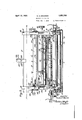
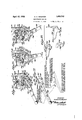
- FIG. 1 is a top plan view of a typewriter carriage embodying my invention
- K Figure 2 is a front elevation thereof
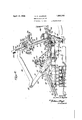
- Figure 3 is a right hand elevation of the carriage
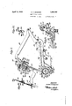
- Figure 4 isa riage
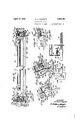
- FIG. 6 is a rear elevation of the collating frame, showing the paper truck thereon, the
- Figure 7 is a vertical sectional viewshowing the collating frame in its normal or rearwardly inclined position, and the platen in its lnormal or forward Yprinting position,
- Figure 8 is a similar view but showing the collating frame in its forward position and the platen 'in ⁇ its rearward position, o
- Figure 9 is a view in elevation of side .bars forming the collating frame,
- Figure 10 is a. fragmentary view in elevation o f one end of a link which supports the .provide ,Aw Tcollating frame and the platen,
- Figure 11 is a horizontal sectional vi'ew taken on the line 11-11 of Figure 2,;
- .'- Figure 12 is an enlarged detailed elevation showing the means for releasing the movf able. clamping bar of the truck and for simultaneouslyreleasing the holding pawls of theI truck from lthe collating frame, i
- Figure 13 is a vertical sectional view show'- in-g a modified form of truck wherein the clamping bar is slidably mounted, the view separate connections for rai ⁇ s ing the tru left hand elevation of the car- ⁇ 5 isa rearelevation 'ofthema'chine' 1 ne ofthe- Y for releasing the truck from the frame,
- Figure 16 is an enlarged detailed side elevation showing the manually operable paper feed roll in its normal or non-feeding'position
- Figure 17 is a vertical sectional view showing more or less diagrammatically a modified .form in which the lower guide roll is disposed fartherto the right of the machine
- Figure 18 is asimilar view but showing the work sheets in a vertical plane and separated from the platen
- Figure 19 is an enlarged detail side elevation showing the spring connection between the table andthe support therefor,
- Figure 20 is an enlarged elevation showing the eonnection between the front of the table and the carriage
- Figure 21 is an enlarged vertical sectional view through the end gage for the work sheets
- Figure 22 is a perspective view of the adjustable pos't with which the carriage return lever cooperates for limiting the line spacing movement of the work sheets to either a single,
- Figure 23 is a view showing the separated parts with which the carriage return lever cooperates for effecting certain movements to the work sheets and carbon strips,
- Figure 24K is a horizontal section showing the carriage return lever in its normal position and with the .various cooperating'elements 4in their normal positions
- Figure 25 is a similar view but showing the carriage return lever moved to a position for Y effecting a single line spacing movement to e the work sheets,
- Figure26 is a view similar to Figure 25 but showing the izarriage return lever moved to a position for effecting a double line spacing movement .to the work sheets,
- Figure 27 is a view of a timing diagram showing the extent of movement of the collaiing frame and the platen, the time of feeding the carbon strips, ⁇ and the time of applying the tension vto said strips,
- Figure 28 is a vertical sectional view f through the carriage and paper guide, illus'- tratin a'modication wherein work sheets of diifrent widths are employed, and
- Figure 29 is an enlarged detail vertical sectional showing of the adjustable upper and lower guides forthe work sheets.
- Theinvention as illustrated in the accompanying drawings is shown as being applied to the well known standard Royal typewriting machine, but it is to be understood that my invention is adapted to be applied to other types of typewriting machines, or to calculating machines and the like.
- the typewriting machine includes a main frame A, a carriage B, a platen G, a mam ribbon D, type bars E which are' operated in the usual manner, and the usual tabular stop rod F.
- the main frame A includes side walls 5 and 6 and a rear wall 7. Fixed to the main frame A is a ybottom railv 8 for supporting the carriage B through the medium of a top rail 9 fixed to the carriage.
- the ca rriage includes end plates 10 and 11 respectively, and rigidly connected to thev front portions of the end plates is a rod 13; Journaled on this rod adjacent the inner faces of the end plates are hanger arms 14, 14;
- the collating frame G includes spaced channel shaped side bars 15 and 16 which are rigidly connected at their upper ends by a cross rod 17 which is angularin cross section, and at their lower ends by the platen C.
- the side bars 15 and 16 are arranged so that the channels open rearwardly.
- the side bar 15 is thus provided with inner and outer longitudinal flanges' 18 and 19 respectively and the side bar 16 is provided with inner and outer longitudinal iianges 20 and 21 respectively.
- each head including a circular wall 23 arranged in the plane lof the liange 18 or 20to which it is attached and a circular iiange 24, the wall 23 being provided with a circular opening 25 for receiving the rod 13, the openings 25 being of larger diameters than the rod 13 so as to permit bodily movement back and forth relative to said rod.
- the platen C is preferably formed of tubular metal Iand the ends of the platen surround the circular flanges 24.
- the end p0rtions of the platen are longitudinally slotted as at 26 and a clamp 27 surrounds each end portion o f the platen and functionsto rigidly connect the platen with the heads 22. It will thus be seen that the platen C forms a rigid connection between the lower ends of the side barsl 15, 16 of the collating frame, and that the platen is bodily movable with said frame. In order to retain the platen C and the frame G against longitudinal movestop collars 28, 28 on the rod'13 beyond the heads 22, the diameters ofthe collars being greater than the diameters of the openings 25.
- Pivotallyiconnected to the upper end of the lever arm by a pivot bolt 42 is the rear end of a link 43, the front end of said link beingl pivotally connected tothe collating frame by a pivot screw 44 which also serves to detachably, although rigidly, connect the upper cross bar 17 with the side bar 15.
- Pivotally connected to the upper end of the lever arm 31 by a pivot bolt 45 is the rear end of a link 46;'
- the collating frame G in its normal vosi'- tion is inclined rearwardly as. shown in igures 3 and 7. In this position-of the frame,
- the lwork sheets Hcare generally arranged in a roll positioned in rear of the machine and the lead-,in endsi of the work sheets are fed rforwardly overA a table I, thence .overv a A- roller 48 located v'between the platen C and said table, thence downwardly under a lower guide roller 49 located below the platen C, thence upwardlpast the platen and in rear of the main rib n D, and the end portions are removably clamped to a' truck J which is mounted on the collating frame G for up-4 ward line spacing movements.
- The-table I ' includes a supporting plate 50 of lskeleton form as shown articularly inv I ame includes side bars 51,52, ⁇ front rear cross bars 53, 54 and an intermediate cross bar 55 which intermediatel cross bar 55. is provided 4with ,relation .during such adjustment.
- each guide includes "spaced top and bottom leaves 58 and 59 which are connected along one edge by, a wall 60, thereby forming a channel shaped guide which opens inwardly.
- Rigidly attached to the under face of the bottom leaf 59 is a guide rib 61'wl1 ⁇ ieh rides inthe associated slot '56.
- a clam ing screw 62 is threaded into a correspon 'ngly threaded opening in the guide rib and cooperates with said rib and supporting plate to clamp the guide 57 in any position of lateral adjustment.
- a roll 63 Disposed along the rear edge of the supporting plate 50 is a roll 63 which is freely journaled in ears carried by the frame 50, the roll functioning to permit the work sheets toeasily turn from a vertical plane into the ides 57 ,W57
- brackets 64, 64 Extending rearwardly from ⁇ and rigidly attached to the rear wall 7 of the machine frame A is a pair of brackets 64, 64 and rigidly secured' to these brackets is 'a track rail 65.
- bracketarms-66,66 Rigidly connected to the rear end of the supporting frame 50 4and depending therefrom are bracketarms-66,66.
- -A-Y V- shaped supporting'arm 67 isfpivota'lly'connected at its upper ends as at 68, 68 tothe INSl bracket arms 66, 66.
- a supporting roller 69 is journaled in a bracket 70 fixedto the under face of the apex portion71 lof the V- shaped arm 67 and this roller is engageable with the-track rail 65.
- Theforward end of the supportingplate .50 of the table I is provided with forwardly extending arms 76, 76 and freely journaled in the 'extreme ends of these arms is the roller 48 over which the work sheets H pass.
- the arms 76 are each provided with an upwardly opening hook 77 -The hooks 77 rest on the 78', 78'carr1edby brackets 79, 79 which vare 1 is rigidly connected withrthe side bars.
- the arms 81 are each provided with a laterally extending ⁇ ear 85 and these ears normally engage the arms 81 to limit the rearward swinging movement of the roll-carrying shaft 82.
- a coil spring 86 is connected at one end to one of the arms 76 and at its other end to one of the ears 85 and functions to yieldably retain the roll carrying shaft 82 in its abnormal or nonfeeding position.
- the paper truck J includes a relatively stationary clamping plate and a relatively movable clamping plate y between which the free' ends of the work sheets are adapted to be clamped.
- the relatively fixed clamping plate is disposed in front of the movable plate g/ and is rigidly secured to a crossbar 87 of sheet metal which extends between the two side bars 15 and 16 of the collating frame, and rigidly connected to its ends are forwardly extending brackets 88 and 89.
- the cross bar 87 is of channel-shaped construction which opens rearwardly and includes a top flange 90.
- Fixed to the top flange 90 is a pair of brackets 91, 91 and journaled inl said brackets is a horizontal shaft 92 having collars 93, 94 fixed thereon beyond the brackets so as to retain said shaft against longitudinal movements.
- Fixed to the collar 93 and preferably formed integral therewith is a gear 95.
- Rigidly connected to the other end of the shaft adjacent the collar 94 is a gear 96 and an axially extending handpiece 96 which is rigidly connected to 'said gear.
- Rigidly mounted within the channels of the side bars 15 and 16 of the collating frame are rack bars 9 7 and 98 respectively which extend longitudinally of said side bars and are provided with rearwardly extending flanges having gear teeth 99 and 10Q respectively.
- the truck J may be raised or lowered'and by reason of the gears 95 and 96 beingconstantly in mesh with the teeth of the rack bars ⁇ the truck will be maintained in its horizontal position and will be adjusted vertically without any binding action occurring at either end of the truck.
- a pair of S-shaped spring stop fingers 101, 101 which are adapted to engage the platen C whenever the truck is moved to its lowerniost position.
- a lifting bar 104 is slidably mounted longitudinally on the rack bar 98 through the medium of upper and lower guide pins 1.05 and 106 fixed to the rack bar 98 and longitudinal slots 107 and 108 formed inthe lifting bar 104.
- This lifting bar 104 is provided with a rearwardly extending flange 109 having a longitudinal series of ratchet teeth 110.
- a lifting pawl 111 anda holding pawl 112. are fulcrumed on a pin 113 fixed to the bracket plate 102 of the truck, the lifting pawl 111 engaging the teeth 110 of the lift bar 104 and the holding pawl 112 engaging the teeth 103 of the side bar 16 of the collating frame.
- These pawls are normally held in engagement with said ratehet teeth by means of coil springs 114 and 115. It will thus be seen that when the lifting bar 104 is elevated, the lifting pawl 111 will cause the truck J to be correspondingly elevated and when pressure is released from the lifting bar 104 the holding pawl 112 will retain the truck in its elevated position.
- the distance betweenv any two adjacent teeth ,103 corresponds to the distance of a single line spacing movement. It will therefore be apparent that as the truck J is elevated step-by-step the work sheets H will be correspondingly line spaced.
- the relatively movable clamping plate y comprises va body 116 of sheet metal which is bent into U-shaped cross section for receiving a relatively soft insert 117 of rubber or the like. This insert projects beyond the front edge of the holder 116 as shown in Figure 11 and cooperates with the relatively hard stationary plate
- the ends of the holder 116 extend beyond the ends of the insert 117 and are slidably supported in guide brackets 118, 118 rigidly secured to the bracket plates88 and-89 respectively by rivets 119er the like.
- the movable clamp- 124 are journaled on the supporting studs 120 and the inner flanges 123 are each formed with an opening 125 ⁇ for receiving the associated end of the holder 116 of the mov-V able clamping plate.
- each opening 125 is adapted to engage the rear edges of the holder 116 as shown in Figure 13 so that upon oscillation of the linger levers 121 the movable clamping plate yA will be moved forwardly out of operative clamping relation with the stationary clamping plate A coil.
- spring 126L is wound around each pivot stud 120 and oneend of.
- This cam shaft 128 isrecessed as'at 129, 129 to form cam surfaces which normally engage the inner faces of the finger levers 121.
- the cam shaft 128 is provided with a rock arm or lever 130 which terminates in a laterally ext-ending ngerpiece 131.
- l have provided a means which is actuated by the lever 130 for automatically disengaging the pawls 111 and 112 whenever said lever- 130 is raised for thepurpose of opening the truck J.
- Pivotally mounted as at 134 on the bracket plate 102 of the truck is a pawl release lever 135 having an arm 136 which extends laterally in rear of the upwardly extending tails 137 and 138 of the pawls 111 and 112.
- This pawl release lever 135y is provided' with' arear wardly extending operating arm 139 having a laterally extendingI ear 140 at the extreme rear end thereof.
- Fixed to the adjacent end of the cam shaft 128 is a radially extending release finger 141 which is adapted, upon movement of the cam shaft to engage the ear 140 and thereby swing the pawl release lever 135, to effect a disengagement of the pawls 111 and 112 from their respective ratchet teeth 110 and 103.
- the movable clamping plate $1/ is moved forwardly to release the work sheets and immediately thereafterv the pawls111and112- will be disengaged.
- vThe truck J is now free of its line spacing mechanism and may be permitted to vdrop bv gravity along the side bars 15 and 16 of the collating frame, the free ends of the work sheets being held by one hand of the operator so as to permit the truck to gravitate relative to said work sheets.
- the operating lever 130 is then returned to its normal position so as to e'ect a clamping action on the next succeeding form, and the written form is then severed by the operator tearing the same along the straight-edgev formed by the movable clamping plate '31,
- the truck J is free from its Yline spacing mechanism and consequently the truck may be moved up or down 'along the side bars 15 and 16 of the collating frame.
- an end gage 144 for the work sheets which includes a relatively fixed section 145 and a relatively extensible section 146, the former being clamped to the cross bar 17 by a screw 147 and the clamping plate 148.
- the extensible section 146 is adjustably p writing on the second form is in'its proper in said figure. of these parts the work sheets are caused to printing position, and inasmuch as the forms are of uniform lengths the initial setting of the gage will be suicient.
- the truck J is then lowered to its lowermost position and clamped to the form which is now in readiness to be written upon.
- the initial form is then torn o and the operator proceeds with the writing of the forms in succession.
- a lever 161 is fulcrumed at one end to a vertically disposed pivotbolt 162 mounted on the bracket 154 and the free end of the lever 161 is pivotally connected as at 163 to the front end of a line 164 which is pivotally connected at its rear end as at 165y to the depending arm 33 of the lever 30.
- a roller 166 is journaled on afvertical pin 167 on the lever 161, and this roller is normally seated in the recess or cam portion 158 of the operating lever 152.
- the bell crank lever extends forwardly and is pivotally connected as at 176 to the lower end of a. vertically extending link 177 which is freely pivoted at its upper end as at 178 to the lift bar 104.
- the lever 168 is provided with'a forwardly extending arm' 179 which "terminates in an upturnedend or toe 180.
- the operating lever 152 is a roller 181which is located on the lever in such a position that when said lever is in itsnormal position the roller 181 is spaced a considerable ⁇ distance from the toe 180 of the lever 168 and will not contact with said toe'until 4the operating lever 152 has been swung to the right a distancesufficient to completely move the platen C rearwardly and swing the collating frame G forwardly. Consequently upon continued movement 'of the operating lever 152, lthe roller 181 ⁇ will engage the toe 180 of the lever 168 and thereby swing the latter rearwardly which through the medium .of the link 170, bell crank lever 173 and vertical link 177,
- aimeans which may beV adjusted to limit the line spacing movement of the truck to a single movement or which may be adjusted to permit a double line space movement to be imparted to the truck.
- cover ⁇ plate 182 having a depending rear 15 liange 183 provided with an .elongated openmounted on the pin 187' between the flange 183 of the cover plate and the post 185,and a coil spring 189is disposed around the pin 187 between the collar 188 and the post 185.
- the post 185 may be oscillated to either of its extreme positions by the handpiece 186,
- the post 185 is provided with a recess 190, and a limiting plate 191 is pivotally connected to the carriage return lever 152 by a pin 192. This plate 191 extends rearwardly from the pin 192 toward the post. 185 and 45 overlies the levers 161 and 168.
- the pin 167 on which the collar 166 y.is journaled projects upwardly into an angular slot 193 formed in the limiting plate 191.
- the limiting plate 191 will be moved rearwardly into the recess 190 of said post. duringmovement of the carriage return'lever and thereby. permit a double line spacing movement to be imparted to the truck J.
- the post 185 is turned to the other extreme posistion as shown in Figure 25, thus turning the recess 190 of said. post out ofl the path of movement. of the limiting plate 191.
- the carriage return leverv 152 is provided with a pair of fixed stops 194, 195 which cooperate-with-thebracket 154 to limit the extreme swinging movements of said lever.
- the position 4of the lower guide roll 49 is such that the work sheets will remain in contact with the platen C even when the platen is moved rearwardly, but the rearward movement of the platen is sufficient to relieve the normal tight contact relation between the ⁇ -work sheets and the platen.
- Thesc guides 256 are each identical with the guides 57 except that they extend downwardly as shown in Figure 29 and are supported on a cross plate 257 for adjustment transverse of the machine similar to the lower guides 57.v
- Each' of the upper guides 256 is provided with a clamping screw 258 similar to the clamping screw 62 of the lower guidev 57 but this clamping screw 258 extends upwardly above the sup.- porting plate 257 and consequently both the lower and upper guides are accessible for transverse adjustments.
- I have illustrated an additional set of work sheets H which extend over a roller 259 which is disposed in front of the roller 63 and is supported on the paper table Iin the same manner.
- the lead-'n ends of the work sheets H are drawn over the roller 63, thence valong' the edge guides 57 and 58 of the paper be observed that the clamppis n ow open and fconsequently the work sheets may be drawn upwardly through the truck, and while the work sheets are thus held against downward movement by one hand of the operator, the other hand of the operator may engage the finger pieces .142, 143V and release the truck from the line spacing means thereby permitting the truck to gravitate onto the platen C.
- the work sheets as previously stated are usually made up of connected forms and the upper edge of the lead-in form is then positioned against the forwardly extending flange 151 ⁇ of the end gage 144 which is mounted at the top of the collating frame.
- This gage determines the proper writing position for the next form.
- the rst form is then torn oil', and the work sheets are clamped to the truck J by the operator engaging the hand lever 130 and thereby returning the movable clamping plate 3/ to its normal or clamping position.
- the operator then proceeds to write the lirst line on the form.
- the operator then swings the carriage return lever 152 to the right which swings the collating frame forwardly and the platen rearwardly thereby relieving the tight contact relation which previously existed between the work sheets, carbon strips and the platen.
- the carbon strip tensioning device 218 is actuated to apply a gradually increased ⁇ tension to said strips, and simultaneously with the application of this tension the carbon strip feeding means 217 is actuated whereby the strips are fed through the tensioning device while a gradually increased tension is being applied to said strips.
- the operator continues to swing the carriage return lever 152 in the same direction and consequently a line spacing movement is imparted to the truck J and thus to the work sheets H.
- I claim y 1 In a manifolding device, the vcombination of a collating frame including spaced side bars having inwardly extending 'circular flanges and a tubular platen rigidly connected at its ends to said circular flanges.
- a collating frame including spaced side bars having inwardly extending circular flanges, a tubular platen having longitudinally split ends respectively surrounding the circular flanges, and clamps respectively surrounding the split ends of the platen.
- a manifolding device the combination with a horizontal supporting rod, of a collating frame pivotally supported on said rod and including spaced side bars having openings through which the rod extends, and a tubular platen surrounding the rod and having its ends rigidly connected to the side bars.
- a manifolding device the combination with a horizontal supportingrod, of a collatingframe pivotally supported on said rod and including spaced side bars having openings through which the rod extends, circular flanges extending inwardly from the side bars and surrounding the openings therein and the supporting rod, and a tubular platen surrounding the rod and having its ends rigidly connected to the flanges of the side bars.
- a manifolding device the combination with a horizontal supporting rod, of a collating frame pivotally supported on said rod and including spaced side bars having openings through which the rod extends, circular lianges extending inwardly from the side bars and surrounding the openings therein and the supporting rod, a. tubular platen having longitudinally split ends respectively surrounding the circular flanges, and clamps respectively surrounding the split ends of the platen.
- a collating frame including'spaced side bars, a tubular platen rigidly connected at its ends to said side bars, means for pivotally supporting the collating frame Whereby the platen will be bodily moved rearwardly when the frame is swung forwardly, and means for swinging said frame.
- a collating frame including rspaced side bars, a tubular platen rigidly connectedy at its ends to said side bars, a horizontal supporting rod, means for pivotally supporting the collating frame on said rod whereby the platen will be bodily moved rearwardly when the frame is swung forwardly, and
- a manifolding device the combination with a carriage having end plates; of a horizontal rod supported on said end plates; a normally rearwardly inclined collating frame disposed between said end plates and including spaced side arms; a platen rigidly connected at its ends'to the lower ends of said side arms; hangers pivotally mounted on said rod; a horizontal rock shaft journaled on the carriage in rear of the collating frame spaced levers fixed to said rock shaft; thrust links pivotally connected at their rear ends to said levers, and having their forward ends extending over said rod and pivotally connected to the lower ends of said side bars, said links thence extending downwardly in front of said rod and having their ends pivotally connected to said hangers; and means for actuating the rock shaft to elfect a forward swinging movement tov the collating frame and a bodily movement rearwardly to the platen.
- a manifolding device the combination with a carriage having end plates; of a horizontalr rod supported on said end plates; a normally rearwardly inclined collating frame disposed between said end plates and including spaced side arms; a platen rigidly connected at its ends to the lower ends of said side arms; hangers pivotally mounted on said rod; a horizontal rock shaft journal!
- a manifolding device the combination with a carriage having end plates; a platen disposed between said end plates; hangers pivotally mounted on said end plates a horizontal rock shaft j ournaled on the carriage in rear of the platen; spaced levers fixed to said rock shaft; thrust links pivota-lly connected at their rear ends to said levers, and having their forward ends pivotally connected to the platen, said links thence extending downwardly and having their ends pivotally connected to said hangers; and means for actuating the rock shaft to effect backward and forward bodily movements to the platen.
- a manifolding device the combination with a carriage having end plates; of a horizontal-rod supported on said end plates; a platen disposed between said end plates; hangers pivotally mounted on said rods; a horizontal rock shaftV journaled on the carriage in rear of the platen; spaced levers fixed to said rock shaft; thrust links pivotally connected at their rear ends to said levers, and having their forward ends extending over said rod and pivotally connected to
Description
April 1.2, 1932. G. o. DEGENl-:R
MANIFoLDING-DEVIQE Filed Nov. '7. 1950 11 Sheets-Sheet 1 G. O. DEGENER i MANIFOLDING DEVICE April 12, 1932.
Filed Nov. 7, 19:50
11 Sheets-SheeI 2 ||.`|||||||||||||...lll..|||1||||1|||i eww .1.. .|NMI: m l ll I Il I I I Il I I I I I I I I I N 1N Q ,116ml i1 i.: d. Hm @Www kw mvo. Nm@ www.. w .wf @2112@ N A 1 QW HQW R xm NQ www. 5 QNWNR www s |ww` April 12, 1932. G. o. DEGENER MANIFOLDING DEVICE 11 Sheets-Sheet '4 Filed Nov. '7, 1930 www4 April l2, 1932. G. o. Dr-:GENER- v MANIFhOLDING DEVICE Filed NQv. 7, 1930 11 sheets-sheet 5 April 1.2, 1932.' G. o. Dl-:GENER I 1,853,762
MANIFOLDING DEVICE l Filed N ov. 7, 195o 11 sheets-sheet wwvmm .n www m u l-- www.. rim. L wma... n. awwwwf RSM. MQW NN.\\N www.. w m uw @w I bvo o o o www. o NNN. NN E- .....h ....lu... :Il |z|-..-.. I.. u n- .INH Hum- Er. .LE A M ---l .w wm 5 Nm ...mm NQ 5mm \N. m% Mw.. m. S5 G mw April l2, 1932. -G. o. DEGENER MANIFOLD'ING DEVICE- 'Filed Nov. '7, 1930 11 'sheets-sheet 8` April 12, 1932. G. o. DEGENER 5 1,853,762
MA'NIFOLBINGDEVICE l Filled Nov. *A1930` 11 sheets-sheet 9 April l2', 1932.
G. o. DEGENER MANIFOLDING DEVICE Filed Nov. 1930l 11 Sheets-sheet 1o vG. o. DEGENER MANIFOLDING DEVICE April 1 2, 1932.
. 11 sheets-'sheet 11..
Filed Nov. '7, v1950 ---ism WW nulll CK run A .www
' ,Patented Apr. 12, 1932 No. 133,437, filed Sept. 3, 1926,
` as the carriage'rturn lever,
- by 'relieve the normal UNITED STATES PAT-Eu'r .o1-FICE GUSTAVE O. DEGENEB, OF SAN FRANCISCO,
CALIFORNIA, ASSIGNOB: ROYAL TYPE- t WRITER COMPANY, INC., OF NEW YORK, N.- Y., A CORPORATION OF NEW YORKY Y mmrowme DEvIcE i pplication led November '1, 1930. Serial No. 494,094.
This invention relates to new and useful improvements in manifolding devices which may be' readily attached to .any standard typewriting machine without changing such machine in anymaterialrespect,and embodies certain improvements over the inventions disclosed in my co-pendin'g application Serial and in the divisional application thereof Serial No. 194,- 135, filed May 25, 1927, and in application Serial No. 359,934 filed May 2, 1929. The present invention, and likewise the inventions of the co-pending applications above noted', is designed for the purpose of writing on jcon.
`. tinuous formsof work sheets which are frequently in lengths of several hundred feet.1
Among the several objects of this invention are to provide a single operating lever, such ly moving the platen rearwardly and theretight contact `relation 'between the platen and the work sheets, and
' to eect a line spacing movement to the paper ,50 whereby the guides may clamp while the platen is in its relieved position to provide a collating frame for-.the work sheets and to mount atruck on the frame for step-by-step movements therealong forJ line s'pacinglthe work sheets -by a swlnging movement'of the manually operableoarl'lage return lever to provide manually operable means [for disengaging the truck from ythe line-spacing mechanism so' as to perm-it the truck to gravitate along the collating frameto Y,
its initial position; to 'provide -said'truck with la manually operable means for first releasing the clamp of the truck from the work sheets and for subsequently releasing the truck from the line spacing mechanism; to novel means for mounting the non-rotatable platen on the .collating frame and for mount- -V operation of the carriage return lever the collating frame will be swung forwardly and the platen will be bodily moved rearwardly to provide a 'table in rear of the platen and movable with the carriage for supporting the Work sheets as they are fed forwardly ast the platen and to p aterally adjustable guldes for the work sheets be adjusted for acing the entirety on lthe carriage whereby upon for rst bodirovide said table with' i also showin per guldes which are laterally adjustable independently of one another whereby two sets of work sheets of different widths, one
under the other, may be led to the platen," and to provide the table with one or more freely rotatable rolls at the receiving end of the table 4 for guiding the work sheets' upwardly and thence forwardly onto the table.
In the drawings Figure 1 is a top plan view of a typewriter carriage embodying my invention, K Figure 2 is a front elevation thereof, Figure 3 is a right hand elevation of the carriage,
Figure 4 isa riage, Y
Figure showing the application of my invention, the collating frame being broken away, Y Y Figure 6 is a rear elevation of the collating frame, showing the paper truck thereon, the
vmechanismfor raising t-he truck, and the means for supporting the frame and platen,
Figure 7 is a vertical sectional viewshowing the collating frame in its normal or rearwardly inclined position, and the platen in its lnormal or forward Yprinting position,
Figure 8 is a similar view but showing the collating frame in its forward position and the platen 'in `its rearward position, o Figure 9 is a view in elevation of side .bars forming the collating frame,
Figure 10 is a. fragmentary view in elevation o f one end of a link which supports the .provide ,Aw Tcollating frame and the platen,
Figure 11 is a horizontal sectional vi'ew taken on the line 11-11 of Figure 2,;
.'-Figure 12 is an enlarged detailed elevation showing the means for releasing the movf able. clamping bar of the truck and for simultaneouslyreleasing the holding pawls of theI truck from lthe collating frame, i
Figure 13 is a vertical sectional view show'- in-g a modified form of truck wherein the clamping bar is slidably mounted, the view separate connections for rai`s ing the tru left hand elevation of the car-` 5 isa rearelevation 'ofthema'chine' 1 ne ofthe- Y for releasing the truck from the frame,
Figure 16 is an enlarged detailed side elevation showing the manually operable paper feed roll in its normal or non-feeding'position Figure 17 is a vertical sectional view showing more or less diagrammatically a modified .form in which the lower guide roll is disposed fartherto the right of the machine,
Figure 18 is asimilar view but showing the work sheets in a vertical plane and separated from the platen,
Figure 19 is an enlarged detail side elevation showing the spring connection between the table andthe support therefor,
Figure 20 is an enlarged elevation showing the eonnection between the front of the table and the carriage,
Figure 21 is an enlarged vertical sectional view through the end gage for the work sheets,
Figure 22 is a perspective view of the adjustable pos't with which the carriage return lever cooperates for limiting the line spacing movement of the work sheets to either a single,
or a double movement,
Figure 23 is a view showing the separated parts with which the carriage return lever cooperates for effecting certain movements to the work sheets and carbon strips,
Figure 24Kis a horizontal section showing the carriage return lever in its normal position and with the .various cooperating'elements 4in their normal positions,
Figure 25 is a similar view but showing the carriage return lever moved to a position for Y effecting a single line spacing movement to e the work sheets,
Figure26 is a view similar to Figure 25 but showing the izarriage return lever moved to a position for effecting a double line spacing movement .to the work sheets,
Figure 27 is a view of a timing diagram showing the extent of movement of the collaiing frame and the platen, the time of feeding the carbon strips,`and the time of applying the tension vto said strips,
Figure 28 is a vertical sectional view f through the carriage and paper guide, illus'- tratin a'modication wherein work sheets of diifrent widths are employed, and
Figure 29 is an enlarged detail vertical sectional showing of the adjustable upper and lower guides forthe work sheets. Theinvention as illustrated in the accompanying drawings is shown as being applied to the well known standard Royal typewriting machine, but it is to be understood that my invention is adapted to be applied to other types of typewriting machines, or to calculating machines and the like.
The typewriting machine includes a main frame A, a carriage B, a platen G, a mam ribbon D, type bars E which are' operated in the usual manner, and the usual tabular stop rod F. v
The main frame A includes side walls 5 and 6 and a rear wall 7. Fixed to the main frame A is a ybottom railv 8 for supporting the carriage B through the medium of a top rail 9 fixed to the carriage.
The ca rriage includes end plates 10 and 11 respectively, and rigidly connected to thev front portions of the end plates is a rod 13; Journaled on this rod adjacent the inner faces of the end plates are hanger arms 14, 14
which form a pivotal support for a collating.
frame G and the platen C, the latter being rigidly connected to the former. The collating frame G includes spaced channel shaped side bars 15 and 16 which are rigidly connected at their upper ends by a cross rod 17 which is angularin cross section, and at their lower ends by the platen C. The side bars 15 and 16 are arranged so that the channels open rearwardly. The side bar 15 is thus provided with inner and outer longitudinal flanges' 18 and 19 respectively and the side bar 16 is provided with inner and outer longitudinal iianges 20 and 21 respectively. lntegral with the lower ends of the flanges 18 and 20 of the side bars 15 and 16 respectively are inwardly extending cupshaped heads 22, each head including a circular wall 23 arranged in the plane lof the liange 18 or 20to which it is attached and a circular iiange 24, the wall 23 being provided with a circular opening 25 for receiving the rod 13, the openings 25 being of larger diameters than the rod 13 so as to permit bodily movement back and forth relative to said rod. The platen C is preferably formed of tubular metal Iand the ends of the platen surround the circular flanges 24. The end p0rtions of the platen are longitudinally slotted as at 26 and a clamp 27 surrounds each end portion o f the platen and functionsto rigidly connect the platen with the heads 22. It will thus be seen that the platen C forms a rigid connection between the lower ends of the side barsl 15, 16 of the collating frame, and that the platen is bodily movable with said frame. In order to retain the platen C and the frame G against longitudinal movestop collars 28, 28 on the rod'13 beyond the heads 22, the diameters ofthe collars being greater than the diameters of the openings 25.
J ournaled in the rear ends of the end plates 10 and 11 of the carriage is a rock shaft 29 and fixed to said rock shaft adjacent the ends thereof are rock levers 30 and 31 respectively, the lever 30 including an upwardly extending arm 32 `and a downwardly extendingarm 33, and the lever 31 including an upwardly extending arm 34 and a downwardly extending arm 35. Substantially horizontal v links 36 extend rearwardly from the platen The front ends ofthey links 36 extend beyond the pivots 38a and-terminate in downwardly extending arms 40, 40 which are pivotally connected at 'their lower ends as at 41, 41 to the lower ends of the hanger arms 14, 14. Pivotallyiconnected to the upper end of the lever arm by a pivot bolt 42 is the rear end of a link 43, the front end of said link beingl pivotally connected tothe collating frame by a pivot screw 44 which also serves to detachably, although rigidly, connect the upper cross bar 17 with the side bar 15. Pivotally connected to the upper end of the lever arm 31 by a pivot bolt 45 is the rear end of a link 46;'
the -front end of said link being'pivotally 'Figure 1. -v This suppo connected to the collating frame by a pivot screw 47-which also serves to detachably, although rigidly, 'connect the upper cross bar 17 vwith the side bar 16.
The collating frame G in its normal vosi'- tion is inclined rearwardly as. shown in igures 3 and 7. In this position-of the frame,
the platen C is located inv its normal or printing position.` When, however, the shaft 29 is rocked in a counterclockwise direction, the levers 30 and 31 through the medium of the links 43 and 46 together with the links 36, 36
cause the collating frame G toswing forwardly and the platen C to swing rearwardly toJ the'position'shown in'Figure 8. Thus theplaten C is bodily moved rearwardlyfron'its normalwriting position to itsabnormal or. non-writing-position.
The lwork sheets Hcare generally arranged in a roll positioned in rear of the machine and the lead-,in endsi of the work sheets are fed rforwardly overA a table I, thence .overv a A- roller 48 located v'between the platen C and said table, thence downwardly under a lower guide roller 49 located below the platen C, thence upwardlpast the platen and in rear of the main rib n D, and the end portions are removably clamped to a' truck J which is mounted on the collating frame G for up-4 ward line spacing movements. l
' The-table I 'includes a supporting plate 50 of lskeleton form as shown articularly inv I ame includes side bars 51,52,` front rear cross bars 53, 54 and an intermediate cross bar 55 which intermediatel cross bar 55. is provided 4with ,relation .during such adjustment.
elongated slots5656. shown in'Figure 1, the table I is provided with two for the work. sheets. Y. Each guide includes "spaced top and bottom leaves 58 and 59 which are connected along one edge by, a wall 60, thereby forming a channel shaped guide which opens inwardly. Rigidly attached to the under face of the bottom leaf 59 is a guide rib 61'wl1`ieh rides inthe associated slot '56. A clam ing screw 62 is threaded into a correspon 'ngly threaded opening in the guide rib and cooperates with said rib and supporting plate to clamp the guide 57 in any position of lateral adjustment. v By means of the guide ribs 61 the guides 57 vare capable of being adjusted laterally relative to each other and `to maintain their parallel son of these guides 57 bein laterall adjust-r able, work sheets H of di erent wi ths may be readily employed in this machine.
Disposed along the rear edge of the supporting plate 50 is a roll 63 which is freely journaled in ears carried by the frame 50, the roll functioning to permit the work sheets toeasily turn from a vertical plane into the ides 57 ,W57
y rea- Y substantiallyl horizontal plane of the table I.
.Extending rearwardly from `and rigidly attached to the rear wall 7 of the machine frame A is a pair of brackets 64, 64 and rigidly secured' to these brackets is 'a track rail 65. Rigidly connected to the rear end of the supporting frame 50 4and depending therefrom are bracketarms-66,66. -A-Y V- shaped supporting'arm 67 isfpivota'lly'connected at its upper ends as at 68, 68 tothe INSl bracket arms 66, 66. A supporting roller 69 is journaled in a bracket 70 fixedto the under face of the apex portion71 lof the V- shaped arm 67 and this roller is engageable with the-track rail 65. The upper end portions of'the arms 67 extend above the pivot 68 to form short lewer' arms 72, 72 and these arms ,are respectively provided with outwardly'extending'stop pins 73, 73 which project into openings 74, '74 formed in the depend-v ing arms 66 -to=thereby limit the swinging -movement of the supporting arm 67. Coil I .SPfingSq-Tare each connected at one end to the upper end of the leverarm 72 and at ythe other end to the underside of the supporting frame 50 and function to yieldably urge the supporting arm 67 outwardly and thereby'maintain the roller 69 in contact with the track rail 65. l
Theforward end of the supportingplate .50 of the table I is provided with forwardly extending arms 76, 76 and freely journaled in the 'extreme ends of these arms is the roller 48 over which the work sheets H pass. The arms 76 are each provided with an upwardly opening hook 77 -The hooks 77 rest on the 78', 78'carr1edby brackets 79, 79 which vare 1 is rigidly connected withrthe side bars. This Ntabular stop rod F andengage .under screwsA lll' independently adjustable along theA tabular stop rod F.
Journaled on the forwardly extending arms 76, 76 and disposed directly in rear of u yond the right hand rock arm 81 and is provided with a hand wheel 84. The arms 81 are each provided with a laterally extending `ear 85 and these ears normally engage the arms 81 to limit the rearward swinging movement of the roll-carrying shaft 82. A coil spring 86 is connected at one end to one of the arms 76 and at its other end to one of the ears 85 and functions to yieldably retain the roll carrying shaft 82 in its abnormal or nonfeeding position. lVhen it is desired to move the feed rolls 83 for cooperation with the roll 48 to manually feed the work sheets H either forwardly or backwardly, the operator takes hold of the hand wheel 84 and rocks the arms 81, 81 forwardly against the tension of the spring 86 until the feed rolls 83 are in position to properly cooperate with the feed roll 48 to feed the work sheets, the spring 86 functioning to automatically return the roll carrying shaft 82, and the rolls 88 carried thereby, to its abnormal or inoperative position as soon as the hand wheel 84 is released by the operator.
The lead-in ends of the work sheets H after passing over the guide roll 48 pass forwardly and downwardly under the lower guide roll 49, which is freely ournaled in the end plates of the carriage, and thence upwardly past the platen C as previously stated and have their free ends clamped to the vertically movable truck J The paper truck J includes a relatively stationary clamping plate and a relatively movable clamping plate y between which the free' ends of the work sheets are adapted to be clamped. The relatively fixed clamping plate is disposed in front of the movable plate g/ and is rigidly secured to a crossbar 87 of sheet metal which extends between the two side bars 15 and 16 of the collating frame, and rigidly connected to its ends are forwardly extending brackets 88 and 89. The cross bar 87 is of channel-shaped construction which opens rearwardly and includes a top flange 90. Fixed to the top flange 90 isa pair of brackets 91, 91 and journaled inl said brackets is a horizontal shaft 92 having collars 93, 94 fixed thereon beyond the brackets so as to retain said shaft against longitudinal movements. Fixed to the collar 93 and preferably formed integral therewith is a gear 95. Rigidly connected to the other end of the shaft adjacent the collar 94 is a gear 96 and an axially extending handpiece 96 which is rigidly connected to 'said gear. Rigidly mounted within the channels of the side bars 15 and 16 of the collating frame are rack bars 9 7 and 98 respectively which extend longitudinally of said side bars and are provided with rearwardly extending flanges having gear teeth 99 and 10Q respectively. The
gears 95 and 96 on theshaft 92 respectively e mesh with the teeth 100 .and 99. Thus upon manipulation of the shaft 92 by the operators hand through the medium of the handpiece 96"', the truck J may be raised or lowered'and by reason of the gears 95 and 96 beingconstantly in mesh with the teeth of the rack bars `the truck will be maintained in its horizontal position and will be adjusted vertically without any binding action occurring at either end of the truck. n
Also fixed to the rigidly extending flange 90 of the cross bar 87 is a pair of S-shaped spring stop fingers 101, 101 which are adapted to engage the platen C whenever the truck is moved to its lowerniost position.
Rigidly secured to the cross bar 87 of the truck at the end thereof adjacent the side bar 16 of the collating frame is a rearwardly extending bracket or plate 102. The outer flange 21 of the side bar 16 of said collating frame is provided with a longitudinal series of ratchet teeth 103. A lifting bar 104 is slidably mounted longitudinally on the rack bar 98 through the medium of upper and lower guide pins 1.05 and 106 fixed to the rack bar 98 and longitudinal slots 107 and 108 formed inthe lifting bar 104. This lifting bar 104 is provided with a rearwardly extending flange 109 having a longitudinal series of ratchet teeth 110. A lifting pawl 111 anda holding pawl 112.are fulcrumed on a pin 113 fixed to the bracket plate 102 of the truck, the lifting pawl 111 engaging the teeth 110 of the lift bar 104 and the holding pawl 112 engaging the teeth 103 of the side bar 16 of the collating frame. These pawls are normally held in engagement with said ratehet teeth by means of coil springs 114 and 115. It will thus be seen that when the lifting bar 104 is elevated, the lifting pawl 111 will cause the truck J to be correspondingly elevated and when pressure is released from the lifting bar 104 the holding pawl 112 will retain the truck in its elevated position. The distance betweenv any two adjacent teeth ,103 corresponds to the distance of a single line spacing movement. It will therefore be apparent that as the truck J is elevated step-by-step the work sheets H will be correspondingly line spaced.
The relatively movable clamping plate y comprises va body 116 of sheet metal which is bent into U-shaped cross section for receiving a relatively soft insert 117 of rubber or the like. This insert projects beyond the front edge of the holder 116 as shown in Figure 11 and cooperates with the relatively hard stationary plate The ends of the holder 116 extend beyond the ends of the insert 117 and are slidably supported in guide brackets 118, 118 rigidly secured to the bracket plates88 and-89 respectively by rivets 119er the like. Thus the movable clamp- 124 are journaled on the supporting studs 120 and the inner flanges 123 are each formed with an opening 125` for receiving the associated end of the holder 116 of the mov-V able clamping plate. The rear vertical wall 126 of each opening 125 is adapted to engage the rear edges of the holder 116 as shown in Figure 13 so that upon oscillation of the linger levers 121 the movable clamping plate yA will be moved forwardly out of operative clamping relation with the stationary clamping plate A coil. spring 126L is wound around each pivot stud 120 and oneend of.
this `spring bears against the stationary clamping plate and the other end of said spring bears against lthe front face of the movable clamping plate y so as to normally urge said clamping plate into `yieldable clamping relation with the stationary clamp--Y ing plate Anl additional coil spring 127 for assisting the spring 126a is disposed be- `tween each stationary clamping plate m and the upper end Vof each linger lever 121.' vIn order to actuate both finger-levers 121 and thereby move the clamping plate y' forwardly away from the stationary plate I have provided a manually operable cam Ishaft 128 which is disposedy in front of the movable clamping plate 1/ and has its ends journaled in the bracket plates 88 and 89. This cam shaft 128 isrecessed as'at 129, 129 to form cam surfaces which normally engage the inner faces of the finger levers 121. The cam shaft 128 is provided with a rock arm or lever 130 which terminates in a laterally ext-ending ngerpiece 131. Thus when the rock arm or lever 130 is swung upwardly the rock shaft 128 will be rocked and the camsl29, 129which'engage the finger levers 121 below the pivots 120 thereof will swing the lower ends ot said finger levers forwardly against the tensions of the springs 126 and 127 and thereby slide the movable clamping plate y forwardly along its guides 118', 118.
In order to limit ythe vextreme oscillating movements of the rock shaft 128, I have provided the salnewith upper and lower stop arms 132' and 133,' the former cooperating Y with the upper surface of the movable clamping lplate when the voperating lever 130 is swung upwardly and the latter cooperating with the under surface of said movable clamping plate when the lever is swung downwardly.
After the truck has been lelevated step by' step for a distance equalto the length of a form beingwritten, it is desirable to lower the truck so as to have the-same engage the next form, and also to permit the written form to be severed. To this end, l have provided a means which is actuated by the lever 130 for automatically disengaging the pawls 111 and 112 whenever said lever- 130 is raised for thepurpose of opening the truck J. Pivotally mounted as at 134 on the bracket plate 102 of the truck is a pawl release lever 135 having an arm 136 which extends laterally in rear of the upwardly extending tails 137 and 138 of the pawls 111 and 112. This pawl release lever 135y is provided' with' arear wardly extending operating arm 139 having a laterally extendingI ear 140 at the extreme rear end thereof. Fixed to the adjacent end of the cam shaft 128 is a radially extending release finger 141 which is adapted, upon movement of the cam shaft to engage the ear 140 and thereby swing the pawl release lever 135, to effect a disengagement of the pawls 111 and 112 from their respective ratchet teeth 110 and 103. Thusupon upward movement of theoperating lever 130 the movable clamping plate $1/ is moved forwardly to release the work sheets and immediately thereafterv the pawls111and112- will be disengaged. vThe truck J is now free of its line spacing mechanism and may be permitted to vdrop bv gravity along the side bars 15 and 16 of the collating frame, the free ends of the work sheets being held by one hand of the operator so as to permit the truck to gravitate relative to said work sheets. The operating lever 130 is then returned to its normal position so as to e'ect a clamping action on the next succeeding form, and the written form is then severed by the operator tearing the same along the straight-edgev formed by the movable clamping plate '31,
lUnder some circumstances it may/be desirable to release the truck from its escapementf mechanism without actuating the movable clamping plate and for this purpose.. I have provided the pawl release lever 135 with a rigid ingerpiece 142, and the bracket plate 102 with a corresponding ngerpiece,
143. Underthese circumstances the operator squeezes the fingerpieces together and the pawl release lever 135 is moved in' a direction to release the pawls 111 and 112. As
long as the operator maintains the pawls in vtheir released positionthe truck J is free from its Yline spacing mechanism and consequently the truck may be moved up or down 'along the side bars 15 and 16 of the collating frame.
Supported on the cross bar 17 of the collating frame is an end gage 144 for the work sheets which includes a relatively fixed section 145 and a relatively extensible section 146, the former being clamped to the cross bar 17 by a screw 147 and the clamping plate 148. The extensible section 146 is adjustably p writing on the second form is in'its proper in said figure. of these parts the work sheets are caused to printing position, and inasmuch as the forms are of uniform lengths the initial setting of the gage will be suicient. The truck J is then lowered to its lowermost position and clamped to the form which is now in readiness to be written upon. The initial form is then torn o and the operator proceeds with the writing of the forms in succession.
In the normal or writing position ofthe collating frame G and platen C, the frame is inclined rearwardly as shown in Figure 3 and the platen is in its forward position as shown Thus in the normal positions be bowed forwardly over and against the platen C between the lower guide roll 49 and the truck J. The work sheets are thereby caused to have a fairly tight contact relation 'with the platen and thereby effect clear writing on the second sheets which is brought about by interleaved carbon strips K. It is desirable to relieve the tight `contact relation between the work sheets and the platen Vduring the line spacing operation of the lwork sheets'so as tavoid said sheets being dragged upwardly against the platen and also to avoid dragging the carbon strips upwardly with said sheets. e
I have provided a single manually operable lever 152, whichin the present case is the carriage return lever, andhave provided con nections betweenthis lever and the lever 30 for effecting a forward swinging movement to the collating frame and a simultaneous bodily movement rearwardly to the platen, and connections between saidlever 152 and Vthe lift bar 104 for effecting a line'spacing .movement to the truck J. l
cam "portion 158 between the portions 156 and 157, a `recess 159, and an eccentric portion 160 between the concentric'portions 156 The and 157 and located opposite the recess or cam portion 158. A lever 161 is fulcrumed at one end to a vertically disposed pivotbolt 162 mounted on the bracket 154 and the free end of the lever 161 is pivotally connected as at 163 to the front end of a line 164 which is pivotally connected at its rear end as at 165y to the depending arm 33 of the lever 30. A roller 166 is journaled on afvertical pin 167 on the lever 161, and this roller is normally seated in the recess or cam portion 158 of the operating lever 152. Thus when the lever 152 is moved to the right thev roller 166 will ride along the surface of the recess 158 until it is positionedv on the concentric portion 157. During this movement of the lever 152, the lever 161 will be swung rearwardly and consequently the link 164 will be also swungy rearwardly. This rearward movement of the link 164 will oscillate the lever 30 and the rock shaft 29, and the lever 30 together with the lever 31 will swing the collating frame G forwardly to an upright position from the position shown in Figure 7 to the position shown in Figure 8, and simultaneously causev the platen C to be moved rearwardly a distance suiicient to relieve the normal tight contact relation between the work sheets and the platen.
In order to effect line spacing movements to the truck J by the hand lever 152 subsequent to the platen C being moved to its rearmost position, I have provided a lever 168 which is pivoted on the pivot bolt 162,
and pivotally connected to the free end of this lever as at 169 is thefront end of a link 170, the rear end of said link being pivotally.
connected as at171 to the upper end of a ver- ,175 of the bell crank lever extends forwardly and is pivotally connected as at 176 to the lower end of a. vertically extending link 177 which is freely pivoted at its upper end as at 178 to the lift bar 104. The lever 168 is provided with'a forwardly extending arm' 179 which "terminates in an upturnedend or toe 180. -Journaled on the head 156 vof the operating lever 152is a roller 181which is located on the lever in such a position that when said lever is in itsnormal position the roller 181 is spaced a considerable `distance from the toe 180 of the lever 168 and will not contact with said toe'until 4the operating lever 152 has been swung to the right a distancesufficient to completely move the platen C rearwardly and swing the collating frame G forwardly. Consequently upon continued movement 'of the operating lever 152, lthe roller 181` will engage the toe 180 of the lever 168 and thereby swing the latter rearwardly which through the medium .of the link 170, bell crank lever 173 and vertical link 177,
will elevate the liftbar 104 and thereb effect a line spacing movement to the truck In some conditions of work it may bedesirable to ecct a single line space movement to the work sheets whereas with other work, it may be vdesirable to impart a double line space movement to said work sheets. I have,
therefore, provided aimeans which may beV adjusted to limit the line spacing movement of the truck to a single movement or which may be adjusted to permit a double line space movement to be imparted to the truck. i To this end, there is mounted upon the bracket 154 a. cover` plate 182 having a depending rear 15 liange 183 provided with an .elongated openmounted on the pin 187' between the flange 183 of the cover plate and the post 185,and a coil spring 189is disposed around the pin 187 between the collar 188 and the post 185. The post 185 may be oscillated to either of its extreme positions by the handpiece 186,
and the spring 189 and the collar 188 will functionlto retain the post in either of its extreme positions, said extreme positions ben opening 184. When the stop pin 187 is in the "5 position shown in Figures 24 and 26, a doublc space movement may be imparted to the truck J, and when the pin is oscillated to the right as shown in Figure 25, a single space movement only can be imparted to the truck J. The post 185 is provided with a recess 190, and a limiting plate 191 is pivotally connected to the carriage return lever 152 by a pin 192. This plate 191 extends rearwardly from the pin 192 toward the post. 185 and 45 overlies the levers 161 and 168. The pin 167 on which the collar 166 y.is journaled projects upwardly into an angular slot 193 formed in the limiting plate 191. When the post 185 is in the position shown in Figuresv 24. and 26, the limiting plate 191 will be moved rearwardly into the recess 190 of said post. duringmovement of the carriage return'lever and thereby. permit a double line spacing movement to be imparted to the truck J. When it is desired to limit the feeding movement of the truck J to a single line space, the post 185 is turned to the other extreme posistion as shown in Figure 25, thus turning the recess 190 of said. post out ofl the path of movement. of the limiting plate 191. Consequently whenthe carriage return lever 152 is swung to the right, a single line space Vmovement only willbe imparted to the truck J ,because further movement'of the carriage return lever 1n the same direction will be preing determined by the length of the slot or vented'by reason of the-limiting plate 191 engaging the post 185 and thereby stopping platen' C and the .forward swinging movement of the collating frame G will be effected, and during further swinging move- 'ment of the carriage return lever in the same direction, that is, between the points a and e, the linespacing movement to the truck J will be effected. It will, therefore, be apparent that'the platen CV remainsin its extreme' backward position during lthe time the carriage return lever 152 is being moved to the right from the point b to either of the points d or e which .indicate the single and double line space positions respectively of the operating lever, and that the line spacing movement to the truck J begins after the platen has reached its extreme-backward movement and occurs between the points c and d or'between the points c and e depending upon whether a single line space movement or a doublerline space-movement is being effected.
The carriage return leverv 152 is provided with a pair of fixed stops 194, 195 which cooperate-with-thebracket 154 to limit the extreme swinging movements of said lever.
As shown particularly in Figures 7 and 8, the position 4of the lower guide roll 49 is such that the work sheets will remain in contact with the platen C even when the platen is moved rearwardly, but the rearward movement of the platen is sufficient to relieve the normal tight contact relation between the` -work sheets and the platen.
' In Figures 17 and 18, I have shown a slight- `ly modified-form in which the lower guide roll 49 is located in aposition slightly vin advance of the position occupied by the roll in Figures 7 and 8, whereby the platen C when moved to its rearmost position and the collating frame swung forwardly to its vertical position, a complete separation between .the work sheets and the platen will be ef- I have also disclosed means for supporting and feeding a plurality of auxiliary ribbons K, which are preferably in the formof narrow carbon strips, across the front ofthe platen in a directiontransverse to the travel of the worky sheets `IfI-and interleaved therewith.v These carbon stripsare fed from the Vrear of thermachine from a supply which is supported'ldirectly on the main frame-of the machine, thence forwardly along the left side ofthe carriage, thence across' the iront of the machine where they are interleaved with thel work sheets and thence rearwardly along the right hand side of the carriage to a carbon strip feeding mechanism 217. Tensionsidewof the carriage for graduallyapplying atefnsionto the carbon strips during feeding'movment thereof and prior to the line spacing 'movement of rthe truck J, the maximum tension remaining constant during said line spacing movement.
In some classes of work it is desirable to employ forms of dilferent widths, or to employ two sets of forms of equal width. I have, therefore, shown in Figures 28 and 29 a modified construction of the paper table, wherein I have' provided a pair of` upper paper guides 256 arranged above the lower guides 57. Only one of these paper guides 256 is illustrated in the drawings but it will be understood that the second guide is a duplication thereof. Thesc guides 256 are each identical with the guides 57 except that they extend downwardly as shown in Figure 29 and are supported on a cross plate 257 for adjustment transverse of the machine similar to the lower guides 57.v Each' of the upper guides 256 is provided with a clamping screw 258 similar to the clamping screw 62 of the lower guidev 57 but this clamping screw 258 extends upwardly above the sup.- porting plate 257 and consequently both the lower and upper guides are accessible for transverse adjustments. In Figure 28, I have illustrated an additional set of work sheets H which extend over a roller 259 which is disposed in front of the roller 63 and is supported on the paper table Iin the same manner. These additional work sheets I-I thence extend forwardly through the upper paper guides 256, thence over the roller 48, thence downwardly under the lower guide roller 49 and thence upwardly past the platen to the truck J the secondary work sheets I-I being .disposed in rear of the work. sheets I-I where they pass the platen. It will thus be seen 'that when two sets of forms of diderent' widths are employed', the narrow set mai be readilycentered on the carriage or it may be positioned either on the left or right hand end of the carriage, the position of the narrow set bein determined by the location of the adjustab e paper guides. i
In operation the lead-'n ends of the work sheets H are drawn over the roller 63, thence valong' the edge guides 57 and 58 of the paper be observed that the clamppis n ow open and fconsequently the work sheets may be drawn upwardly through the truck, and while the work sheets are thus held against downward movement by one hand of the operator, the other hand of the operator may engage the finger pieces .142, 143V and release the truck from the line spacing means thereby permitting the truck to gravitate onto the platen C. The work sheets as previously stated are usually made up of connected forms and the upper edge of the lead-in form is then positioned against the forwardly extending flange 151`of the end gage 144 which is mounted at the top of the collating frame. This gage determines the proper writing position for the next form. The rst form is then torn oil', and the work sheets are clamped to the truck J by the operator engaging the hand lever 130 and thereby returning the movable clamping plate 3/ to its normal or clamping position. The operator then proceeds to write the lirst line on the form. The operator then swings the carriage return lever 152 to the right which swings the collating frame forwardly and the platen rearwardly thereby relieving the tight contact relation which previously existed between the work sheets, carbon strips and the platen. Simultaneously with the rearward movement of the platen, the carbon strip tensioning device 218 is actuated to apply a gradually increased `tension to said strips, and simultaneously with the application of this tension the carbon strip feeding means 217 is actuated whereby the strips are fed through the tensioning device while a gradually increased tension is being applied to said strips. After these operations have been performed, the operator continues to swing the carriage return lever 152 in the same direction and consequently a line spacing movement is imparted to the truck J and thus to the work sheets H. The operator upon continued pressure on the lcarriage return lever 152 causes the carriage to be returned to its original writing position, and upon release of said lever, the same will return to its initial position, and the collating yframe will return to its originall rearwardly inclined position. Y
The above writing andline spacing operations are repeated as often as desired and w n a given form has been completed, theclamp of the work truck is opened and permitted to gravitate onto the platen C, the operator'holding the'written f orm with her hand against dropping with the truck. The clamp of the truck is then closed so as to,clamp the next form to the truck', and the lpreviously printed form isthen torn olf.
I claim y 1. In a manifolding device, the vcombination of a collating frame including spaced side bars having inwardly extending 'circular flanges and a tubular platen rigidly connected at its ends to said circular flanges.
2. In a manifolding device, the combination of a collating frame including spaced side bars having inwardly extending circular flanges, a tubular platen having longitudinally split ends respectively surrounding the circular flanges, and clamps respectively surrounding the split ends of the platen.
3. In a manifolding device, the combination with a horizontal supporting rod, of a collating frame pivotally supported on said rod and including spaced side bars having openings through which the rod extends, and a tubular platen surrounding the rod and having its ends rigidly connected to the side bars.
4. In a manifolding device, the combination with a horizontal supportingrod, of a collatingframe pivotally supported on said rod and including spaced side bars having openings through which the rod extends, circular flanges extending inwardly from the side bars and surrounding the openings therein and the supporting rod, and a tubular platen surrounding the rod and having its ends rigidly connected to the flanges of the side bars.
5. In a manifolding device, the combination with a horizontal supporting rod, of a collating frame pivotally supported on said rod and including spaced side bars having openings through which the rod extends, circular lianges extending inwardly from the side bars and surrounding the openings therein and the supporting rod, a. tubular platen having longitudinally split ends respectively surrounding the circular flanges, and clamps respectively surrounding the split ends of the platen.
6. In a manifolding device, the combination of a collating frame including'spaced side bars, a tubular platen rigidly connected at its ends to said side bars, means for pivotally supporting the collating frame Whereby the platen will be bodily moved rearwardly when the frame is swung forwardly, and means for swinging said frame.
7 In a manifolding device, the combination of a collating frame including rspaced side bars, a tubular platen rigidly connectedy at its ends to said side bars, a horizontal supporting rod, means for pivotally supporting the collating frame on said rod whereby the platen will be bodily moved rearwardly when the frame is swung forwardly, and
means for swinging said frame.
8. In a manifolding device, the combination with a carriage having end plates; of a horizontal rod supported on said end plates; a normally rearwardly inclined collating frame disposed between said end plates and including spaced side arms; a platen rigidly connected at its ends'to the lower ends of said side arms; hangers pivotally mounted on said rod; a horizontal rock shaft journaled on the carriage in rear of the collating frame spaced levers fixed to said rock shaft; thrust links pivotally connected at their rear ends to said levers, and having their forward ends extending over said rod and pivotally connected to the lower ends of said side bars, said links thence extending downwardly in front of said rod and having their ends pivotally connected to said hangers; and means for actuating the rock shaft to elfect a forward swinging movement tov the collating frame and a bodily movement rearwardly to the platen.
9. In a manifolding device, the combination with a carriage having end plates; of a horizontalr rod supported on said end plates; a normally rearwardly inclined collating frame disposed between said end plates and including spaced side arms; a platen rigidly connected at its ends to the lower ends of said side arms; hangers pivotally mounted on said rod; a horizontal rock shaft journal! ed on the carriage in rear of the collating frame; spaced levers xed to said rock shaft and including upper and lower arms; lower thrust links' pivotally connected at their rear ends to the lower arms of said levers, and having their rforward ends extending over said rod and pivotally connected to the lower ends of said side bars, said links thence extending downwardly in front of said rod and having their vends pivotally connected to said hangers; upper thrust links pivotally connected at their rear ends to the upper arms of the levers and their front ends pivotally connected to the upper ends of the side'bars of the collating frame; and means for actuating the rock shaft to effect a forward swinging movement to the collating frame and a bodily movement rearwardly to the platen.
10. In a manifolding device, the combination with a carriage having end plates; a platen disposed between said end plates; hangers pivotally mounted on said end plates a horizontal rock shaft j ournaled on the carriage in rear of the platen; spaced levers fixed to said rock shaft; thrust links pivota-lly connected at their rear ends to said levers, and having their forward ends pivotally connected to the platen, said links thence extending downwardly and having their ends pivotally connected to said hangers; and means for actuating the rock shaft to effect backward and forward bodily movements to the platen. l
l1. In a manifolding device, the combination with a carriage having end plates; of a horizontal-rod supported on said end plates; a platen disposed between said end plates; hangers pivotally mounted on said rods; a horizontal rock shaftV journaled on the carriage in rear of the platen; spaced levers fixed to said rock shaft; thrust links pivotally connected at their rear ends to said levers, and having their forward ends extending over said rod and pivotally connected to
Priority Applications (1)
| Application Number | Priority Date | Filing Date | Title |
|---|---|---|---|
| US494094A US1853762A (en) | 1930-11-07 | 1930-11-07 | Manifolding device |
Applications Claiming Priority (1)
| Application Number | Priority Date | Filing Date | Title |
|---|---|---|---|
| US494094A US1853762A (en) | 1930-11-07 | 1930-11-07 | Manifolding device |
Publications (1)
| Publication Number | Publication Date |
|---|---|
| US1853762A true US1853762A (en) | 1932-04-12 |
Family
ID=23963014
Family Applications (1)
| Application Number | Title | Priority Date | Filing Date |
|---|---|---|---|
| US494094A Expired - Lifetime US1853762A (en) | 1930-11-07 | 1930-11-07 | Manifolding device |
Country Status (1)
| Country | Link |
|---|---|
| US (1) | US1853762A (en) |
-
1930
- 1930-11-07 US US494094A patent/US1853762A/en not_active Expired - Lifetime
Similar Documents
| Publication | Publication Date | Title |
|---|---|---|
| US1853762A (en) | Manifolding device | |
| US1682333A (en) | Typewriting machine | |
| US2126323A (en) | Typewriting machine | |
| US2000641A (en) | Typewriter attachment | |
| US1853670A (en) | Manifolding machine | |
| US2226151A (en) | Paper carriage for accounting machines | |
| US1853761A (en) | Manifolding device | |
| US2053578A (en) | Apparatus for feeding and aligning paper sheets for a typewriter | |
| US2102693A (en) | Adding machine | |
| US2142576A (en) | Typewriter carbon sheet and attachment | |
| US1995087A (en) | Typewriter attachment | |
| US1930202A (en) | Web control | |
| US2001480A (en) | Typewriter attachment | |
| US1917100A (en) | Manifolding device | |
| US2020734A (en) | Writing machine | |
| US1733330A (en) | Billing-machine aligner | |
| US1853303A (en) | Manifolding device | |
| US2022374A (en) | Manifolding device for typewriters | |
| US1239466A (en) | Type-writing machine. | |
| US1319064A (en) | Type-writing machine | |
| US2730225A (en) | Holder for carbon rolls | |
| US1106435A (en) | Type-writing machine. | |
| US2152841A (en) | Writing machine | |
| US1873563A (en) | Duplicating machine | |
| US2082729A (en) | Manifolding device |