US1853749A - Transmission - Google Patents
Transmission Download PDFInfo
- Publication number
- US1853749A US1853749A US325157A US32515728A US1853749A US 1853749 A US1853749 A US 1853749A US 325157 A US325157 A US 325157A US 32515728 A US32515728 A US 32515728A US 1853749 A US1853749 A US 1853749A
- Authority
- US
- United States
- Prior art keywords
- wheels
- members
- wheel
- rotary
- movement
- Prior art date
- Legal status (The legal status is an assumption and is not a legal conclusion. Google has not performed a legal analysis and makes no representation as to the accuracy of the status listed.)
- Expired - Lifetime
Links
- 230000005540 biological transmission Effects 0.000 title description 34
- 230000033001 locomotion Effects 0.000 description 78
- 230000007246 mechanism Effects 0.000 description 38
- 241000239290 Araneae Species 0.000 description 32
- 230000010355 oscillation Effects 0.000 description 15
- 230000003100 immobilizing effect Effects 0.000 description 6
- 230000000694 effects Effects 0.000 description 5
- 230000001154 acute effect Effects 0.000 description 4
- 238000013459 approach Methods 0.000 description 4
- 230000004048 modification Effects 0.000 description 4
- 238000012986 modification Methods 0.000 description 4
- 230000009471 action Effects 0.000 description 3
- 238000010276 construction Methods 0.000 description 3
- 230000007423 decrease Effects 0.000 description 2
- 230000008901 benefit Effects 0.000 description 1
- 229910052729 chemical element Inorganic materials 0.000 description 1
- 230000001419 dependent effect Effects 0.000 description 1
- 238000000034 method Methods 0.000 description 1
- 238000009877 rendering Methods 0.000 description 1
- 230000000717 retained effect Effects 0.000 description 1
- 230000002441 reversible effect Effects 0.000 description 1
Images


Classifications
-
- F—MECHANICAL ENGINEERING; LIGHTING; HEATING; WEAPONS; BLASTING
- F16—ENGINEERING ELEMENTS AND UNITS; GENERAL MEASURES FOR PRODUCING AND MAINTAINING EFFECTIVE FUNCTIONING OF MACHINES OR INSTALLATIONS; THERMAL INSULATION IN GENERAL
- F16H—GEARING
- F16H15/00—Gearings for conveying rotary motion with variable gear ratio, or for reversing rotary motion, by friction between rotary members
- F16H15/48—Gearings for conveying rotary motion with variable gear ratio, or for reversing rotary motion, by friction between rotary members with members having orbital motion
- F16H15/50—Gearings providing a continuous range of gear ratios
- F16H15/52—Gearings providing a continuous range of gear ratios in which a member of uniform effective diameter mounted on a shaft may co-operate with different parts of another member
Definitions
- the principal object of this invention is to provide a novel and useful mechanism in which a relatively simple adjustment of a movable member is utilized to effect and control a difi'erent and relatively difficult adjustment of the same member, and the invention further resides in the application of this device to transmission mechanism, as hereinafter set forth.
- Another object of the invention therefore is. to provide an improved transmission mechanism capable of efficient operation in the transmission of relatively high powers and including practicable means for varying the ratio of the velocities of the driving and driven parts and of the torque input and output without appreciable power losses.
- a more specific object is to provide a transmission mechanism of the type in which the velocity or torque ratios of driving and driven members is dependent upon the distance of the point of contact of one of said members with respect to the axis of rotation of the other, wherein provision is made for valying said distance and therefore the said ratio by a simple and easily effected adjustment of a contact element, the simplicity of said adjustment being practically unaffected by the amount ofpressure between the members at the point of contactand being capable of effecting said variation in the point of contact without diminution or modification of said pressure.
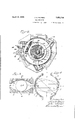
- Figure l is a diagrammatic sectional view of mechanism made in accordance with my invention.
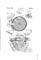
- F 2 is'a section on th line 22, Fig. 1;
- ig. 3 is a section on thiiline 3-3, Fig. 1;
- Fig. 4 is an enlarged fragmentary view. of the mechanism shown in Fig. 1; 2
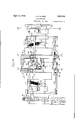
- Fig. 6 is a longitudinal vertical section through the mechanism shown in Fig. 5;
- Fig. 7 is a section on the line 7-7, Fig. 5;
- Fig. 8 is a sect-ionv on the line 88
- Fig. 5 is a section'on the line 9-9, Fig. 5;
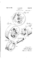
- Figs. 11,12,13, 14 and 15 are detached perspectives of various elements of the mechamsm;
- Fig. 16 is a section on the line 16-16, Fig. 5 I
- Figs. 17, 18, 19 and 20 are detached perspectives showing other elements of the mechamsm
- Fig.2l is an enlarged transverse sectional view similar to that of Fig. 7 illustrating a detail of the mechanism not shown in the preceding figure;
- Fig. 22 is reduced elevational view similar to that of Fi 5 illustrating the additional parts shown inig. 21;
- Fig. 23 is a fragmentary enlarged transverse sectional View similar to that of Fig. 9, illustrating a modification within the scope of the invention
- Fig.24 is a section on the line 24-24, Fig.
- Fig. 25 is a section on the-line 2525, Fig. 23
- Fig. 26 is a fragmentary elevational view illustrating a further modification of the invention.
- Fig. 27 is a section on the line 2727 Fig.
- a Fig. 28 is a detached fragmehtar perspective view illustrating a detail of t -e mechanism
- Fig. 29 is a section on the line 29-29, Fig. 2
- Figs. 1, 2 and 3 I have illustrated diagrammatically a known type of friction mechanism consisting of three major elements designated respectively 1, 2 and 3, the elements 1 and 2 having opposed faces in which are formed annular recesses 4 and 5 each of which in transverse section defines a segment of a circle and which together form opposite sides of a toroidal space between the elements 1 and 2.
- the element 3 comprises in the present instance a pair of wheels or disks 6 and 7 and a wheel-supporting structure 8, the Wheels being freely rotatable in their own planes and being confined between the elements 1 and 2 and within the recesses 4 and 5.
- the wheels 6 and 7 may be angularly adjusted from an intermediate position, shown in full lines in Figs. 1, 2 and 3, around axes A-A, see Figs. 2 and 3, to positions such as 6a, 7a and 6b, 7 6, shown in broken lines in Fig. 1.
- the positions of the wheels 6 and 7 are normally such that the planes of said wheels are tangent at the points where the wheels contact with the elements 1 and 2 with circles concentric with these elements.
- the direction and rapidity of the resultant movement on the axes AA is a function of the direction of the adjustment on the axes BB from the normal position and the extent of this adjustment.
- Fig. 4 shows, somewhat enlarged, the upper portion of the mechanism including the wheel 7.
- the wheel 7 assumes a position such as shown in full lines, in which it is freely rotatable about an axis YY. It may now be assumed that the wheel 7 is adjustedaround the axes BB to the broken line position designated by the numeral 7 This adjusted position of the wheel 7 and the corresponding adjustment of the wheel 6 are also indicated in broken lines in Fig. 2.
- the adjustment of the wheels 6 and 7 about the axes BB is in effect and in each instance a pivotal movement upon the two points of contact between the wheel and the elements 1 and 2. Accordingly, this adjustment is a simple one requiring little force to accomplish in contradistinction to the relatively great force required .under the same conditions to move the wheel from a normal position about the axis AA.
- the automatic action described above resulting from a simple adjustment of the wheels about the axes BB afi'ords a practicable means for obtaining an adjustment of the wheels about the last named axes practically independent of the amount of power transmitted and the pressure between the elements at the said points of contact.
- the direction of the movement on the axis A-A of the respective wheels is determinable by the direction in which the wheels are oscillated on their axes li -13 from the normal position.
- Figs. 5 to 20, inclusive I have illustrated an application of the aforedescribed mechanical device to a variable power transmission mechanism.
- This mechanism comprises ele ments 11 and 12 which while capable of limited relative movement, as hereinafter set forth, may be considered'as relatively fixed with respect to an intermediate rotary member 13.
- the member 13 is secured to and carried by a. shaft 14 journaled in bearings 9 in the fixed structure 10 of the mechanism and extending centrally through the element 12.
- each of the members 11 and 12 is provided with an annular recess 15, which cross sectionally constitutes a segment of a circle, and both faces of the intermediate member 13 are similarly recessed at 16 so that with the said member 13 predeterminedly spaced with respect to both of the members 11 and 12, the opposed recesses 15 and 16 define in each instance the opposite sides of a toroidal space between the elements 11 and 12 and the intermediate element 13.
- a yoke structure 17 Surrounding the intermediate member 13 is a yoke structure 17 comprising spider portions 18 and 19 which respectively extend inwardly between the members 11 and 12 and the opposite faces of the intermediate member 13.
- the spider 19 has a ball bearing 21 upon the shaft 14. while the spider 18 at its central portion is keyed to a second shaft 22 journaled in bearings 23 in the fixed structure 10 of the mechanism at the rear of the member 11 and which extends centrally through said member in alignment with the shaft 14.
- the shafts 14 and 22 are jointed as indicated at 24 to maintain the aligmnent and for the purpose of mutual support.
- the yoke 17 carries in each of the spider portions 18 and 19 three wheels or disks 25, 26 and 27 these wheels normally contacting with the member 13 and either one or other of the elements 11 and 12'and being so arranged between the elements and the member 13 that the center of rotation of each wheel lies approximately in the center line of the toroidal space formed by the recesses 15 and 16 which it occupies.
- each of the wheels comprises an outer rotary rim portion 28 and an axle portion 29, the rim portion operating upon ball bearings 31 interposed between these parts.
- the axle portion 29 of each of the wheels is mounted for pivotal movement upon trunnions 32, 32 of a cylindrical member 33, see Fig. 12, which latter is secured as by means of suitable pins 34,
- each of the members 35 is provided at its opposite ends with trun and 19 of the structure 17 consists of three radially projecting rectangular bracket portions 37 at the mnerends of which the support members 35 are mounted, and in the outer angles between these parts 37 are extensionbrackets 38.
- a'shaft 39 In each of these extension brackets 38 is journaled a'shaft 39.
- each of which carries adjacent the outer end thereof a pinion 41.
- the inner end of each of the shafts 39 which as shown in Fig.9 is journaled in one side of one or other of the brackets 37 is provided with an axial recess 42 for reception of one of the trunnions 36 of the box 35.
- each of the yokes is journaled in one side of the associated bracket 37, while the opposite end of the yoke is carried by the inner end of the shaft 39, each of these shafts having at its inner end a rectangular part 45 which fits into a correspondingly formed aperture 46 in the end of the bracket 44.
- Each of the axles 29 of the wheels 25, 26 and 27 is pro.- vided with an arm 47 which turns inwardly over the top of the associated bracket 35, and has at the top a pin 48 which in assembly occupies.
- a slot 49 formed in the present instance in a cylindrical projection 51 on the inner face and mid portion of the bracket 44. It will be noted that the slot 49 is formed at an acute angle to the axis of the trunnions 32.
- each'of the wheels 25, 26 and 27, in addition to its normal rotary movement upon the bearings 31, is afforded a pivotal movement in two directions at right angles to each other, one of these movements being about the axis of the trunnions 32 of the mem her 33 which it will be noted occupy planes normal to the plane of rotation of the member 13 and radial to the axis of said rotation, and the other movement being about the axis of the trunnions 36 of the wheel-supporting member 35, this axis being in a plane parallel to the plane of rotation of the said member 13.
- movement of the wheels about the axes BB results in a subsequent and automatic movement of the wheels upon their axes A-A, this adjustment about the axis A-A being now independent of the shaft 39.
- this adjustment or movement of the wheels about their axes AA following an initial adjustment through shaft 39 and yoke 44 of the wheels upon their axes B-B may result in an automatic re-adjustment of the wheels about their axes BB into a normal position in which the wheels are in equilibrium as regards their axes A-A.
- sleeves 52 and 53 Mounted externally upon the cylindrical end portions of the fixed structure 10 are sleeves 52 and 53. To the sleeve 52 are attached bars 54 which extend substantially parallel to the shaft 22 toward the mid section of the mechanism and have thereon racks 55 which respectively engage the pinions 41 associated with the wheels 25,26 and 27 of the spider 18. A corresponding set of bars 56 extend from the sleeve 53 and have thereon racks 57 which engage the pinions 41 associated with the wheels 25, 26 and 27 of the spider 19. The racked portions of the arms 54 and 56 are guided, as clearly illustrated in Figs.
- each corresponding pair of rods 54 and 56 are joined at their mid sections by bolts 50 to constitute a rigid link between the sleeves 52 and 53.
- the rods 54 are longitudinallly slotted for the bolts 50 providing for a relative longitudinal adjustment of the rods.
- the sleeve 52 is provided in the present instance with an annular groove 61 affording means for operatively associating therewith an operating member 62 whereby the sleeve may be adjusted axially upon the supporting structure 10.
- the sleeves 52 and 53 and the associated racks constitute a means for oscillating the shafts 39 to thereby oscillate the wheels 25, 26 and 27 about their axes B--B and constitute also an interconnection between these wheels such that they are maintained relatively in a predetermined fixed relation with respect to the elements 11, 12 and 13.
- the sleeves 52 and 53 and the associated racks also constitute as hereinafter set forth a means operative under certain conditions for oscillating the wheels.
- This brake comprises a brake band 63 which surrounds and is adapted to frictionally en gage the periphery of the member 13.
- One end of this band is connected at 64 to the yoke 17, while the other end is connected through a pin 65 with a lever 66 which is pivotally secured at 67 to a second lever 68.
- This lever 68 is pivotally secured at 69 to the yoke 17 and its upper end projects into the path of an extension 71 on the inner end of one of the bars 56.
- the arrangement is such that as the rack bars approach one end of theirpath of travel, the brake band is contracted so as to bind upon the periphery of the member 13, this for a purpose hereinafter set forth.
- Means is provided at 70 in the form of a set screw for adjusting the effective point of contact between the part 71 and the lever 68.
- a spring (not shown) may be utilized to maintain the band 63 normally free from the member 13.
- each of these projecting portions eing provided on its outer face with a series of inclined cam surfaces 7 3 which are adapted to engage similar inclined surfaces 74 upon 6 the abutting faces of the fixed structure 10.
- a spring 76 is provided which retains the elements 11 and 12 in an advanced position engaging the wheels 25, 26 and 27 with a predetermined initial pressure.
- these springs 76 are in each instance attached at one end to a pin 77 projecting from the outer faces of the members 11 and 12 and at the other end to an arm 78 secured to the fixed structure 10.
- the spring therefore, functions to so rotate the elements 11 and 12 that they move toward each other and against the wheels 25, 26 and 27.
- the shafts 14 and 22 are rotating in -a clockwise direction viewed from the righthand end of Fig. 6 and as illustrated by the arrow in Fig. 2
- the reaction of the wheels 25, 26 and 27 upon the elements 11 and 12 will tend to cause these elements to move in a counterclockwise direction, such movement of these elements by reason of the construction described above and illustrated in Figs.
- the device functions to automatically increase the pressure upon the wheels 25, 26 and 27 as the torque ratio increases. As the torque ratio decreases, the pressure will automatically readjust itself.
- Means is also provided for oscillating the elements 11' and 12 in a counterclockwise direction under predetermined cir cumstances to cause the elements to move away from and substantially release the wheels 25, 26 and 27
- each end of the fixed structure 10 is rovided with a pair of longitudinal cylin rical passages 81in which are rotatably mounted rods 82.
- Each of these rods has at its inner end a transverse arm 83 which. fits into a recess 84 in the outer face of the element 11 or 12, as the case may be, as illustrated in Figs. 6 and 16.
- Each of the rods 82 carries adjacent its opposite end a transverse pin 85 which projects outward- ⁇ Iythrough circumferential slots 86] in the xed structure 10 and beyond the outer surface of the latter.
- a sleeve -87 and 88 At each end of the mechanism and slidable on the fixed structure 10 is a sleeve -87 and 88 respectively, each of these having a pair of slots 89 for reception of the projecting ends of the pins 85, and these slotsbeing arranged at an acute angle to the circumferential direction whereby longitudinal movement of the sleeves on the member 16 will result in an oscillation of the rods 82.in one direction or other, depending nponthe direction of movement of the sleeves.
- the sleeves 87 and 88 are respectively in the paths of the collars or sleeves 52 and 53, and as these sleeves approach the limit of their movement towards the right, see Fig. 5, the collars 52 and 53 contact respectively with the sleeves 87 and 88,.moving said sleeves to the right and effecting an oscillation'of the rods 82 in a clockwise direction viewed from the right hand end of Fig. 6, or as indicated by the arrows in Fig. 16.
- the speed ratio is reduced approximately to unity.
- the member 13 and the oke 17 will retate at nearly. the same spec s. point, as later explained, that the band 63 comes into eifect to lock the member 13 and the yoke 17 together.
- Each of the extended trunnions carries at its outer end a pinion 151 which meshes with one of a corresponding number of racks 152 carried by an annular yoke 153 which entirely surrounds the structure 17 and has a bearing upon said structure, as indicated at 154.
- These bearings in the present instance include rollers which travel upon those portions of the structure 17 which extend between and connect the "spiders .18 and 19.
- the member 153 with its racks 152 is entirely free tomove in a direction axial of the shafts 14 and 22.
- the wheels 25, 26 and 27 are mounted on fixed axes in the respective supports 35, and the latter is carried by a ring 95, which latter is mounted for circumferential movement in suitable circular guides 96 formed in the spiders 18 and 19 of the member 17
- the ring 95 is provided on its periphery with a projecting circumferential ri 97, which fits in a correspondingly formed recess 98 in the member 96, as shown in Fig. 24.
- the member 35 is provided at each end with a trunnion 99, having fixed thereto a bevel pinion 101 which meshes with a suitable rack 102 on the ring 95, and the trunnion 99 projects beyond the pinion to enter va circumferential guide slot 103 in the inner face of the ring 95 whereby the member 35 is retained in the ring 95, while at the same time being capable of oscillation within and with respect to said ring.
- a thrust bearing 104 is provided at the outer end of each trunnion for engagement with the bottom of the slot 103. It will be noted by reference to Fig. 23 that the slots 103 are of limited length and control the relative movement of oscillation of the member 35 within the rin 95.
- the rack 102 at one side of the member 95 is arranged to engage the opposite side of the associated pinion from that engaged by the rack at the opposite side, so that there. is no opposition in the racks to the aforesaid oscillation of the member 35 in its supporting ring.
- Means for circumferentially moving the ring 95 in its supporting member 96, this means consisting of a rack 105, secured to the ring 95 at a point intermediate the racks 102 and at that side of the annulus furthest from the shaft 22 to which the spider 18 is secured, and a shaft 106 journaled, as shown in Fig. 25, in the spider 18 and projecting through a circumferential slot 110 in the ring 95, this shaft having at its inner end a bevel pinion 107 which meshes with the rack 105, and at its outer end a spur gear 108 which is engaged by the rack 55. Longitudinal movement of this rack results in the rotary movement of the shaft 106, and through the pinion 107 and rack 105 in the circumferential movement of the ring 95, the extent of which is limited by the length of the slot 110.
- the wheel 25 occupies the same relative position with respect to the cooperating parts as the corresponding wheel of the embodiment shown in Figs. 6 and 9. In this position, there is a predetermined torque and speed ratio, as previously set forth between the driving and driven elements.
- each of the members 35 is provided at its opposite ends with trunnions 99 having fixed thereto a bevel pinion 101 which meshes with a suitable rack 102 on the member 115.
- the racks 102 are provided at its opposite ends with trunnions 99 having fixed thereto a bevel pinion 101 which meshes with a suitable rack 102 on the member 115.
- the racks 102 are provided at its opposite ends with trunnions 99 having fixed thereto a bevel pinion 101 which meshes with a suitable rack 102 on the member 115.
- journaled recesses 117 formed in substantially rectangular blocks 118 which are movably mounted in circumferential recesses 119 in the opposite sides of the member 115.
- the trunnions 99 are provided with a flange 121 between which and the journal members 118 are inserted ball bearings 122, see Fig. 29.
- Roller bearings 123 are also provided for the journal blocks 118 in the bottoms of the recesses 119 which they occupy.
- each .of the members 115 is provided on its outer side with a pin 131 which projects radially through a circumferential slot 132 in the spider and into a slot 133 in a rod 134 which extends axially through a correspondingly formed opening in the spider.
- the rods 134 extend through both the spiders 18 and 19.
- These rods are the equivalent of the rack bars 54 of the mechanism previously de scribed and are secured through intervening bars 135 to the collar 52 in the same manner as are the bars 54 shown in Fig. 6.
- the slots 133 in the bars 134 into which the pins 131 of the various members 115 project are formed at an acute angle to the length of the bars themselves, so that longitudinal movement of the bars 134 must result in obvious manner in oscillation of the members 115.
- the mechanism operates as described above to cause an automatic resultant tipping of the wheels about their respective axes A-A to thereby vary the speed and torque ratios of the driving and driven parts, and this resultant adjustment of the wheels about their A-A axes also results through the pinions 101 and racks 102 and as described in the embodiment illustrated in Figs. 23 to 25, in a movement of the wheels about their axes BB in a direction reverse to the original tilting of these wheels through adjustment of the members 115.
- the entire adjustment movement stops when the wheels are again brought into a position in which, as in the position shown in Fig. 27, the planes of the wheels are tangential at the points of contact with the members 11, 12 and 13 to circles drawn through these points and concentric with the shaft 22.
- first of said rotarymembers and the reaction member havin opposed annular recesses defining a torroi al space concentric with the axis of rotation of the rotary members, a planetary transmission wheel carried by the second of said rotary members for frictional. contact with the first rotary member and the reaction member within said space, said wheel normally.
- each of said members having an annular recess concentric with the axis of the rotary member, which recesses define the opposite sides of a torroidal space between said members, a second rotary member, a planetary element carried by the second rotary member and contacting in said recesses with both the first-named rotary member and the reaction member, and means providing for adjustment of said planetary element to vary the relative positions with respect to the axis of the rotary members of the points of contact between the said element and the first-named rotary and reaction members and into a position where the speed ratio of the rotary members approaches unity, thereby permitting immobilization of the rotary members with respect to each other for a direct driving connection therebetween.
- one of said rotary members and the reaction member having opposed annular recesses defining a torroidal space concentric with the axis of the rotary members, and the other of said rotary members having a planetary wheel operative in the said space as a trans mission element cooperating with the reaction member and the driving member to produce rotation of the driven member, means for adjusting the wheel to vary the speed and torque ratios of the rotary members, and means actuated by said adjusting means for simultaneously separating the wheel and the reaction member and immobilizing with respect to each other the driving and driven members.
- a planetary transmission wheel carried by the second of said rotary members for frictionalcontact with the first rotary member and the reaction member within saidspace, said wheel normally occupying a position with its rotational axis in a plane containing the axis of rotation of said rotary members, a support for said wheel movable to afiord an adjustment of the wheel to vary the relative distances with respect to the axis of the rotary member of the points of contact between the wheel and the said members, a second support for the wheel pivotally movable to afi'ord an angular adjustment of the rotational axis of the wheel from the said normal plane, one of said supports being carried by the other, and a geared connection between said supports.
Landscapes
- Engineering & Computer Science (AREA)
- General Engineering & Computer Science (AREA)
- Mechanical Engineering (AREA)
- Friction Gearing (AREA)
Description
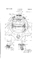
April 12, 193 J. s. SHARPE TRANSMISSION 9 Sheets-Sheet 1 Filed Dec. 11, 1928 J. S. SHARPE April 12, 1932.
TRANSMISSION Filed Dec.
April 12, 1932. 5, SHARPE 1,853,749
TRANSMISSION Filed Dec; 1928 9 Sheets-Sheet 3 April 12, J 3 SHARPE TRANSMISS ION Filed Dec. 11, 1928' 9 Sheets-Sheet 5 v April 12, 1932. J 5 SHARPE 1,853,749
TRANSMISSION Filed Dec. 11, 1928 9 Sheets-Sheet 6 J. S. SHARPE April 12, 1932.
TRANSMISSION 9 Sheets-Sheet '7 Filed Dec. 11, 1928 April 12, 1932.
.1. s. SHARPE TRANSMISSION Filed Dec. 11, 1928- 9 Sheets-Sheet 9 ZAL5-HZ%T v e? Patented Apr. 12, 1932 UNITED STATE-S JOHN SHARPE, OF HAVERFORD, PENNSYLVANIA TRANSMISSION Application filed December 1i; 192a. Serial No. a25,157.' v
The principal object of this invention is to provide a novel and useful mechanism in which a relatively simple adjustment of a movable member is utilized to effect and control a difi'erent and relatively difficult adjustment of the same member, and the invention further resides in the application of this device to transmission mechanism, as hereinafter set forth.
Another object of the invention therefore is. to provide an improved transmission mechanism capable of efficient operation in the transmission of relatively high powers and including practicable means for varying the ratio of the velocities of the driving and driven parts and of the torque input and output without appreciable power losses.
Another object is to provide variable torque-transfer mechanism in which the torque input to output ratio may be varied by a simple adjustment of a moving-part independently of the amount of torque involved, said adjustment being as readily accomplished during the transmission of high torques as in the transfer of torques of relatively low amplitude.
A more specific object is to provide a transmission mechanism of the type in which the velocity or torque ratios of driving and driven members is dependent upon the distance of the point of contact of one of said members with respect to the axis of rotation of the other, wherein provision is made for valying said distance and therefore the said ratio by a simple and easily effected adjustment of a contact element, the simplicity of said adjustment being practically unaffected by the amount ofpressure between the members at the point of contactand being capable of effecting said variation in the point of contact without diminution or modification of said pressure.
The invention further resides in certain novel and advantageous structural features 5 and arrangements of parts hereinafter set forth and illustrated in the attached drawings, in which:
Figure lis a diagrammatic sectional view of mechanism made in accordance with my invention;
ig. 3 is a section on thiiline 3-3, Fig. 1;
Fig. 4 is an enlarged fragmentary view. of the mechanism shown in Fig. 1; 2
Fig. 5. 's a side elevation of apractical 05 form of transmission mechanism embodying my invention;
Fig. 6 is a longitudinal vertical section through the mechanism shown in Fig. 5;
- Fig. 7 is a section on the line 7-7, Fig. 5;
Fig. 8 is a sect-ionv on the line 88, Fig. 5 Fig. 9 is a section'on the line 9-9, Fig. 5;
B Fig. lOis a section on the line 1010,
ig. 5; Figs. 11,12,13, 14 and 15 are detached perspectives of various elements of the mechamsm;
Fig. 16 is a section on the line 16-16, Fig. 5 I
Figs. 17, 18, 19 and 20 are detached perspectives showing other elements of the mechamsm;
Fig.2l is an enlarged transverse sectional view similar to that of Fig. 7 illustrating a detail of the mechanism not shown in the preceding figure;
Fig. 22 is reduced elevational view similar to that of Fi 5 illustrating the additional parts shown inig. 21;
Fig. 23 is a fragmentary enlarged transverse sectional View similar to that of Fig. 9, illustrating a modification within the scope of the invention;
Fig.24 is a section on the line 24-24, Fig.
Fig. 25 is a section on the-line 2525, Fig. 23
Fig. 26 is a fragmentary elevational view illustrating a further modification of the invention; 99
Fig. 27 is a section on the line 2727 Fig.
a Fig. 28 is a detached fragmehtar perspective view illustrating a detail of t -e mechanism, and
7Fig. 29 is a section on the line 29-29, Fig. 2
In Figs. 1, 2 and 3, I have illustrated diagrammatically a known type of friction mechanism consisting of three major elements designated respectively 1, 2 and 3, the elements 1 and 2 having opposed faces in which are formed annular recesses 4 and 5 each of which in transverse section defines a segment of a circle and which together form opposite sides of a toroidal space between the elements 1 and 2. The element 3 comprises in the present instance a pair of wheels or disks 6 and 7 and a wheel-supporting structure 8, the Wheels being freely rotatable in their own planes and being confined between the elements 1 and 2 and within the recesses 4 and 5. The wheels 6 and 7 may be angularly adjusted from an intermediate position, shown in full lines in Figs. 1, 2 and 3, around axes A-A, see Figs. 2 and 3, to positions such as 6a, 7a and 6b, 7 6, shown in broken lines in Fig. 1. V
In operation, one of the elements 1, 2, 3, may be relatively fixed, the others constituting respectively driving and driven parts. Assuming for example that the element 1 is relatively fixed and that the element 2 is 1'0- tated from a suitable power source about an axis XX, Fig. 1, it will be apparent that the wheels 6 and 7 will be rotated and made to travel in a circular path within the annular recess 4 of the relatively fixed member 1 with the result that structure 8 is also rotated about the axis XX and in the same direction as the element 2. The an ular velocity and torque ratios between the e ements 2 and 3 may be varied by adjusting the wheels 6 and 7 simultaneously and in opposite directions about their axes A-A.
In a device of this character, the positions of the wheels 6 and 7 are normally such that the planes of said wheels are tangent at the points where the wheels contact with the elements 1 and 2 with circles concentric with these elements. I have found that an adjustment from this normal position of the wheels 6 and 7 about axes BB at right angles to the axes A-A results in a rapid and automatic adjustment of the wheels about their respective axes A-A, this movement continuing until the wheels are readjusted about their axes BB into the aforesaid normal tangential positions. The direction and rapidity of the resultant movement on the axes AA is a function of the direction of the adjustment on the axes BB from the normal position and the extent of this adjustment.
The movement will best be understood by consideration of the diagrammatic view of Fig. 4, which shows, somewhat enlarged, the upper portion of the mechanism including the wheel 7. In normal operation, the wheel 7 assumes a position such as shown in full lines, in which it is freely rotatable about an axis YY. It may now be assumed that the wheel 7 is adjustedaround the axes BB to the broken line position designated by the numeral 7 This adjusted position of the wheel 7 and the corresponding adjustment of the wheel 6 are also indicated in broken lines in Fig. 2. It will be assumed further that the that side of the wheel which engages the relatively fixed element 1 will have a tendency to move toward the outer periphery of the recess 4, while the opposite side of the wheel engaging the driving element 2 will have a tendency to move oppositely toward the inner periphery of the recess 5. This tendency of the wheel to adjust itself about the axis A-A is not affected by the magnitude of the pressure exerted upon the wheel by the elements 1 and 2, and the wheel being free to adjust itself on the axis A-A, such adjust ment will actually occur. This is illustrated in Fig. 4, in which the direction and character of the movement is indicated by the brokenline position designated 7 that being one possible position of the wheel 7 in the aforesaid adjustment movement on the axis AA. Referring to Fig. 2,}; it should be noted that in practice the adjustment of the wheel 6 on itsaxis BB to position 6, corresponding to the aforedescribed adjustment of the wheel 7 to position 7', should be in the same direction as the latter adjustment so that the resulting movement of the wheel 6 on its axis AA will correspond to the same movement of the wheel 7 in that the side of the wheel contacting with element 1 will move toward the outer periphery of the groove 4, while the opposite side will move toward the inner periphery of the groove 5. As reviously stated, the movement on the axis A 0011- tinues until such time as the wheels return to a normal tangential position such for example as indicated at 7", Fig. 4,-in which position equilibrium of the parts is restored.
The adjustment of the wheels 6 and 7 about the axes BB is in effect and in each instance a pivotal movement upon the two points of contact between the wheel and the elements 1 and 2. Accordingly, this adjustment is a simple one requiring little force to accomplish in contradistinction to the relatively great force required .under the same conditions to move the wheel from a normal position about the axis AA. The automatic action described above resulting from a simple adjustment of the wheels about the axes BB afi'ords a practicable means for obtaining an adjustment of the wheels about the last named axes practically independent of the amount of power transmitted and the pressure between the elements at the said points of contact. Obviously, the direction of the movement on the axis A-A of the respective wheels is determinable by the direction in which the wheels are oscillated on their axes li -13 from the normal position.
In Figs. 5 to 20, inclusive, I have illustrated an application of the aforedescribed mechanical device to a variable power transmission mechanism. This mechanism comprises ele ments 11 and 12 which while capable of limited relative movement, as hereinafter set forth, may be considered'as relatively fixed with respect to an intermediate rotary member 13. The member 13 is secured to and carried by a. shaft 14 journaled in bearings 9 in the fixed structure 10 of the mechanism and extending centrally through the element 12. As shown in Fig. 6, the inner face of each of the members 11 and 12 is provided with an annular recess 15, which cross sectionally constitutes a segment of a circle, and both faces of the intermediate member 13 are similarly recessed at 16 so that with the said member 13 predeterminedly spaced with respect to both of the members 11 and 12, the opposed recesses 15 and 16 define in each instance the opposite sides of a toroidal space between the elements 11 and 12 and the intermediate element 13.
Surrounding the intermediate member 13 is a yoke structure 17 comprising spider portions 18 and 19 which respectively extend inwardly between the members 11 and 12 and the opposite faces of the intermediate member 13. The spider 19 has a ball bearing 21 upon the shaft 14. while the spider 18 at its central portion is keyed to a second shaft 22 journaled in bearings 23 in the fixed structure 10 of the mechanism at the rear of the member 11 and which extends centrally through said member in alignment with the shaft 14. At their inner ends, the shafts 14 and 22 are jointed as indicated at 24 to maintain the aligmnent and for the purpose of mutual support.
The yoke 17 carries in each of the spider portions 18 and 19 three wheels or disks 25, 26 and 27 these wheels normally contacting with the member 13 and either one or other of the elements 11 and 12'and being so arranged between the elements and the member 13 that the center of rotation of each wheel lies approximately in the center line of the toroidal space formed by the recesses 15 and 16 which it occupies. As shown in Figs. 6 and 13, each of the wheels comprises an outer rotary rim portion 28 and an axle portion 29, the rim portion operating upon ball bearings 31 interposed between these parts. The axle portion 29 of each of the wheels is mounted for pivotal movement upon trunnions 32, 32 of a cylindrical member 33, see Fig. 12, which latter is secured as by means of suitable pins 34,
' see Fig. 9, within an open-sided rectangular support member 35 which is shown in perspective in 11. Each of the members 35 is provided at its opposite ends with trun and 19 of the structure 17 consists of three radially projecting rectangular bracket portions 37 at the mnerends of which the support members 35 are mounted, and in the outer angles between these parts 37 are extensionbrackets 38. In each of these extension brackets 38 is journaled a'shaft 39. each of which carries adjacent the outer end thereof a pinion 41. The inner end of each of the shafts 39, which as shown in Fig.9 is journaled in one side of one or other of the brackets 37 is provided with an axial recess 42 for reception of one of the trunnions 36 of the box 35. the other trunnion of said box being journaled in one end 43 of ayoke 44 which longitudinally embraces the box. This end 43 of each of the yokes is journaled in one side of the associated bracket 37, while the opposite end of the yoke is carried by the inner end of the shaft 39, each of these shafts having at its inner end a rectangular part 45 which fits into a correspondingly formed aperture 46 in the end of the bracket 44. Each of the axles 29 of the wheels 25, 26 and 27 is pro.- vided with an arm 47 which turns inwardly over the top of the associated bracket 35, and has at the top a pin 48 which in assembly occupies. a slot 49 formed in the present instance in a cylindrical projection 51 on the inner face and mid portion of the bracket 44. It will be noted that the slot 49 is formed at an acute angle to the axis of the trunnions 32.
From the foregoing description, it will be apparent that each'of the wheels 25, 26 and 27, in addition to its normal rotary movement upon the bearings 31, is afforded a pivotal movement in two directions at right angles to each other, one of these movements being about the axis of the trunnions 32 of the mem her 33 which it will be noted occupy planes normal to the plane of rotation of the member 13 and radial to the axis of said rotation, and the other movement being about the axis of the trunnions 36 of the wheel-supporting member 35, this axis being in a plane parallel to the plane of rotation of the said member 13. The last named of these axes corresponds to the axis AA of the foregoing description, while the axis of the trunnions 32corresponds to the axis previously designated BB. The movement of the wheels about their respective axes B-B is a limited one determined in the present instance by set screws 40 in the eleshaft 39 by reason of the operative connection between this shaft and the yoke 44.
Assuming as in practice a pressure exerted at diametrically opposite points on the respective wheels by the elements 11 and 12 and member 13, it will be apparent that any oscillation of the shafts 39 will result in a movement of the yoke 44 and a consequent oscillation through the cam slot 49 and pin 48 of the associated wheel or disk about its axis B-B. During this movement, there is no tendenc of the Wheels to move about their axes A by reason of the frictional contact at the opposite sides of the wheel with the member 13 and the elements 11 or 12. The points of contact of these parts upon the wheels, however, being in alignment with the axis BB, the frictional resistance to movement about this axis is practically negligible. As set forth above, movement of the wheels about the axes BB results in a subsequent and automatic movement of the wheels upon their axes A-A, this adjustment about the axis A-A being now independent of the shaft 39. As hereinafter explained in greater detail, this adjustment or movement of the wheels about their axes AA following an initial adjustment through shaft 39 and yoke 44 of the wheels upon their axes B-B may result in an automatic re-adjustment of the wheels about their axes BB into a normal position in which the wheels are in equilibrium as regards their axes A-A.
Mounted externally upon the cylindrical end portions of the fixed structure 10 are sleeves 52 and 53. To the sleeve 52 are attached bars 54 which extend substantially parallel to the shaft 22 toward the mid section of the mechanism and have thereon racks 55 which respectively engage the pinions 41 associated with the wheels 25,26 and 27 of the spider 18. A corresponding set of bars 56 extend from the sleeve 53 and have thereon racks 57 which engage the pinions 41 associated with the wheels 25, 26 and 27 of the spider 19. The racked portions of the arms 54 and 56 are guided, as clearly illustrated in Figs. 5 and 9, in the bracket extensions 38 of the brackets 37 in which the shafts 39 are journaled, and in the present instance each corresponding pair of rods 54 and 56 are joined at their mid sections by bolts 50 to constitute a rigid link between the sleeves 52 and 53. As shown in Fig. 5, the rods 54 are longitudinallly slotted for the bolts 50 providing for a relative longitudinal adjustment of the rods. The sleeve 52 is provided in the present instance with an annular groove 61 affording means for operatively associating therewith an operating member 62 whereby the sleeve may be adjusted axially upon the supporting structure 10. It will be noted that the sleeves 52 and 53 and the associated racks constitute a means for oscillating the shafts 39 to thereby oscillate the wheels 25, 26 and 27 about their axes B--B and constitute also an interconnection between these wheels such that they are maintained relatively in a predetermined fixed relation with respect to the elements 11, 12 and 13. The sleeves 52 and 53 and the associated racks also constitute as hereinafter set forth a means operative under certain conditions for oscillating the wheels.
25, 26 and 27 simultaneously about their re-' spective axes A-A. It will be noted that whereas the racks 55 engage one side of the associated pinions 41, the racks 57 are so arranged as to engage the opposite sides of their associated pinions whereby the direction of the oscillation of the wheels 25, 26 and 27 of the spider 18 about their axes AA as the direct result of any movement of the aforesaid racks will be opposite to the corresponding movement of the wheels 25, 26 and 27 of the spider 19 about their axes A--A. The initial adjustment movement of the wheels of the spider 18 about their axes B-B must, however, be in the same direction as the corresponding movement about their axes B-B of the wheels of the spider 19, and this is accomplished by having the cam slots 49 controlling the two sets of wheels at opposite angles.
By reference to Figs. 5, 6 and 10, it will be noted that I provide brake mechanism in conjunction with the driving member 13. This brake comprises a brake band 63 which surrounds and is adapted to frictionally en gage the periphery of the member 13. One end of this band is connected at 64 to the yoke 17, while the other end is connected through a pin 65 with a lever 66 which is pivotally secured at 67 to a second lever 68. This lever 68 is pivotally secured at 69 to the yoke 17 and its upper end projects into the path of an extension 71 on the inner end of one of the bars 56. The arrangement is such that as the rack bars approach one end of theirpath of travel, the brake band is contracted so as to bind upon the periphery of the member 13, this for a purpose hereinafter set forth. Means is provided at 70 in the form of a set screw for adjusting the effective point of contact between the part 71 and the lever 68. A spring (not shown) may be utilized to maintain the band 63 normally free from the member 13.
In the transmission of power by mechanism of this type, pressure must be exerted upon opposite sides of the wheels or disks 25, 26 and 27 so that there may be no slippage between the transmission elements 11, 12 and 13, and this pressure shall preferably vary with the torque or turning moment of the driven parts. I have provided means whereby the operating pressure upon the wheels 25, 26 and 27 will so automatically vary. The mechanism is best illustrated in Figs. 5, 6, 8, and 16 to 20, inclusive. It will be noted therein that each of the members 11 and 12 is proneeavae' A f .5
vided at its outer side with a cylindrical pro- 'ection 72, each of these projecting portions eing provided on its outer face with a series of inclined cam surfaces 7 3 which are adapted to engage similar inclined surfaces 74 upon 6 the abutting faces of the fixed structure 10.
.It will be noted that the elements 11 and 12 are in each instance supported upon a hollow cylindrical extension 75 of the fixed structure 10. With the inclined surfaces 73 and 74 in contact, it will be apparent that any angular movement of the elements 11 and 12 will result in a corresponding axial movement either towards or away from the member 13. In each instance, a spring 76 is provided which retains the elements 11 and 12 in an advanced position engaging the wheels 25, 26 and 27 with a predetermined initial pressure.
As illustrated in Figs; 5, 6 and 17, these springs 76 are in each instance attached at one end to a pin 77 projecting from the outer faces of the members 11 and 12 and at the other end to an arm 78 secured to the fixed structure 10. The spring, therefore, functions to so rotate the elements 11 and 12 that they move toward each other and against the wheels 25, 26 and 27. Assuming that the shafts 14 and 22 are rotating in -a clockwise direction viewed from the righthand end of Fig. 6 and as illustrated by the arrow in Fig. 2, it will be apparent that the reaction of the wheels 25, 26 and 27 upon the elements 11 and 12 will tend to cause these elements to move in a counterclockwise direction, such movement of these elements by reason of the construction described above and illustrated in Figs. 17 and 18 causing the elements to move inwardly toward each other and to bear withincreased pressure against the outer sides of the wheels 25, 26 and 27. The greater the power being transmitted and the higher the torque ratio, the greater will be this reaction of the said wheels upon the elements 11 and 12 and the greater will be the pressure of the elements upon the wheels. The device, therefore, functions to automatically increase the pressure upon the wheels 25, 26 and 27 as the torque ratio increases. As the torque ratio decreases, the pressure will automatically readjust itself.
Means is also provided for oscillating the elements 11' and 12 in a counterclockwise direction under predetermined cir cumstances to cause the elements to move away from and substantially release the wheels 25, 26 and 27 As shown in Fig. 6, each end of the fixed structure 10 is rovided with a pair of longitudinal cylin rical passages 81in which are rotatably mounted rods 82. Each of these rods has at its inner end a transverse arm 83 which. fits into a recess 84 in the outer face of the element 11 or 12, as the case may be, as illustrated in Figs. 6 and 16. Each of the rods 82 carries adjacent its opposite end a transverse pin 85 which projects outward- }Iythrough circumferential slots 86] in the xed structure 10 and beyond the outer surface of the latter. At each end of the mechanism and slidable on the fixed structure 10 is a sleeve -87 and 88 respectively, each of these having a pair of slots 89 for reception of the projecting ends of the pins 85, and these slotsbeing arranged at an acute angle to the circumferential direction whereby longitudinal movement of the sleeves on the member 16 will result in an oscillation of the rods 82.in one direction or other, depending nponthe direction of movement of the sleeves. The sleeves 87 and 88 are respectively in the paths of the collars or sleeves 52 and 53, and as these sleeves approach the limit of their movement towards the right, see Fig. 5, the collars 52 and 53 contact respectively with the sleeves 87 and 88,.moving said sleeves to the right and effecting an oscillation'of the rods 82 in a clockwise direction viewed from the right hand end of Fig. 6, or as indicated by the arrows in Fig. 16. By reason of the engagement of the arms 83 with one side of the slot 84, the members 11 and 12 will be oscillated in a clockwise direction, which will have the effect of relieving the pressure there-- of upon the wheels 25, 26 and 27 It will be noted also that it is at this end of the travel of the collars 52 and 53 that the band 63 is tightened upon the element 13, so that the The operation of the device is as follows Rotation of theshaft 14 in a clockwise direction viewed from the right hand end of Fig. 6 and with the parts as shown in that figure results in a rotation of the wheels 25, 26 and 27 with which the member 13 is in contactand a consequent rotation of the yoke 17 also in a clockwise direction by reason of the contact between the wheels and the relatively fixed elements 11 and 12 upon which the said wheels track. With the wheels as shown in Fig. 6, the ratio of angular velocity as well as the torque transfer ratio between the driving member 13 and the driven member 17 is approximately 2 to 1. If the wheels are pivoted on their axes A A, see Figure 6, intothe positions indicated by the broken lines designated by the reference numeral 91, this ratio is increased to a maximum, while with an adjustment of the wheels into an opposite position, as indicated by the broken lines 92,
the speed ratio is reduced approximately to unity. In other Words in this latter position, the member 13 and the oke 17 will retate at nearly. the same spec s. point, as later explained, that the band 63 comes into eifect to lock the member 13 and the yoke 17 together.
Assuming that the aforedescribed transmission is operating asillustrated in Fig. 6 and it is desired to decrease-the s eed ratio or to increase the angular speed 0 the yoke 17, the collar 52 through the operating lever 62 will be shifted tothe right, see Figs. 5 and 6. This movement of the collar 52 through the racks 55 and 57 will have the effect through the pinions 41, shafts 39, yokes 44 and cams 48 and 49 of oscillating the Wheels 25, 26 and 27 of both sets about their axes B B in a clockwise direction, see Figs. 7 and 9. As a result of this adjustment of the wheels, they will immediately begin to track toward the position 92. If after the initial movement of the lever 62 to oscillate the wheels about their axes B to a maximum extent the lever 62 is held stationary, the wheels will oscillate about their axes A toward the position designated 92 in Fig. 6 only until the pins 48 have moved back in the cam slots- 49 sufliciently far to bring the wheels into a normal planes 0 the wheels are tangent at the points of contact with the elements 11, 12 and 13 to circles concentric with these elements. If pressure is continued upon the operating lever 62 to maintain the oscillated position of the wheels 25, 2 6 and 27 about their axes V BB, the movement on the axes A-A will taneously the brake 63 grips the'member 13,
thereby locking the latter member with the yoke 17 and creating a direct drive between the shafts 14 and 22.
Assuming that the transmission of power is interrupted while the wheels are in this high speed position and it is desired in restarting to move the wheels into the low speed 'or high torque ratio position designated by the numeral 91, it will be apparent that this may be. accomplished through the medium of the operating lever 62 by shifting the collar 52 to the extreme left hand position, Fig. 6. At the beginning of this return movement, the pressure of the elements 11 and 12 upon the wheels is practically negligible,
and at no time does it exceed the initial relatively slight-pressure exerted by the spring 76, so that with the mechanism inoperative,
It is at this osition of equilibrium where the.
' rection.
there is no difiiculty in shifting the wheels bodily from the angular position 92 tothe opposite angular position 91. In normal operation in effecting an increase in the speed or torque ratios and a decrease in the actual angular velocity of the member 17 from the intermediate position as shown in Fig. 2, a movement to the left of the collar 52 will accomplish the desired result, such movement initially effecting an oscillation of the wheels about their axes B B in a counterclockwise direction, Fig. 9, and a corresponding automatic movement of the wheels towards the position designated 91 in Fig. 6.
Ordinarily where the maximum movement of the wheels about their axes BB is a relatively small one, it will be unnecessary to provide special means for unifying this movement of the wheels of the respective spi- I ders and individually in the two sets. Un-
der certain circumstances, however, it may be desirable to have such unification, and the aforedescribed mechanism lends itself readily to such device. This is illustrated in Figs. 21 and 22. As shown in the first of these figures, which corresponds to the sectional view of Fig. 7 and in which the corresponding parts are designated by the same reference numerals as previously used, the mechanism is in all respects as described above, with the exception that the shafts 39 are in the present instance made hollow and the trunnion 36 at that end of each of the supports 35 is extended through the hollow shaft to the outside of the extension brackets 38. Each of the extended trunnions carries at its outer end a pinion 151 which meshes with one of a corresponding number of racks 152 carried by an annular yoke 153 which entirely surrounds the structure 17 and has a bearing upon said structure, as indicated at 154. These bearings in the present instance include rollers which travel upon those portions of the structure 17 which extend between and connect the "spiders .18 and 19. The member 153 with its racks 152 is entirely free tomove in a direction axial of the shafts 14 and 22. It will be noted that the racks 152 which engage the pinions associated with the respective sets of wheels engage these pinions on opposite sides so that in any movement of the member 153, the pinions of one set of wheels must turn in an opposite direction from the pinions of the other set, the angular movement of the supports 35 of the two sets of wheels responsible for such movement being also in the opposite di- The corresponding tilting movement of the wheels 25, 26 and 27 of both spiders is accordingly in the same direction. It will be apparent that this device functions to unify all movements of the wheels 25, 26 and 27 about their axes'B-B so that these Wheels be ma e without departure from the essential features of the invention, such for example as illustrated in Figs. 23, 24 and 25, in which corres onding parts of the mechanism are identifie by the same reference charactersused on the aforedescribed embodiment. In this instance, the wheels 25, 26 and 27 are mounted on fixed axes in the respective supports 35, and the latter is carried by a ring 95, which latter is mounted for circumferential movement in suitable circular guides 96 formed in the spiders 18 and 19 of the member 17 In the present instance, the ring 95 is provided on its periphery with a projecting circumferential ri 97, which fits in a correspondingly formed recess 98 in the member 96, as shown in Fig. 24. Also as illustrated, the member 35 is provided at each end with a trunnion 99, having fixed thereto a bevel pinion 101 which meshes with a suitable rack 102 on the ring 95, and the trunnion 99 projects beyond the pinion to enter va circumferential guide slot 103 in the inner face of the ring 95 whereby the member 35 is retained in the ring 95, while at the same time being capable of oscillation within and with respect to said ring. A thrust bearing 104 is provided at the outer end of each trunnion for engagement with the bottom of the slot 103. It will be noted by reference to Fig. 23 that the slots 103 are of limited length and control the relative movement of oscillation of the member 35 within the rin 95. It will also be noted that the rack 102 at one side of the member 95 is arranged to engage the opposite side of the associated pinion from that engaged by the rack at the opposite side, so that there. is no opposition in the racks to the aforesaid oscillation of the member 35 in its supporting ring.
Means is provided for circumferentially moving the ring 95 in its supporting member 96, this means consisting of a rack 105, secured to the ring 95 at a point intermediate the racks 102 and at that side of the annulus furthest from the shaft 22 to which the spider 18 is secured, and a shaft 106 journaled, as shown in Fig. 25, in the spider 18 and projecting through a circumferential slot 110 in the ring 95, this shaft having at its inner end a bevel pinion 107 which meshes with the rack 105, and at its outer end a spur gear 108 which is engaged by the rack 55. Longitudinal movement of this rack results in the rotary movement of the shaft 106, and through the pinion 107 and rack 105 in the circumferential movement of the ring 95, the extent of which is limited by the length of the slot 110.
It will be understood that although only that portion of the spider 18 which carries the wheel 25 is illustrated, the spider is so formed as to support in the same manner the wheels 26 and 27 in the same relative arrangement .as described in the previous embodiment and as shown in Fig. 9. Each of the wheels 26 and 27 has the same mounting as described above in connection with the wheel 25, and each of the associated pinions 108 is operatively connected with one of the racks 55. In
all other respects, the mechanism is the same as that described above and illustrated in Figs. 5 to 20, inclusive.
- In describing the action of the modified mechanism shown in Figs. 23 and 25, it should be noted that the wheel 25 occupies the same relative position with respect to the cooperating parts as the corresponding wheel of the embodiment shown in Figs. 6 and 9. In this position, there is a predetermined torque and speed ratio, as previously set forth between the driving and driven elements. Adjustment of the wheel 25 (and of the wheels 26 and 27) is accomplished about the axes of their trunnions 99, in order to vary the aforesaid ratios of speed and torque, by movement of the rack 55, which angularly shifts the ring 95, carrying with it the members 35 and the wheel supported therein whereby the said wheel is tilted about an axis at right angles to the axis through the trunnions of the member 35 and intersecting the points of contact between the said wheel and the opposed cooperating members 11 and 13, or 12 and 13,-as the case may be. Tilting of the Wheel in this manner results, as previously set forth, in an automatic movement of the wheel about an axis through the trunnions g 99. In this latter movement, the pinions 101 turning in the racks 102 cause a further oscillation of the members 35 and of the wheels carried thereby about their axes through the points of contact with the members 11, 12 and 13 in a direction opposite to the original movement about this axis resulting from the manipulation of the racks 55, and as a result of this opposite movement of oscillation, the wheels 25 are returned to a normal position in which the planes of the wheels are tangential at the points of contact between the wheels and the members 11, 12 and 13 with circles concentric with these members, this being, as previously described, the normal position of the Wheels with respect to said members.
It will accordingly be seen that the operation of this device is essentially the same as far as the results obtained as that of the mechanism illustrated in the preceding figures of the drawings. It will be noted, however, that whereas in the previously described embodiment the member 35 which supports the wheel 25 remains on a fixed axis, the wheel itself being oscillatable in this member to afford the controlled movement of the wheel which results in the movements of the latter to vary the speed and torque ratios, the wheels in the embodiment shown in Figs. 23,
24 and 25 are mounted on fixed axes in the support members 35, while these latter members are themselves movable about the two axes at right angles to. each other necessary for an operation of the device in accordance with the principles of the invention.
The invention is capable of still further embodiments and ramifications.
It will be noted that by reason of the double construction of the mechanism illustrated in Figs. 5 to 20, inclusive, in which a driving member 13 is interposed between the two reacting members 11 and 12, the axial thrusts of the entire mechanism are completely balanced. The thrusts, for example, of the members 11 and 12 upon the wheels 25, 26 and 27 are balanced in their effect upon the intermediate member 13. This not only is a decided mechanical or operatitve advantage, but simplifies the construction by avoidance of all unbalanced forces and the necessity for special means for offsetting such unbalance. Also the multiple arrangement described provides an increased effective contact between the driving and driven parts, which is particularly desirable in the transmission of high powers. The device is capable of still further multiplication of the essential operating parts to still further increase the effective operative contact between the driving and driven members.
Ordinarily where the maximum movement of the wheels about their axes BB is a relatively small one, it will be unnecessary to provide special means for unifying this move ment among the wheels of the respective spiders and in the two sets of wheels. Under some circumstances, it may be desirable, however, to have such unification, and in Figs. 26 to 29, inclusive, I have illustrated one method for accomplishing this result. In this instance, as in the modification shown in Figs. 23 to 25, inclusive, I have designated the parts of the mechanism corresponding to the parts of the aforedescribed mechanism by the same reference numerals. In each instance, these parts are indentical in function and substantially the same in form.
Referring to Fig. 27, which is a sectional view similar to that of Fig. 7 the wheels 25, 26 and 27, of which the foremost alone is shown, are mounted, as in the embodiment of Fig. 23, on fixed axes in their respective supports'35. Also as in the embodiment of Fig.
23, each of the supports 35 is carried by a member 115, which corresponds to the member 95 of said embodiment and which like that member is mounted for oscillation in a circular guide 116, these guides being formed, as shown, in the spiders 18 and 19.
As in the embodiment of Fig. 23, each of the members 35 is provided at its opposite ends with trunnions 99 having fixed thereto a bevel pinion 101 which meshes with a suitable rack 102 on the member 115. The racks 102.
in the resent instance are formed in brackets secure to and projecting inwardly from the member 115. The trunnions 99 project beyond the racks 102 and into journaled recesses 117 formed in substantially rectangular blocks 118 which are movably mounted in circumferential recesses 119 in the opposite sides of the member 115. The trunnions 99 are provided with a flange 121 between which and the journal members 118 are inserted ball bearings 122, see Fig. 29. Roller bearings 123 are also provided for the journal blocks 118 in the bottoms of the recesses 119 which they occupy. Each of the journal members 118 has a stem 124 which projects through a slot 125 in the bottom of the recess 119 and through a corresponding slot 126 in the spider 18 or 19, as the case may be. The extremities of each of the associated pairs of the stems 124 enter circular openings 127 in the opposite ends of a curved bar 128, which is slidably mounted in a circumferential groove 129 in the circular portions of the spiders 18 and .19 in which the members 115 are mounted. It will be understood that the mounting of each of the wheels 25, 26 and 27 of the respective spiders is identical with that described above, and that the description throughout is accordingly limited to one wheel only. The function of the member 128 will be set forth hereinafter.
As in the embodiment shown in Fig. 23, means is provided for simultaneously oscillating the members 115 to thereby shift the wheels about the axes previously designated BB.' In the present instance, each .of the members 115 is provided on its outer side with a pin 131 which projects radially through a circumferential slot 132 in the spider and into a slot 133 in a rod 134 which extends axially through a correspondingly formed opening in the spider. 'As shown in Fig. 26, the rods 134 extend through both the spiders 18 and 19. These rods are the equivalent of the rack bars 54 of the mechanism previously de scribed and are secured through intervening bars 135 to the collar 52 in the same manner as are the bars 54 shown in Fig. 6. The slots 133 in the bars 134 into which the pins 131 of the various members 115 project are formed at an acute angle to the length of the bars themselves, so that longitudinal movement of the bars 134 must result in obvious manner in oscillation of the members 115.
It will be apparent that the adjustment of the wheels 25, 26 and 27 of both sets about their axes B-B is a simultaneous one. The slots 133 which control the wheels of one spider are parallel to the slots in said bars which control the movement of the wheels of the other spider, so that the tilting of the 'wheels about their axes B--B is always in the same direction.
Following the oscillation of the members 115 as described above and the consequent tilting of the wheels 25, 26 and 27 about their axes BB, the mechanism operates as described above to cause an automatic resultant tipping of the wheels about their respective axes A-A to thereby vary the speed and torque ratios of the driving and driven parts, and this resultant adjustment of the wheels about their A-A axes also results through the pinions 101 and racks 102 and as described in the embodiment illustrated in Figs. 23 to 25, in a movement of the wheels about their axes BB in a direction reverse to the original tilting of these wheels through adjustment of the members 115. The entire adjustment movement stops when the wheels are again brought into a position in which, as in the position shown in Fig. 27, the planes of the wheels are tangential at the points of contact with the members 11, 12 and 13 to circles drawn through these points and concentric with the shaft 22. This action and the various movements will be readily understood from the foregoing description.
It will be noted that the tilting movement of the members 115 through the medium of the bars 134 results in the longitudinal movement in their grooves of the members 128. Each of these members is provided with an inwardly pro jecting radial pin 136, which pro jects through a radial and circumferential slot 137 in the spider which carries its supporting member and into a slot 138 in an arm 139 which is slidably fitted in a correspondingly formed guide groove 141 in the said spider. The arms 139, as shown in Figs-26 and 28 are carried by a floating ring 142 which encircles the member 13, the arms 139 projecting axially and oppositely into the grooves 141 provided for their reception in the said spiders 18 and 19. The ring 142 is entirely free to move in an axial direction, while being relatively fixed angularly with respect to the spiders 18 and 19 and the member 17 of which these spiders form a part.
As shown in Fig. 28, the slots 138 are ar-' ranged at an acute angle to the axial direction so that any movement of the members 128 in their guide grooves results through the pin 136 and the angular slots 138 in an axial movement of the entire member 142. Obviously, this member 142 functions to fix the relative positions about their axes BB of the wheels 25, 26 and 27, since one of these wheels cannot have movement about its axis without a corresponding movement of all the other wheels.
The operation of the mechanism shown in Figs. 26 to 29, inclusive, is essentially the same as the mechanism shown in the preceding figures, and differs from the previously described mechanism only in the inclusion of means for unifying the adjustment movement of the wheels 25, 26 and 27 about their axes BB.
I claim:
1. The combination with a rotary member, of a pair of relatively fixed members at opposite sides of said first member and spaced apart therefrom in an axial direction, a second rotar member having rotary elements confined etween the first rotary member and each of said axially spaced relatively fixed members and constituting a driving connection between said rotary members, means operating through said relatively fixed members for creating an axial thrust compressing said rotary elements between the first rotary member and said relatively fixed members, and means for synchronously moving said rotary elements to vary the speed and torque ratios of the rotary members.
2. The combination with a pair of coaxial rotary members, of a reaction member, the first of said rotary members and the reaction member having opposed annular recesses defining a torroidal space concentric with the axis of rotation of the rotary members, a planetary transmission wheel carried by the second of said rotary members for frictional contact with the first rotary member and the reaction member within said space, a support for said wheel pivotally movable in said second rotary member on an axis substantially parallel to the planes of rotation of the rotary members and tangent to a circle concentric with said members, a second support for said wheel pivotally movable within the support first named on an axis which lies at right angles to the pivotal axis of the'firstmamed support and in a plane containing the axes of the rotary members, and means for adjusting the said second support about its axis, including a member movable about an axis corresponding to the pivotal axis of the first-named support, together with a cam operatively connecting said adjusting member and said second support.
3. The combination with a rotary member, of a second rotary member, a planetary wheel carried by said second member and contacting with the first member, a member adapted to react with said wheel to afford actuation of one rotary member by the other through the medium of said wheel, said first rotary member and the reaction member having opposed annular recesses defining a torroidal space concentric with the axis of rotation of the rotary members, within which space the said wheel operates, a support for said wheel pivotally movable in said second rotary member on an axis substantially parallel to the planes of rotation of the rotary members and tangent-tea circle concentric with said members, a second support for said wheel pivotally movable within the support first named on an axis which lies at right angles to the pivotal axis of the first-named support and in a plane containing the axes of the rotary members, means for adjusting the said second support about its axis, including a member movable about an axis corresponding to the pivotal axis of the firstnamed support, together with a cam operatively connecting said adjusting member and said second support, a shaft connected with said adjusting member, an actuating member movable axially of the rotary members, and means whereby said axial movement efi'ects oscillation of the shaft.
4. The combination with a pair of coaxial rotary members, of a reaction member, the first of said rotary members and the reaction member having opposed annular recesses defining a torroidal space concentric with the axis of rotation of the rotary members, a planetary transmission wheel carried by the second of said rotary members for frirtional contact with the first rotary member and the reaction member within said space, said wheel normally occupying a position with its rotational axis in a plane containing the axis of rotation of said rotary members, a support for said wheel movable to afford an adjustment of the wheel to vary the relative distances with respect to the axis of the rotary member of the points of contact between the wheel and the said members, a second support for the wheel pivotally movable to afford an angular adjustment of the rotational axis of the wheel from the said normal plane, one of said supports being carried by the other, and means whereby movement of the first-named support resulting from a prior ivotal movement of the second support e ects an automatic return of'the wheel to the normal position from which it was moved by the said pivotal movement of the second support.
5. The combination with a pair of coaxial rotary members, of a reaction member, the
, first of said rotarymembers and the reaction member havin opposed annular recesses defining a torroi al space concentric with the axis of rotation of the rotary members, a planetary transmission wheel carried by the second of said rotary members for frictional. contact with the first rotary member and the reaction member within said space, said wheel normally. occupying a position with its rotational axis in a plane containing the axis of rotation of said rotary members, a support for said wheel pivotally movable to afl'ord an adjustment of the wheel to vary the relative distances with respect to the axis of the rotary member of the points of con-- tact between the wheel and the-said members, a second support for the wheel pivotally movable to afiord an angularadjustment of the rotational axisof the wheel from the said normal plane, one of said supports being carried by the other, and an operative adjustable connection between the'supports for auto-- matically returning the wheel to the normal position'from which it was moved by the said pivotal movement of the second support.
said members, and means for immobilizing the said members with respect to each other.
7. The combination with a rotary driving member, of a rotary driven member concentric with the driving member, a planetary transmission element carried by one of said members and operatively engaging the other, means adapted to react with said element to afford actuation of the driven member by the driving member through the medium of said element, said element being adjustable to vary the speed and torque ratios of the said members, and means eflective in a predetermined adjusted position of said element to immobilize the said members with respect to each other.
8. The combination with a rotary driving member, of a rotary driven member, a reaction member, a planetary transmission element carried by one of said rotary members and contacting with the other rotary member, said element also being adapted to react with the reaction member whereby rotation of the driving member may result in a rotation of the driven member, means for adjustmg the transmission element to vary the relative-positions with respect to the axis of the rotary members of the points of contact with the reacting and opposed rotary member, and means for rendering the reacting member inoperative and for immobilizing said rotary members with respect to each other.
9. The combination with a rotary driving member, of a rotary driven member, a planetary element constituting transmission means between said members, means adapted to react with said element to afiord actuation of the driven member by the driving member through the medium of said element, means for adjusting said element to vary the speed and torque ratios of the driving and driven members and means for relatively immobilizing said members whereby the driven element is in direct driving relation with the driving element.
10; The combination with a rotary driving member, of a rotary driven member, a planetary element constituting transmission means between said members, means adapted to react with said element to afford actuation of the driven member by the driving member through the medium of said element, and means providing for adjustment of said planetary element to vary the speed and torque ratios ofthe driving and driven elements and into a position permitting rela- .tive immobilization of the driving and driven members for a direct driving relation therebetween. l
llfThe combination with a rotar member, of a reaction member axially spaced therefrom, each of said members having an annular recess concentric with the axis of the rotary member, which recesses define the opposite sides of a torroidal space between said members, a second rotary member, a planetary element carried by the second rotary member and contacting in said recesses with both the first-named rotary member and the reaction member, and means providing for adjustment of said planetary element to vary the relative positions with respect to the axis of the rotary members of the points of contact between the said element and the first-named rotary and reaction members and into a position where the speed ratio of the rotary members approaches unity, thereby permitting immobilization of the rotary members with respect to each other for a direct driving connection therebetween.
12. The combination with rotary driving and driven members and a reaction member,
one of said rotary members and the reaction member having opposed annular recesses defining a torroidal space concentric with the axis of the rotary members, and the other of said rotary members having a planetary wheel operative in the said space as a trans mission element cooperating with the reaction member and the driving member to produce rotation of the driven member, means for adjusting the wheel to vary the speed and torque ratios of the rotary members, and means actuated by said adjusting means for simultaneously separating the wheel and the reaction member and immobilizing with respect to each other the driving and driven members.
13. The combination with rotary driving and driven members and a reaction member, one of said rotary members and the reaction member having opposed annular recesses defining a torroidal space concentric with the axis of the rotary members, and the other of said rotary members having a planetary wheel operative in the said space as a transmission element cooperating with the reaction member and the driving member to produce rotation of the driven member, means for adjusting the wheel to vary the speed and torque ratios of the rotary members, and means operative when the wheel approaches a predetermined adjusted position for relatively immobilizing the driving and driven members.
14. The combination with rotary driving and driven members and a reaction member, one of said rotary members and the reaction member having opposed annular recesses defining atorroidal space concentric with the axis of the rotary members, and the other of said rotary members having a planetary wheel operative in the said space as a transmission element cooperating with the reaction member and the driving member to produce rotation of the driven member, means for adjusting the wheel to vary the speed and torque ratios of the rotary members, and means operative by acontinued actuation of said adjusting means in one direction for immobilizing with respect to each other the driving and driven members.
15. The combination with a pair of coaxial rotary members, 0f a reaction member,
the first of said rotary members and the reaction member having opposed annular recesses defining a torroidal space concentric with the axis of rotation of the rotary members, a planetary transmission wheel carried by the second of said rotary members for frictionalcontact with the first rotary member and the reaction member within saidspace, said wheel normally occupying a position with its rotational axis in a plane containing the axis of rotation of said rotary members, a support for said wheel movable to afiord an adjustment of the wheel to vary the relative distances with respect to the axis of the rotary member of the points of contact between the wheel and the said members, a second support for the wheel pivotally movable to afi'ord an angular adjustment of the rotational axis of the wheel from the said normal plane, one of said supports being carried by the other, and a geared connection between said supports.
16. The combination with a pair of coaxial rotary members, of a reaction member, the first of said rotary members and the reaction member having opposed annular recesses defining a torroidal space concentric with the axis of rotation of the rotary members, a planetary transmission wheel carried by the second of said rotary members for frictional contact with the first rotary member and the reaction member within said space, said wheel normally occupying a position with its rotational axis in a plane containing the axis of rotation of said rotary members, a support for the wheel movable about an axis paralleling the planes of rotation of the rotary members to afford an adjustment of the wheel varying the relative distances with respect to the axis of the rotary members of the points of contact between the wheel and the said members, a second support constituting a carrier for the first and movable about an axis perpendicular to the axis of the first support and affording an angular adjustment of the axis of the wheel from the normal plane, a segmental rack carried by one of said supports concentric with the pivotal axis of the second support, and a pinion on the other support and coacting with said rack.
17. The combination with a rotary driving.
Priority Applications (1)
| Application Number | Priority Date | Filing Date | Title |
|---|---|---|---|
| US325157A US1853749A (en) | 1928-12-11 | 1928-12-11 | Transmission |
Applications Claiming Priority (1)
| Application Number | Priority Date | Filing Date | Title |
|---|---|---|---|
| US325157A US1853749A (en) | 1928-12-11 | 1928-12-11 | Transmission |
Publications (1)
| Publication Number | Publication Date |
|---|---|
| US1853749A true US1853749A (en) | 1932-04-12 |
Family
ID=23266671
Family Applications (1)
| Application Number | Title | Priority Date | Filing Date |
|---|---|---|---|
| US325157A Expired - Lifetime US1853749A (en) | 1928-12-11 | 1928-12-11 | Transmission |
Country Status (1)
| Country | Link |
|---|---|
| US (1) | US1853749A (en) |
Cited By (3)
| Publication number | Priority date | Publication date | Assignee | Title |
|---|---|---|---|---|
| US2571851A (en) * | 1949-08-29 | 1951-10-16 | Metron Instr Company | Variable ratio speed changer |
| US4702118A (en) * | 1986-09-22 | 1987-10-27 | Excelermatic Inc. | Hydraulically controlled infinitely variable traction roller transmission |
| US10884519B2 (en) * | 2017-03-16 | 2021-01-05 | Lite-On Electronics (Guangzhou) Limited | Scroll wheel module |
-
1928
- 1928-12-11 US US325157A patent/US1853749A/en not_active Expired - Lifetime
Cited By (3)
| Publication number | Priority date | Publication date | Assignee | Title |
|---|---|---|---|---|
| US2571851A (en) * | 1949-08-29 | 1951-10-16 | Metron Instr Company | Variable ratio speed changer |
| US4702118A (en) * | 1986-09-22 | 1987-10-27 | Excelermatic Inc. | Hydraulically controlled infinitely variable traction roller transmission |
| US10884519B2 (en) * | 2017-03-16 | 2021-01-05 | Lite-On Electronics (Guangzhou) Limited | Scroll wheel module |
Similar Documents
| Publication | Publication Date | Title |
|---|---|---|
| US2152796A (en) | Variable speed transmission | |
| US1978439A (en) | Variable transmission | |
| US1903228A (en) | Frictional gearing | |
| US3440895A (en) | Toroidal race transmission units | |
| US2209497A (en) | Variable ratio transmission | |
| US3826148A (en) | Constant speed output toric transmission with hydraulic controls consisting of a rotatable spider, an actuating valve and governor means | |
| US1985110A (en) | Transmission mechanism | |
| US1853749A (en) | Transmission | |
| US1833475A (en) | Variable speed transmission | |
| US3153938A (en) | Continuous infinitely variable transmission | |
| US2962909A (en) | Roll positioning system for toroidal variable ratio transmissions | |
| US2545152A (en) | Infinitely variable speed gear | |
| US4019405A (en) | Variable speed positive gear transmission | |
| US2595439A (en) | Variable-speed transmission mechanism | |
| US2052507A (en) | Variable speed mechanism | |
| US2124399A (en) | Power transmission mechanism | |
| US2936638A (en) | Variable speed friction drive | |
| US2939345A (en) | Variable-speed power transmission | |
| US3030817A (en) | Toroidal actuator | |
| US1728383A (en) | Power-transmission device | |
| US2123007A (en) | Tractive pressure means for frictional power transmission mechanisms | |
| JPH03538B2 (en) | ||
| US4184388A (en) | Infinitely variable speed transmission | |
| US2721483A (en) | Transmission gearing | |
| US2659245A (en) | Speed change transmission |