US1853747A - Casket - Google Patents
Casket Download PDFInfo
- Publication number
- US1853747A US1853747A US296839A US29683928A US1853747A US 1853747 A US1853747 A US 1853747A US 296839 A US296839 A US 296839A US 29683928 A US29683928 A US 29683928A US 1853747 A US1853747 A US 1853747A
- Authority
- US
- United States
- Prior art keywords
- mold
- cathode
- anodes
- anode
- metal
- Prior art date
- Legal status (The legal status is an assumption and is not a legal conclusion. Google has not performed a legal analysis and makes no representation as to the accuracy of the status listed.)
- Expired - Lifetime
Links
Images

Classifications
-
- C—CHEMISTRY; METALLURGY
- C25—ELECTROLYTIC OR ELECTROPHORETIC PROCESSES; APPARATUS THEREFOR
- C25D—PROCESSES FOR THE ELECTROLYTIC OR ELECTROPHORETIC PRODUCTION OF COATINGS; ELECTROFORMING; APPARATUS THEREFOR
- C25D1/00—Electroforming
-
- C—CHEMISTRY; METALLURGY
- C25—ELECTROLYTIC OR ELECTROPHORETIC PROCESSES; APPARATUS THEREFOR
- C25D—PROCESSES FOR THE ELECTROLYTIC OR ELECTROPHORETIC PRODUCTION OF COATINGS; ELECTROFORMING; APPARATUS THEREFOR
- C25D1/00—Electroforming
- C25D1/02—Tubes; Rings; Hollow bodies
Definitions
- This invention relates to apparatus for making hollow articles of alvanoplastic material more particularly or the making of burial receptacles such as caskets orthe like.
- the present invention has among its objects the provision of special apparatus for vmakin caskets or other hbllow articles by electro ytic deposition.
- One object of the invention is to provide special forms and arrangements of anodes adapted for. cooperation with a mold for the making of casketsof desirable ornamental configuration and form.
- a metal mold comprising a plurality of sections which are arranged when joined to constitute an integral mold of the sha e and dimensions of the article to be forme
- the mold is constituted a container or vat for an electrolytic solution which submerges the entire receiving surface of the m'old on which the deposition' is to be made as well as the anodes which are susended therein in a particular manner as will e hereinafter described.
- excess metal tional mold consisting of a base l, side porstitute a unitary mold capable of containing ⁇ ner surfaces of the mold on which the electro- .PATENT OFFICE will form on the projecting portions of the mold which builds up rapidly to contact with the anode resulting in a short circuit across the anode and mold.
- One of the principal objects of the invention is the provision of inserts such as handle brackets and hinge lugs on the galvanoplastic metal and in accordance with the invention, such inserts are formed integrally with the deposited metal without the use of rivets, solder or Welding.
- the invention further contemplates the provision of apparatus which is especially adapted for the making of hollow articles of relatively large sizes such as burial caskets in an expedient and eiicient manner whereby such articles may be produced in relatively large quantities in an economical manner.
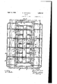
- Fig. 1 is a vertical sectional view of a casket mold and associated apparatus embod ing the principles of my invention
- Fpig. 2 a top plan View thereof. 7
- the apparatus. of Fig. 1 comprises a sections 2 and end portions 3, Fig. 2, which are joined at 'their flanged portions 4 by screw bolts 5 or in any other suitable manner to conan electrolytic solution.
- the inner dimensions of the mold are that of the outer dimensions of the article to be formed and the inlytic solution is to be formed is of the shape and conguration desired on the outer surfaceof the finished article.
- the mold is further provided with apertures or recesses 6 for receivinginserts7 which are made integral with the metal deposit o n the surface of the mold to constitute ear lugs for handle brackets or the like which are attached to the casket in a manner to be hereinafter stated.
- the base l of the casket is pro- 9 I vided with depressions 8 in spaced apart relation at the respective corners of the mold to produce excess metal for hand grips.
- the mold is provided with flanges 9 extending around its upper edges for receiving clamp-bolts 10 which secure a frame 11 there- 10 to.
- the frame portion 11 is provided with transverse supports 12 which project through a plurality of anodes13 to hold the latter in proper spaced relation in proximity with the inner surface of the mold.
- the anodes 13 may consist of solid metal formed in the man- .ner illustrated in Fig. 1 but are preferably perforated receptacles adapted to receive scrap metal 14 which is disposed adjacent to a perforatedwall 15 of lead or other suitable material.
- the perforated members are secured to a frame 16 of wood or other suitable material provided with openings 17 for receivingthe transverse supports 12 on which they are movably mounted.
- the anodes for convenience of handling and to permitmoving them in and out of the mold are made up in sections which are arranged and disposed in the mold in the manner shown in Fig. 2 in which a plurality of such baskets or anodes are disposed in parallel relation along the side walls of the mold and one or more anodes are disposed in proximity with the end walls of the mold, all of the anodes'being electrically connected by leads 18 to a conductor 19 constituting one leg of a source of electric currents.
- the perforated walls of the anodes adjacent thel side and end walls of the mold are shaped to correspond substantially to' the contour of the inner surface of the mold and as shown in Fig. 2, the lead wall sections 15 of the anodes are substantial.- ly abutting or may be so when the anodes are assembled in their working position.
- the Wood frame portion 16 of the anode baskets are provided with a chamfer 2O at their edge adjacent the corners of the walls 15 to provide access of the scrap metal and the electrolytic solution to the perforations in or near the extreme edge of the perforated Wall.
- the outer perforated walls of the anodes are provided with isolatingsections 21 of lead or other suitable material which cover up the perforations in the walls 15 adjacent the sharp projecting portions of the mold to obtain proper current density for the purpose of preventmg a direct action between the anodes and the projections of the mold.
- the inner edges ofthe upper portions of the mold wallfsections 2 and 3 A are adapted to receive a sealer frame 23 which is temporarily held in intimate contact with the mold sections byl clamping it between the frame lportion 11 and the flange 9 of the mold sections.
- a rubber liner 24 and a strip or liner 25 are secured to the mold or frame 11 as shown, and are adapted to project be ond the upper edge of the mold to provide a atle which prevents the deposition of metal on the portion of the sealer frame 23 with which the strip or liner is in contact.
- the mold is electrically connected by leads 26 to a source of electric current which constitutes the other leg of the line 19, one leg of which is connected to the anodes 13 by leads 18.
- the mold is not suspended in an electrolytic solution as commonly practiced in the making of articles by galvanoplastic process, but is preferably placed on or approximate to a separate vat or container 28 in which the electrolytic solution is stored and from which it is conducted to the -anodes 13 by a feed line 29 that connects to a pump 30 which is provided with outlet pipes 31 that project into the anodes.
- a return drain pipe 32 is provided which projects through the frame portion 11 on top of the mold which is the level at which the solution is maintained in the mold.
- pump 30 When current is applied to-the anodes and mold, pump 30 is actuated to maintain circulation of the electrolytic solution in the mold for the duration of the process of making electrolytic deposition on the inner surface of the mold. -'l ⁇ he process is continued until a deposit of desired thickness has been made on the surface of the mold and is then interrupted by disconnecting the electric circut from the current source.
- the mold is then dismembered by first laterally moving the anodes on their supports or supporting bars 12 to bring them together so that the lower extending portions of the anodes will clear the upper constructed portions of the.
- the sections 2 and 3 of the mold are dismembered and the finished casket which is a one-piece integral member is removed.
- the portions of the iinished article corresponding to and which were formed on the depressions 8 of the base of the mold are pressed inwardly in a suitable manner to provide depressions in the casket at the respective corners which constitute hand grips for handling the casket in its manufacture.
- the outer surface of the finished casket is the surface adjacent the mold, it will possess a smooth iinish when removed from the mold which eliminates buing and 7polishing operations which are necessary when the surface adjacent the anodes constitutes ⁇ the outer surface of articles made of galvanoplastic metal.
- anode member refers to either the perforated basket ⁇ lor baskets for anode material. or the solid blocks of anode material.
- transverse -members supported on said frame member and extending across said cathode, perforated anode containers supported on said transverse members and adjustable along said members transversely of the. cathode.
- the horizontal cross section area of said anode being larger in the lower portion than in the upper portion of the cathode thereby to facilitate current conductance through the a'lly adjustable sections.
- An apparatus for the electro-deposition of burial caskets comprising a liquid containing cathode shaped to substantially the contour of the casket to be deposited and an anode wider between portions of opposite wallsthan are the adjacent opposite walls of the cathode at a high elevation, 'said cathode being formed in a plurality of sections connected by liquid tight joints and said anode comprising a substantially insoluble perforated container for pieces of material to be electro deposited upon the side walls and bottom of the cathode.
Description
April, 12, 1932. G. ROSENQVIST GASKET Filed Aug.
INVENTOR Mud? Z 4M Patented Apr. 12, 1932 v UNITED STATES GUNNAR ROSENQVIST, OF PITTSBURGH, PENNSYLVANIA GASKET Application led August 1, 1928. Serial No. 296,839..
This invention relates to apparatus for making hollow articles of alvanoplastic material more particularly or the making of burial receptacles such as caskets orthe like.
The present application is-a continuation, in part, of an application lbearing Serial Number 220,945, filed September 21, 1927,
which discloses a method and apparatus for lmaking one-piece seamless caskets by electrolytic deposition.
The present invention has among its objects the provision of special apparatus for vmakin caskets or other hbllow articles by electro ytic deposition. A i
One object of the invention is to provide special forms and arrangements of anodes adapted for. cooperation with a mold for the making of casketsof desirable ornamental configuration and form.
In carrying out my invention, I utilize a metal mold comprising a plurality of sections which are arranged when joined to constitute an integral mold of the sha e and dimensions of the article to be forme In carrying out the process the mold is constituted a container or vat for an electrolytic solution which submerges the entire receiving surface of the m'old on which the deposition' is to be made as well as the anodes which are susended therein in a particular manner as will e hereinafter described.
In the making of hollow articles of irregu? lar shape and form by electrolytic deposition in accordance with methods heretofore practiced, it is difficult to maintain'an even current density. I have found that a substantially uniform current density conducive to j the formation of deposits of substantially uniform thickness is obtained by forming the anodes or the 'portion of the anodes adjacent the face or surface of the mold on which the deposit is to be made, complementary to th contour of the latter. I have also found that when the mold is made with sharp intersecting faces or pro? ,jections it is necessary to isolate the portion of the anodes adjacent thereto to obtain uniform current density which prevents the formation of excess metal at such portions. If such precautions are not taken, excess metal tional mold consisting of a base l, side porstitute a unitary mold capable of containing `ner surfaces of the mold on which the electro- .PATENT OFFICE will form on the projecting portions of the mold which builds up rapidly to contact with the anode resulting in a short circuit across the anode and mold.
One of the principal objects of the invention is the provision of inserts such as handle brackets and hinge lugs on the galvanoplastic metal and in accordance with the invention, such inserts are formed integrally with the deposited metal without the use of rivets, solder or Welding.
The invention further contemplates the provision of apparatus which is especially adapted for the making of hollow articles of relatively large sizes such as burial caskets in an expedient and eiicient manner whereby such articles may be produced in relatively large quantities in an economical manner.
1n the accompanying drawin s constituting a part hereof, and in which l1 e reference 70 characters designate like parts, Fig. 1 is a vertical sectional view of a casket mold and associated apparatus embod ing the principles of my invention, and Fpig. 2 a top plan View thereof. 7|
The apparatus. of Fig. 1 comprises a sections 2 and end portions 3, Fig. 2, which are joined at 'their flanged portions 4 by screw bolts 5 or in any other suitable manner to conan electrolytic solution. The inner dimensions of the mold are that of the outer dimensions of the article to be formed and the inlytic solution is to be formed is of the shape and conguration desired on the outer surfaceof the finished article.
The mold is further provided with apertures or recesses 6 for receivinginserts7 which are made integral with the metal deposit o n the surface of the mold to constitute ear lugs for handle brackets or the like which are attached to the casket in a manner to be hereinafter stated. The base l of the casket is pro- 9 I vided with depressions 8 in spaced apart relation at the respective corners of the mold to produce excess metal for hand grips. When the completed casket is removed from the mold, the deposits 8 are pressed upwardly to 1 project to the interior of the casket chamber thereby forming the handle grips. By so displacing the metal formed in the deposit 8 of the mold, it will be projecting inwardly in 5 the same manner as it projects downwardly after the molding operation.
The mold is provided with flanges 9 extending around its upper edges for receiving clamp-bolts 10 which secure a frame 11 there- 10 to. The frame portion 11 is provided with transverse supports 12 which project through a plurality of anodes13 to hold the latter in proper spaced relation in proximity with the inner surface of the mold. The anodes 13 may consist of solid metal formed in the man- .ner illustrated in Fig. 1 but are preferably perforated receptacles adapted to receive scrap metal 14 which is disposed adjacent to a perforatedwall 15 of lead or other suitable material. vThe perforated members are secured to a frame 16 of wood or other suitable material provided with openings 17 for receivingthe transverse supports 12 on which they are movably mounted.
The anodes for convenience of handling and to permitmoving them in and out of the mold, are made up in sections which are arranged and disposed in the mold in the manner shown in Fig. 2 in which a plurality of such baskets or anodes are disposed in parallel relation along the side walls of the mold and one or more anodes are disposed in proximity with the end walls of the mold, all of the anodes'being electrically connected by leads 18 to a conductor 19 constituting one leg of a source of electric currents.
As shown in Fig. 1 the perforated walls of the anodes adjacent thel side and end walls of the mold are shaped to correspond substantially to' the contour of the inner surface of the mold and as shown in Fig. 2, the lead wall sections 15 of the anodes are substantial.- ly abutting or may be so when the anodes are assembled in their working position. The Wood frame portion 16 of the anode baskets are provided with a chamfer 2O at their edge adjacent the corners of the walls 15 to provide access of the scrap metal and the electrolytic solution to the perforations in or near the extreme edge of the perforated Wall.
As shown in Fig. 1, the outer perforated walls of the anodes are provided with isolatingsections 21 of lead or other suitable material which cover up the perforations in the walls 15 adjacent the sharp projecting portions of the mold to obtain proper current density for the purpose of preventmg a direct action between the anodes and the projections of the mold.
The inner edges ofthe upper portions of the mold wallfsections 2 and 3 Aare adapted to receive a sealer frame 23 which is temporarily held in intimate contact with the mold sections byl clamping it between the frame lportion 11 and the flange 9 of the mold sections. A rubber liner 24 and a strip or liner 25 are secured to the mold or frame 11 as shown, and are adapted to project be ond the upper edge of the mold to provide a atle which prevents the deposition of metal on the portion of the sealer frame 23 with which the strip or liner is in contact. 'The mold is electrically connected by leads 26 to a source of electric current which constitutes the other leg of the line 19, one leg of which is connected to the anodes 13 by leads 18.
The mold is not suspended in an electrolytic solution as commonly practiced in the making of articles by galvanoplastic process, but is preferably placed on or approximate to a separate vat or container 28 in which the electrolytic solution is stored and from which it is conducted to the -anodes 13 by a feed line 29 that connects to a pump 30 which is provided with outlet pipes 31 that project into the anodes. A return drain pipe 32 is provided which projects through the frame portion 11 on top of the mold which is the level at which the solution is maintained in the mold.
When current is applied to-the anodes and mold, pump 30 is actuated to maintain circulation of the electrolytic solution in the mold for the duration of the process of making electrolytic deposition on the inner surface of the mold. -'l` he process is continued until a deposit of desired thickness has been made on the surface of the mold and is then interrupted by disconnecting the electric circut from the current source. The mold is then dismembered by first laterally moving the anodes on their supports or supporting bars 12 to bring them together so that the lower extending portions of the anodes will clear the upper constructed portions of the.
mold and all of the anodes are lifted out of the mold or the m'old may be lowered away from the anodes as desired. The sections 2 and 3 of the mold are dismembered and the finished casket which is a one-piece integral member is removed. The portions of the iinished article corresponding to and which were formed on the depressions 8 of the base of the mold are pressed inwardly in a suitable manner to provide depressions in the casket at the respective corners which constitute hand grips for handling the casket in its manufacture.
On account of the fact that the outer surface of the finished casket is the surface adjacent the mold, it will possess a smooth iinish when removed from the mold which eliminates buing and 7polishing operations which are necessary when the surface adjacent the anodes constitutes` the outer surface of articles made of galvanoplastic metal.
It is evident from the foregoing description of my invention that the apparatus for inaking hollow caskets as hereinbefore set forth, is simple and economical and adapted for the mental shapes and configurations.
Although the invention has been illustrated l'as embodied in the manufacture of burial re- A ceptacles, it will be obvious to those skilled in the art that it is' adapted for use generally where it is desired to form hollow articles in the manner stated and any article of galvanoplastic metal with inserts formed integrally therewith without departing from the principles herein set forth.
The term anode member as used in the claims, refers to either the perforated basket` lor baskets for anode material. or the solid blocks of anode material.
I claim: l. The combination with a liquid containing cathode of an expansible anode member supported entirely from outside the cathode con-l structed to deposite a substantially uniform thickness of metal on the cathode walls.
2. The combination with a liquid containing cathode undercut on the inside, of an expansible anode member, the expansible anode being constructed in a number of substantially rigid sections longitudinally of the cathode and separately removable therefrom.
3. The combination with a liquid containing cathode undercut on the inside and having a constricted portion above the undercut part, of an expansible and substantially inflexible anode, the dimensions of the anode across the lower portion expanded and in place adjacent the undercut part of the cathode being greater is than the inner corresponding dimension at the constricted part of the cathode.
4. The combination with a cathode` of an inflexible anode expansibleboth laterally and longitudinally of the cathode.
5. The combination with a liquid tight cathode adapted to receive a galvanoplastic deposit on the inner surface, and having a supporting flange around the top thereof, a frame member extending above said flange,
"transverse -members supported on said frame member and extending across said cathode, perforated anode containers supported on said transverse members and adjustable along said members transversely of the. cathode.
6. The combination with a liquid tight 'cathode adapted to receive a galvanoplastic deposit on the inner surface, of ainaterial extending around the top of the cathode and adapted to be free of deposit, a pair of spaced containers for pieces of anode metal within the cathode and supported from above the bottom of said material to be out of contact with the side and bottom cathode walls, said containers being perforated on at least the bottom and side portions adjacent the cathode walls.
7. The combination with a liquid tight cathode for galvanoplasticmetal, of a. plurality of perforate containers therein for j pieces of anode metal and means for supporting said containers from above the cathode and ermitting adjustment of each container longltudinally or transversely of tlie cathode.
8. The combination with a metal liquidcontaining galvanoplastic cathode, of ananode removably suspended therein from above "and out of contact with the cathode surfaces,
the horizontal cross section area of said anode being larger in the lower portion than in the upper portion of the cathode thereby to facilitate current conductance through the a'lly adjustable sections.
10. An apparatus for the electro-deposition of burial caskets comprising a liquid containing cathode shaped to substantially the contour of the casket to be deposited and an anode wider between portions of opposite wallsthan are the adjacent opposite walls of the cathode at a high elevation, 'said cathode being formed in a plurality of sections connected by liquid tight joints and said anode comprising a substantially insoluble perforated container for pieces of material to be electro deposited upon the side walls and bottom of the cathode.
11. The combination with a liquid tight cathode forming a receptacle for electrolyte and for receiving a deposit of galvanoplastic metal, of a plurality of perforate anode baskets separately supported within said cathode and each containing pieces of metal to be deposited, some of said baskets including therein an inner means for holding the pieces of metal therein of non-uniformdepthv and higher adjacent a cathode side of the anode baskets thanthroughout a portion of the bottom of the basket nearer the center of the receptacle.
12. The combination with a liquid tight cathode receptacle for electrolyte and for receiving a deposit of galvanoplastic metal, of a plurality of perforate anode baskets separately supported within said cathode receptacle and adapted for independent adjustbaskets being lled with pieces of anode metal to be deposited and at least those baskets intermediate the end baskets having therein means for holding the anode pieces 5 banked higher adjacent a cathode side of the basket than over some of the basket bottom.
14. The combination with a liquid tight elongated cathode receptacle for electrolyte and for receiving a deposit of galvanoplastic metal on the bottom `and side and end walls of a plurality of anode baskets separately supported from outside the cathode and arranged side by side in the receptacle throughout most of its length and adapted for adjustment toward and from each other and toward and from the receptacle end walls independently of eachother, said baskets being lled with pieces of anode metal to be deposited and there being such a number of baskets that when aligned lon itudinally Within the receptacle the end bas ets will be about the same distance from the receptacle end Walls that the longitudinal side walls of the receptacle are spaced from the baskets. In testimony whereof I have hereunto set my hand.
GUNNAR ROSENQVIST.
Priority Applications (1)
| Application Number | Priority Date | Filing Date | Title |
|---|---|---|---|
| US296839A US1853747A (en) | 1928-08-01 | 1928-08-01 | Casket |
Applications Claiming Priority (2)
| Application Number | Priority Date | Filing Date | Title |
|---|---|---|---|
| US296839A US1853747A (en) | 1928-08-01 | 1928-08-01 | Casket |
| GB2631928A GB322551A (en) | 1928-09-13 | 1928-09-13 | Improvements in apparatus for making caskets and like hollow articles by galvanoplastic process |
Publications (1)
| Publication Number | Publication Date |
|---|---|
| US1853747A true US1853747A (en) | 1932-04-12 |
Family
ID=26258192
Family Applications (1)
| Application Number | Title | Priority Date | Filing Date |
|---|---|---|---|
| US296839A Expired - Lifetime US1853747A (en) | 1928-08-01 | 1928-08-01 | Casket |
Country Status (1)
| Country | Link |
|---|---|
| US (1) | US1853747A (en) |
Cited By (2)
| Publication number | Priority date | Publication date | Assignee | Title |
|---|---|---|---|---|
| US10357417B1 (en) * | 2018-03-08 | 2019-07-23 | Raymond William Accolla | Rubber coating |
| US10813818B1 (en) * | 2018-03-08 | 2020-10-27 | Raymond William Accolla | Rubber coating |
-
1928
- 1928-08-01 US US296839A patent/US1853747A/en not_active Expired - Lifetime
Cited By (2)
| Publication number | Priority date | Publication date | Assignee | Title |
|---|---|---|---|---|
| US10357417B1 (en) * | 2018-03-08 | 2019-07-23 | Raymond William Accolla | Rubber coating |
| US10813818B1 (en) * | 2018-03-08 | 2020-10-27 | Raymond William Accolla | Rubber coating |
Similar Documents
| Publication | Publication Date | Title |
|---|---|---|
| US4933061A (en) | Electroplating tank | |
| US4127459A (en) | Method and apparatus for incremental electro-polishing | |
| DE3370660D1 (en) | A process of electroforming a metal product and electroformed metal product | |
| US1853747A (en) | Casket | |
| ES541142A0 (en) | A PROCEDURE FOR OBTAINING A METAL BY HALOGENIDE ELECTROLYSIS | |
| US1853700A (en) | Method of making caskets by galvanoplastic process | |
| FI81129C (en) | Anode and process for making the same | |
| US3708415A (en) | Rapid action electrolytic cell | |
| FR2449141A1 (en) | PROCESS FOR TRIMMING AND / OR POLISHING STEEL OBJECTS | |
| US1845052A (en) | Apparatus and process for making metal patterns | |
| GB322551A (en) | Improvements in apparatus for making caskets and like hollow articles by galvanoplastic process | |
| CN211161869U (en) | Forming die convenient to clutch for anode plate production | |
| US1931084A (en) | Mold for articles of galvanoplastic material | |
| US2421209A (en) | Electrolytic refining of metals | |
| US2217093A (en) | Skull separator | |
| USRE29874E (en) | Electroplating of the cut edges of sheet metal panels | |
| US3297559A (en) | Conductive mold rack for electrocleaning mold parts | |
| US485618A (en) | Apparatus for and process of refining copper by electricity | |
| US2148815A (en) | Concrete vault mold | |
| JPS60502258A (en) | Electrodes for electrometallurgical methods | |
| US2349662A (en) | Electroplating cell | |
| US1749275A (en) | Built-up shower bath | |
| FI85162C (en) | Electrolytic surface treatment system and method of application therein v for the manufacture of lock parts | |
| US1966102A (en) | Apparatus for the electrolytic treatment of liquids | |
| US2807065A (en) | Mold insert block |