US1853741A - Assichtobs to - Google Patents
Assichtobs to Download PDFInfo
- Publication number
- US1853741A US1853741A US1853741DA US1853741A US 1853741 A US1853741 A US 1853741A US 1853741D A US1853741D A US 1853741DA US 1853741 A US1853741 A US 1853741A
- Authority
- US
- United States
- Prior art keywords
- lever
- machine
- shaft
- printing
- ticket
- Prior art date
- Legal status (The legal status is an assumption and is not a legal conclusion. Google has not performed a legal analysis and makes no representation as to the accuracy of the status listed.)
- Expired - Lifetime
Links
- 241000282472 Canis lupus familiaris Species 0.000 description 20
- 239000004020 conductor Substances 0.000 description 17
- 210000003811 finger Anatomy 0.000 description 15
- 238000005192 partition Methods 0.000 description 6
- 230000000994 depressogenic effect Effects 0.000 description 4
- 210000003813 thumb Anatomy 0.000 description 4
- NJPPVKZQTLUDBO-UHFFFAOYSA-N novaluron Chemical compound C1=C(Cl)C(OC(F)(F)C(OC(F)(F)F)F)=CC=C1NC(=O)NC(=O)C1=C(F)C=CC=C1F NJPPVKZQTLUDBO-UHFFFAOYSA-N 0.000 description 3
- 230000000881 depressing effect Effects 0.000 description 2
- 241000063944 Odice Species 0.000 description 1
- 102100034742 Rotatin Human genes 0.000 description 1
- 101710200213 Rotatin Proteins 0.000 description 1
- SZKKRCSOSQAJDE-UHFFFAOYSA-N Schradan Chemical compound CN(C)P(=O)(N(C)C)OP(=O)(N(C)C)N(C)C SZKKRCSOSQAJDE-UHFFFAOYSA-N 0.000 description 1
- 239000012530 fluid Substances 0.000 description 1
- 150000002500 ions Chemical class 0.000 description 1
- 239000000463 material Substances 0.000 description 1
- 229910052751 metal Inorganic materials 0.000 description 1
- 239000002184 metal Substances 0.000 description 1
- 150000002739 metals Chemical class 0.000 description 1
- 229920000136 polysorbate Polymers 0.000 description 1
- 230000000717 retained effect Effects 0.000 description 1
Images


Classifications
-
- G—PHYSICS
- G07—CHECKING-DEVICES
- G07B—TICKET-ISSUING APPARATUS; FARE-REGISTERING APPARATUS; FRANKING APPARATUS
- G07B1/00—Machines for printing and issuing tickets
- G07B1/02—Machines for printing and issuing tickets employing selectable printing plates
-
- G—PHYSICS
- G07—CHECKING-DEVICES
- G07F—COIN-FREED OR LIKE APPARATUS
- G07F17/00—Coin-freed apparatus for hiring articles; Coin-freed facilities or services
- G07F17/42—Coin-freed apparatus for hiring articles; Coin-freed facilities or services for ticket printing or like apparatus, e.g. apparatus for dispensing of printed paper tickets or payment cards
Definitions
- This invention relates to' new and useful improvements in the 'machines shown and described in the patents of John F. Ohmer, 974,511 dated November 1 1910, 1,056,765 dated March 18, 1913, 1,1 ,655 dated September 12, 1916, 1,242,967 dated October 16, 1917, 1,274,192 dated July 30, 1918, 1,182,410 dated May 9, 1916, and the atents to John F. Ohmer and Harry J. ibley, 1,210,971 dated January 2, 1917, and 1,210,973 dated January 2, 1917. g
- This invention relates to new and useful improvements in machines for registering, recording and issuing tickets on railways,
- transportation tickets are printed andv forwarded to, the ticket oflices.
- These tickets contain the name'of the issuing station, the destination and other printed matter. If there were 999 stations, 997,002 different tickets would be required, in order to have one ticket from each station to each of the other stations. Since each station should have a quantity of tickets to each of the other stations, an immense number of tickets would be required. Assuming that each'station were provided with only 100 tickets to each of the other stations, the number of tickets required, would be 99,700,200. These tickets are'costly and require expensive filing equipment. Furthermore, each of these tickets must be dated by the ticket agent. The present arrangement is so cumbersome that it is utterly impracticable either to issue these tickets on the cars,
- the present invention relates to a machine that eliminates the necessity of rinting vast quantities of tickets and provi ing cumbersome filing equipment therefor.
- the machine issues the ticket showing the station where the passenger boards the car, the destination, the direction of travel, the amount he paid for the transportation, the serial number of the ticket, the date and an other information, such as instructions to t a passenger in regard to the ticket.
- the cost of printin and issuing the ticket is simply the 'cost of the paper which is an insigni cant item when compared with the cost of printing vast numbers of tickets as at resent.
- the ma.- chine prints the numbers of the stations instead ofthe names of the stations as is common railway ractice.
- the mechanism to print the num ersof stations from and to which the ticket is issued, the amount paid for the transportation, the classification of the'ticket andthe direction of travel are controlled by hand levers operated; by the conductor. However, at the time when the passengers are getting on the car, only a few of these levers need be touched by the conductor, for the station at which the car isand its direction of travel would "be set only .once. After the levers are set the conductor steps on a treadle or turns a crank and the ticket is issued in such a position that the passenger takes the ticket directly from the machine and passes into the car.
- the machine may be operated by other. means than the treadle or acrank, It may be actuated by an electric motor connected with the lighting circuit of the car, or it may be operated by the air-pressure service usually employed for applying brakes to the car.
- An suitable actuating means may be employe without departing from either the spirit of this invention or the scope of the claims.
- the time consumed in issuing the ticket is ver little indeed for the operation of the mac ine is very rapid, and the conductor can operate the machine as quickly as the passengers can board the car.
- Another object of the invention is to provide a detailed record which is printed almost simultaneously with the tickets and which detailed record shows the number of the machine, the stations from and to which the tickets were issued, the direction of travel, the amount paid for each ticket, the class of transportation, the serial number showing provide means whereby the'transaction of the conductor-may be readily audited and means are provided whereby when the conductor turns a key on starting his run, a record is printed showing the number of ticketsissued up to that time, the amount of fares heretofore paid for the tickets and the number of the machine. When his run has been completed he again turns the same key and a second record showing the same items is printed below the first record. The difierence between the figures o'n thesetwo impressions indicates the total numberof assengers carried between the time the two impres-.
- the ticket issued by the machine described in this application serves every purpose that the present form of tickets accomplish' while saving theexpense of printing the tickets, eliminating the need of a ticket ofice and providing a complete auditing systam.
- prac'ticeit is intended that the tickets shoul be taken by the passenger as soon as he pays his fare and retained by him until he eaves the car, when he surrenders the ticket to the conductor.
- the. assengers destination is printed on the t cketit is ossible for the passen er to ride further an his destination wit out paying. for the additional ride.
- ticket can be issued. Furthermore, means are rovided to, drive the ticket paper feed mec 'anism at a higher rate of s ed than the mechanism driving the detai ed record paper feed, thereby. economizing in the use of paper.
- a ortable machine has been constructed which willperform the function of issuing a ticket and making a recordthereof which ticket and record. would be in the form shown in this application and would comprise the printer, t e feeding and setting mechanism, printing Wheels and-actuators therefor, in combination with the date wheels andthe parts would function in the precise manner indicated in this ap lication.
- the portable machine would e 'minate the passenger and fare indicators and all other actuated indicators, as
- a portable machine has been constructed by simply eliminating' all of theunits and features shown in this application except those which are necessary'to erform the function of rinting and issuing the tickets and making a record thereof.
- the machine would not be too heavy to be carried by the conductor, as by strapping it over his shoulder, while 1 at the same time it could, of course, be mounted on a small pedestal in the car.
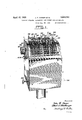
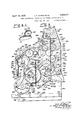
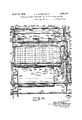
- Figure 1 is a rear view of the machine or the side fac ing the conductor.
- Figure 2 is a front view or the side are ing the passenger showings. ticket in position to be grasped by the passenger.
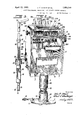
- Figure 3 is a detailed viewpartly in cross section showing the dash pot inthe supporting pedestal .of the machine.
- Figure 4 is a perspective view of the machine in an elevatedposition with the printing mechanism or unit omitt'edandthe casing removed.
- Figure 5 is a view, partlyin cross section
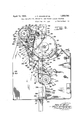
- Figure 6 is a side. elevational view of the left-hand side of the printer.
- Figure 6A is a detailed perspective view of the gearing to actuate the ticket paper feeding means.
- Figure 7 is a sectional view through the 130 machine showing the printing mechanism in position within the machine.
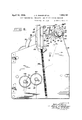
- I Figure 8 is an enlar ed view of the paper feed rollers-for the tickets. 7
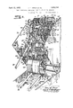
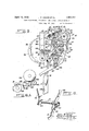
- Figure 9 is a sectional view taken immediately to the right of the left-hand side of the frame shown in Figure 4 and looking to the right.
- Figure is a perspective view'of the actuatin means for visible disks to indicate the num r of passengers carried on the trip.
- Figure 10A is a si e elevational view of the audible signal.
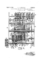
- Figure 11 is a cross sectional view taken on the inside of the right-hand side plate shown in' Figure 4, looking to the left and including the side vievt of the printing mechanism or unit in position.
- Figure 12 is an elevational view of the lefthand side of the machine, showing the printin unit in outline.
- igure 13 isa cross sectionalelevation of the reverse side of the structure shown in Fi rex9. I w
- igure 14 is a rear elevational view of the printing unit.
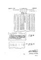
- Figure is a view of the printed detailed record.
- Fi re 16 is a view of one of the tickets issue by the machine
- y Figure 17 s a view of the record made by the total adder printing means and used in auditing the accounts.
- the machine is mounted on a floor late 1 provided with a suitable boss 2, whic receives the lower end of a supporting column 3, on which rests the bottomplate 4 of the machine.
- a suitable cover 5 is provided, inclosing the top, back and the two sides of the machine and extending over a portion of the back of the machine as shown in Figure 2.
- A'front cover 6 is hinged to the bottom plate 4 by means of hinges 7.
- the cover 5 is rovided with a flange 8 which extends over t e upper edge of the front cover 6 so that the front cover isheld in place when the cover is in position on the machine.
- the covers are provided with various apertures and slots which will be described with the related structure of the machine. The covers are,
- a of course made of a suitable material and so finished as to present a neat and attractive appearance.
- a coin tray 9 On top of the cover is provided a coin tray 9 so as to facilitate the collections of the fares.
- the machine is actuated from a treadle 10 mounted in lugs 11 which treadle extends through a slot 12 in the supporting column 3.
- the inner end of the treadle 10 is mounted on a pin 13 carried by the lower ends of two bars 14 which are attached to the lower.
- Bars 16 extend from the upperend of the dash pot 15, which bars are secured together at the upper end bymeans of a pin 17 on which pin is secured a bar 18 provlded at its-upper end with a beveled surface 19.
- Y A pin 20 extends through the supporting column 3 and res ceives a yoke 21 carried by the up r end of a rod 22, which rod carries on its l was end a piston 23 provided with a hole 24, which piston is slidable within the dash pot 15.
- the bars 16 are.
- the plate 29 is pivoted as at 30 to lugs 31 carried by the bottom plate 4.
- a second arm 32 ofthe plate 29 is rovided with a laterally extending lug 33, w ich lug is provided wit an u per beveled surface.
- the lug 33 engages a rack bar 34 slidable between rollers 35 mounted on pins carried by the left-hand frame wall 36 of the casing of the machine.
- the rackbar 34 is provided with teeth 37'which engage the teeth of a pinion 38 loosely mounted on the main drive shaft 39.
- the main drive shaft is provided with a gear 40 ( Figures 7 and 13). carrying a circular hub 41 which hub is providedwvith a notch 42 adapted to receive a finger 43 depending froma lever 44, fulcrumed at 45 to the side frame 36.
- the lever 44 is provided with a pin 46 serving as a fulcrum for a bell crank lever 47, which bell crank lever is normally pulled in a clockwise direction by means of a s ring 48.
- the lever 47 carries a finger 49 w ich finger normally lies in the path of movement of a pin 50 carried by the rack rod 34.
- the pinion 38 is not directly connected with the gear 40 nor with the main drive shaft 39.
- This connection is clearly shown in Figures 21 and 22 of application of Albert S. Wheelbarger, Serial Number 7 59,- 170 as is the full stroke mechanism 51 and the description of these parts need not be repeated in this ap lication. It is therefore apparent that eac time the treadle is depressed the rack rod 34 is raised so that the pin engages the finger-49 and raises the ever 44 against the tension of the spring 52, removing the finger 43 from the notch 42, so that the main drive shaft 39 can be rotated.
- the finger 49 after raising the lever 44 slides oil the pin 50, and the finger 43 therafter rides on the periphery of the hub 41.
- a suflicient number of teeth are provided on the pinion 38 so that one com lete rotation will be imparted to the she 39 each time the treadle is depressed, while on the return'movement of the rack rod 34 the shaft 39'is held against rotation by means of the lever 44 engaging the notch 42 in the.
- the upper end of the rack rod 34 is rovided with two s aced pins 58 and 59, ig ures 4, 9 and 13
- the sleeve 61 also carries a crank arm 63 which actuates a finger 64, which finger 'actuates a ratchet 65 secured to the units counter 66 of the counting mechanism showing the number of passengers carried on that trip.
- a pin 391' (Fig. 9) is carried by the partition wall 118 to prevent overthrow of the finger 64.
- a suitable pivoted pawl 67 is provided to prevent retrograde movement as the finger 64 moves downwardly by means of, the pin 58 engaging the arm 60 and lowering the finger 64 as the rack rod 34 moves on its reverse stroke.
- the arm 60 carries a pivoted dog 68 as shown in Fi ures 9 and 10. As the rack rod 34 is lowered, the dog 68 engages a ratchet 69, rigidly mounted on the shaft 62.
- the shaft 62 also carries a 10-toothed gear 70 ( Figure 4) which meshes with a 10-toothed gear on the units printing wheel 71, which is provided with printing numbers showing the total number of passengers carried.
- the gear 70 is provided with an annular flange 72 which is provided with a single tooth 73, which tooth 73 engages with one of the ten notches74 of the gear 7 5' carried by the tens printing wheel 75.
- each of the printing wheels 71, 75 77, and 79 are loosely mounted on the shaft 7 8 and that each of these wheels is provided with ten printing members from 0 to 9 inclusive. These printing wheels serve as a means, therefore, for counting the number of fares which have been collected, since the machine has been in operation. These wheels count up to 9,999, for thethousandths printing wheel is actuated by the hundredths gear 76 in like manner, as are the printing wheels 75 and 77. Obviously ,additional printing units could be provided if desired.
- Means are provided whereby the tens counter 80 ( Figures 2, 4 and 5) is actuated one notch or one-tenth of a revolution, when the units counter 66 has made a complete revolution and whereby the hundredths counter 81 is rotated for one-tenths of a revolution, when the tens counter 80 has completed a revolution.
- a disk 82 is secured to the hand lever'83.
- This disk 82 is provided with a triangular-shaped cam 84 and as the hand lever 83 is rotated from a vertical position, as shown in Figure 13, in a clockwise direction, the cam 84 engages a .lever 85, fulcrumed on a shaft86.
- the lever 85 carries a yoke 87, which oke is provided with two star wheels 88 and 89.
- the star wheel in mesh with the gear 90 secured to the counter 80, rotates the counter 80 for onetenth of a revolution as is fully described in the application of Wheelbarger 759,170.
- a lug 94 on the lever 86 engages a cam surface 95 of the lever 96 fulcrumed at 97 to the side frame 36 of the machine depressing the lever 96 against the tension of its sprin 97, secured to the lever and the side wall 36 and thereby actuatin or lowering the lug 98 forming a part 0 the lever 96 below the lug 99 carried by the toothed wheel 91.
- the lever 96 is raised by the spring 97 so that the lug 94 dro s into a notch 100 of the lever 96. This note holds the finger 92 on the lever 86 out of the notch 93 of the toothed wheel 91.
- the toothed wheel 91 therefore ma be now rotated in a clockwise direction.
- a 0g 101 prevents anti-clockwise rotation, which dog is pivoted on a in 102 on the side wall 36 of the machine an is pulled against the periphery of the toothed wheel by a spring 103.
- the lever '90 comletes its movement in a clockwise direction, its lower end 104 engages a pin 105 carried by a lever 106 pivoted ona pin 107.
- the lower end of the lever is thereby moved to the left as viewed in Figure 12 and to the right as viewed in Figure "7, was to overlie the upper end of the rack rod 34. It is therefore apparent that when the end of the run is reached and the direction lever 83 has been actuated by raising or lowering the same, the lever 106 locks the machine against operation.
- the counters 66, 80 and'81 In order to remove the lever 106 out of the path of movement of the rack rod 34it is necessary that the counters 66, 80 and'81 should be reset, which is accomplished by rotating the thumb wheel 114 on the shaft 115 in a clockwise direction. -As the toothed wheel 91 is thus rotated, the counters 66, 80 and 81 arereset by any well-known mechanism such'as that shown and described in the above mentioned application of Wheelbarger 759, 170,. and the lug 99, just before completing its revolution engages the lug 98 depressing the lever 96 so as to disengage the lug 94 to perm t the lever 90 to be pulled towards the toothed wheel 91 by means of the spring 107' ( Figure 13) secured to the lever 85 and.
- the disk 82 is pivoted on the shaft 109 and this disk is provided with teeth 110 which mesh with a pinion 111, which is fast on the shaft 78 ( Figure 5).
- a direction printing wheel 113 is also secured to the shaft 78 and on this printing wheel is suitable indicia such as N for north, S for south or any other suitable indicia.
- the counters 66, 80 and 81 are loosely mounted on the shaft, 115 but means are provided to hold these counters against rotation except when they are being reset by the thumb wheel 114 or while they are being actuated when a fare is being registered.
- This holding means consists of the star wheels 88 and 89, a dog 67 and three dogs 117 secured to the shaft-123.
- the do 67 is in the fori'gof a bel l crank lever pivote to a partition wall 118 and. tensioned' by means of a spring 119 secured to one end of the dog 67 and to the partition wall 118.
- This dog is clearly shown in Figure 9.
- the disk 82 is'provided with an arcuate cam 120, which, when the disk 82 is bein rotated to change the direction, enga es a ever 121 fulcrumed on the shaft 62 an provided at its upper end with a projection 122 adapted to engage the teeth of the gear attached to the counter 81. It would be, therefore, im ssible to turn the thumb wheel 114 unless t e direction had been completely changed.
- a cam 133 is secured to the shaft 115,'which cam is provided with acutaway portion ending in a shoulder 134.
- dog 135 is rigidl secured to the shaft 123'so as to move wit the dogs 117 which are also rigidly secured to the said shaft.
- -As'the shaft 115 isrotated clockwise as viewed in Figure 9 on the resetting operation the cam 133 moves the dog 135 to the left which is'the means of overcoming the tension of the spring125 and moves the dogs 117 so as to be in the path of movement of the pins 124.:1 This movement however does not take'place until after the ins 124 have passed beyondthe ends of the ogs 117.
- the lever 127 is rotatably mounted in the side frame 36 by means of a pin 128, which lever engages one of the dogs 117, as shown in Figures 4, 9 and 13.
- the sprin 52 operativel connects the lever 44 an lever 127.
- the ower end of the lever 127 rejects downwardly against the end of e full stroke mechanism 51 and the u per end of the lever 127 engages one of the ogs 117 rotatin the shaft 123 and pushin the upper end 0 the dogs into the path 0 movement of the pins 124.
- the full stroke mechanism 51 is raised, which raises the lower end of the lever 127 and removesthe upper end thereof from engagement with the dog, 117.
- the s ring 125 now pulls the dogs out of the ath o movement.
- the lever 127 also carries an arm 392 w ich enthe pinion 111, holdin2g it against rotatlon as long as the lev'erl is holding the do 117. y
- the disk 82 is also provided with a cam 129 ( Figure 9) which engages a pin '130'on the lever 106 which pulls the lever 106 when the disk 82 is being rotated so that the lower end thereof will lie in the path of movement of the rack rod 34.
- the cam 129 (Fig. 9) serves as an effective means to move the lever 106 to a position such as to lock the rack rod 34 against movement, but it must be remembered that after the gear 82 completes its. rotative movement the cam 129 is no longer in engagement with the pin 130.
- the disk 82 18 also provided with a cam 131 which enga' as a lever 132 tensioned by a spring 132. e object ,of the lever 132 is to provide holding meansto hold the disk 82 in position so that the disk will not rotate unless suflicient force is put upon the lever 83 to overcome the tension of the spring 133.
- the fare indicating drums 1'36, 137 and 138 indicate the cents, dimes, and dollars charged for the transportation of passengers and are loosely mounted on the shaft 115. Each of these drums is provided with numerals from zero to nine inclusive, to indicate the fare paid.
- the hand lever 139 which is the units lever is mounted on a sleeve 140 which sleeve is on the shaft 109, which sleeve carries a gear 141 which meshes with a pinion 142 loosely mounted on a shaft 143 supported by the side walls of the machine.
- the pinion 142 meshes with a pinion 144 loosel mounted on a shaft 145 supported by the si e wall 146 of the machine and the partition wall 118.
- the pinion 144 meshes with a pinion 147 secured to the units fare indicator 136.
- the lever 139 extends through the slot 148 in the casing 5 and adjacent to this slot are numerals one to nine inclusive.
- the conductor moves the hand lever 139 to a. position adjacent the pro r cents numeral and this movement rotates the disk 136 so that the proper cents numeral will appear in the opening 149 in the front of the casing.
- the tens lever 150 is secured to a sleeve 151 on the shaft 109 which sleeve carries a gear 152 which meshes with the pinion 153 loosely mounted on shaft 143, which pinion drives a gear 154 loosely mounted on the shaft 145, which gear drives a pinion 155 securedto the tens fare indicator drum 137.
- the dollar lever 156 is carried by a sleeve 157 on the shaft 109 which sleeve has secured thereto a ear 158 meshing with a pinion 159 carried y a collar 160 loosely mounted on the shaft 143, which-collar also carries a gear 161 which drives aar 162 loosely mounted on the shaft 145, w ich gear drives a' pinion 163 secured to the dollar drum 138.
- the sleeve 157 lies immediately adjacent the shaft 109 and surrounds the same while the sleeve 151 surrounds the sleeve 157 and the sleeve 140 is rotatably mounted on the sleeve 151.
- the sleeve 157 is an inner sleeve
- the sleeve 151 is an intermediate sleeve
- sleeve 140 is an outer sleeve as clearly shown in Figure 5.
- the dollars, dimes and cents levers are moved through slots in the casin 5 to indicate any fare from one cent to nine ollars ninety-nine cents and whatever fare is so indicated will appear behind the opening 149 in the casing so that it may be readily seen by the passengers.
- Means are also provided to show the class of the fares as, for instance, a ticket, one-half fare, commutation, school, coupon, mileage, transfer, pass, round trip, clergyman or any other class of fare which might-be in use on the tra ortation company.
- the class of fare is i z i icated behind the opening 149 by means of a drum 164, which drum is actuated by means of a lever 165 mounted on a sleeve 166 rotatably mounted on the sleeve 140, which sleeve 166 carries a gear 167 which drives a pinion 168 mounted on a sleeve 169 on the shaft 143, which sleeve carries a pinion 170 which drives a gear 171 which actuates a pinion 172 secured to the drum 164 which indicates the class of fares on the periphery thereof.
- Each of the gears 167, 141, 152 and 158 meshes with the pinions 173, 174, 175 and 176 respectively, (see Fig. 5) each of which pin- 'with gears 187,
- Thedate printing means is conventional and consistsof thumb wheels 181,182, and
- Thelevers 200 201 and 202slide thro h the, openings or sl0t s203 in the back of tfiecasing, Adjacentjto, these slots are numerals fromzero to. nine inclusive, which numerals indic e by Inumberlthe' station where the passenger boarded thetrain.
- the levers 200,; 20l-amd 202 are securedto sleeves 204, 205 and 206 respectively, which sleeve 204; is rotatably inounted on; the shaft 109, the sleeve 205 be ing, rotatably mounted on the sleeve 204 and th sl ev 206 b ng 0 a a 1y.-;.
- The. sleeves 204-, 205" and 206 1 spectively, :which 'gears. meshswith ;pinions 210,v 211. and .212 respectively which pinions are rigidly secured tofprintingrwheels 21,3, 2142M 2 re p t y,
- Thes s- 2 3 214 and 215 are provided with; printing typecom I sistingofnumerals from zero to -nine.,i nclnsive, ,The gears and pinions are, otlcourse, provided with a suitable numberof teeth so that the proper printing numerals will apar in place according to thepostion of the evers.
- the levers 216, 217,and: 218 likewise slide in slotsinthe casing and adjacent tothese slotsware numerals from zerofto nine vinclusive, to indicate, the number of the station which is the -,.dest-inaticn; oi the passenger.
- the sleeves 219 j and 220 are provided ,withsgears 221 and 222, respectivel while the level-218 is directly securedyto a .gear'223's
- the left-hand side plate 240 of the printer is provided with a pin 393.
- the pin 393- engages a stud 395 carried by the lower end of a ar 394 pivoted to the side wall 36 of the machine by means of a pin 396.
- the bar 394 is provided with a lug 397 adapted to engage a recess 398 in the rack bar 34.
- the bar 394 is provided with a spring 399 which spring tends to pull the lug 397 so that it will lie in the recess 398.
- the pin 393 When the printer is in position within the machine, the pin 393 holds the lug 397 out of the recess 398 but if the printer is removed, for any reason, the spring 399 actuates the bar 394 so that the lug 397 pro-- jects within the recess 398 and thereby locks the rack rod 34 so that it cannot be reciprocated. Since the rack rod 34 is the actuatingmeans for the machine it would follow that the entire machine is locked against operation unless the printer is fully inserted within the machine.
- stud arms 256 Projecting from the left-hand side late 240 'are stud arms 256 carrying a plate extending longitudinally of the printer.
- the right-hand side wall 241 supports a plurality of studs 258' which support a friction plate 259 spaced from the side wall 241. and normally pushed away from the side wall by means of springs 260.
- a removable rod 261 passes through the side walls 240 and 241, throu h the plate 257 and the friction plate 259 which rod supports a'roll of paper 262 which roll of paper .is 'frictionally held between the plates 257 and 259 by means of the 5 rings 260 which press the plate 259 against t e said roll.
- the roll 262 is the supply roll for the tickets which are to be printed.
- the first mentioned printing means includes a roller 263 revolvably mounted on the shaft 251.
- the shaft 251 supports duplicate arms 264 which arms are in the shape of a bell crank lever and are tensioned by'means of a spring 270 so as to beheld against adjusting studs 266, which springs are attached to the arms 264 and secured to the cross bar 266 secured to the side walls of the printer.
- a shaft 267 is rotatably mounted'in the arms 264 which shaft supports a platen 268.
- Bell crank levers 269 are pivoted on the shaft 267 5 and between the arms 264 lying immediately adjacent to said arms.
- the s ring 265 is connected with the upper end 0 each of the bell crank levers 269 and to the cross bar 266.
- the lower end of the bell crank lever supports a rotary ink pad 271.
- a roller 272 is mounted on a shaft 273 which may be slip ed into slots 274 ( Figure 6) of the printer.
- a shaft 281 is rotatably mounted in the side walls of the rinter, which shaft is provided with a printing segment 282 such as an electrotype, containing the rules of the company or statement that the tickets are a receipt for the fares paid or any other descriptive matter desired.
- a cam 283 is also carried by the shaft 281 which shaft is rotated by means hereinafter to be described.
- a gear 286 is rigidly secured to the collar 285 rotatably mounted on the stub shaft 284, and a chambered disk 287 is rigidly secured to thegear 286, which disk is provided with a circular orifice 288 and a slot 289 extending through the disk 287.
- One of the pins 290 supporting one of the rollers 35 is rovided with an inwardly extended projection having its upper and lower surfaces parallel. This pro ection or lug passes through the slot 289 when the printing mechanism is being inserted into the frame of the machine and thereafter passes into the orifice 288.
- the disk 287 is provided with a notch 291 adapted to receive 9.
- lug 292 extending upwardly from a lever 293 pivoted on a in 294 on the side wall 240 of the printer. is lever is normally pulled upwardly by means of a spring 295 attached to the lever and to the side wall 240 of the printer.
- the inner end of the lever is provided with a beveled surface 296.
- the beveled surface 296 engages a pin 297 ( Figure 4) which pin depresses the lever and removes the lug 292 from the notch-291.
- the function of the lever 293 is to position the notch 289 relatively to the lug 290, for if the lug 290 were not in ali ment with the notch 289 it would be impossible to insert fully the rinter within the frame of the machine. I urthermore, the lever insures the parts being in the exact position in which they should be so that the second printing operation, hereinafter to be described, will be impressed on the ticket exactly where it should be relative to the
Landscapes
- Physics & Mathematics (AREA)
- General Physics & Mathematics (AREA)
- Devices For Checking Fares Or Tickets At Control Points (AREA)
Description
April 1-2, 1932. J. F. 'OHMER ET AL 1,353,741
FARE REGISTERING, RECORDING, AND TICKET ISSUING MACHINE? Filed Aug; 28, 1925 12 Sheets-Sheet 1 awe/Mons April 12, 1932. J. F. OHMER ET AL FARE REGISTERING, RECORDING, AND IICJKE'I ISSUING MACHINE Filed Aug. 28. 1925 12 Sheets-Sheet 5 [N VENTORS Jofin 0511121 B V 0/62?! 717/?ee/6ar er A TTOR/VE Y April 9 J. F. OHMER ET AL 1,353,741
FARE REGISTERING, RECORDING, AND TICKET ISSUING MACHINE Filed Aug 28, 1925 12 Sheets-Sheet 6 INVENTO R V 827/31: Cf @2152. By "'f n? f A TTORN; Y
April 12, 1932- J. F. OHMER ET AL FARE REGISTERING, RECORDING, AND TICKET ISSUING MACHINE 1925 12 Sheets-Sheet '7 Filed Aug. 28
5 W M n m MZ ErM m X MW w. JM r 3mm 0 April 12, 1932. .1. F. OHMER ET AL 1,853,741
RECORDING AND TICKET ISSUING MACHINE FARE REGISTERING,
Filed Aug. 28,
1925 12 Sheets-Sheet 8 11v VENTORIS J05" mm April 12, 1932 J. F. OHMER ET AL FARE REGISTERING, RECORDING, AND TICKET ISSUING MACHINE 1'2 Sheets-Sheet Filed Aug. 28, 1925 Y [/VVENTORS 71 $1 5 HY If? l 6 ATTORAEY April 12, 1932. J. F. OHMER ET AL FARE REGISTERING, RECORDING, AND TICKET ISSUING MACHINE 12 Sheets-Sheet 10 Filed Aug. 28,
1N VNroles a Z M M W. 0.
,4 TTORNEJ" Patented Apr. 12, 1932 um'rao STATES. PATENT OFFICE JOHN F. CHEER AND ALBERT B. WHEELBABGER, OF DAYTON, OHIO, ASSIGNOBS TO OHMEB FARE REGISTER COMPANY, 01 DAYTON, OHIO, A COBIPOBATIONOF OHIO FARE REGISTERING, RECORDING, AItTD TICKET ISBUING MACHINE Application fled August as, 1925. Serial no, 53,082.
This invention relates to' new and useful improvements in the 'machines shown and described in the patents of John F. Ohmer, 974,511 dated November 1 1910, 1,056,765 dated March 18, 1913, 1,1 ,655 dated September 12, 1916, 1,242,967 dated October 16, 1917, 1,274,192 dated July 30, 1918, 1,182,410 dated May 9, 1916, and the atents to John F. Ohmer and Harry J. ibley, 1,210,971 dated January 2, 1917, and 1,210,973 dated January 2, 1917. g
This invention relates to new and useful improvements in machines for registering, recording and issuing tickets on railways,
.. street cars,'and busses and is designed to take the lace of the usual cumbersome, spacious tic et racks common to ticket'ofiices. The machines may be placed on the'cars and tickets printed and issued by the conductor, thereby eliminating the necessity of a ticket agent. v 1
At the present time transportation tickets are printed andv forwarded to, the ticket oflices. These tickets contain the name'of the issuing station, the destination and other printed matter. If there were 999 stations, 997,002 different tickets would be required, in order to have one ticket from each station to each of the other stations. Since each station should have a quantity of tickets to each of the other stations, an immense number of tickets would be required. Assuming that each'station were provided with only 100 tickets to each of the other stations, the number of tickets required, would be 99,700,200. These tickets are'costly and require expensive filing equipment. Furthermore, each of these tickets must be dated by the ticket agent. The present arrangement is so cumbersome that it is utterly impracticable either to issue these tickets on the cars,
or to dispense'with the ticket agent.
The present invention relates to a machine that eliminates the necessity of rinting vast quantities of tickets and provi ing cumbersome filing equipment therefor. The machine issues the ticket showing the station where the passenger boards the car, the destination, the direction of travel, the amount he paid for the transportation, the serial number of the ticket, the date and an other information, such as instructions to t a passenger in regard to the ticket. The cost of printin and issuing the ticket, by means of the ma iine described in this application, is simply the 'cost of the paper which is an insigni cant item when compared with the cost of printing vast numbers of tickets as at resent.
n the contruction shown herein, the ma.- chine prints the numbers of the stations instead ofthe names of the stations as is common railway ractice. The mechanism to print the num ersof stations from and to which the ticket is issued, the amount paid for the transportation, the classification of the'ticket andthe direction of travel are controlled by hand levers operated; by the conductor. However, at the time when the passengers are getting on the car, only a few of these levers need be touched by the conductor, for the station at which the car isand its direction of travel would "be set only .once. After the levers are set the conductor steps on a treadle or turns a crank and the ticket is issued in such a position that the passenger takes the ticket directly from the machine and passes into the car. Obviously, the machine may be operated by other. means than the treadle or acrank, It may be actuated by an electric motor connected with the lighting circuit of the car, or it may be operated by the air-pressure service usually employed for applying brakes to the car. An suitable actuating means may be employe without departing from either the spirit of this invention or the scope of the claims. The time consumed in issuing the ticket is ver little indeed for the operation of the mac ine is very rapid, and the conductor can operate the machine as quickly as the passengers can board the car.
Another object of the invention is to provide a detailed record which is printed almost simultaneously with the tickets and which detailed record shows the number of the machine, the stations from and to which the tickets were issued, the direction of travel, the amount paid for each ticket, the class of transportation, the serial number showing provide means whereby the'transaction of the conductor-may be readily audited and means are provided whereby when the conductor turns a key on starting his run,a record is printed showing the number of ticketsissued up to that time, the amount of fares heretofore paid for the tickets and the number of the machine. When his run has been completed he again turns the same key and a second record showing the same items is printed below the first record. The difierence between the figures o'n thesetwo impressions indicates the total numberof assengers carried between the time the two impres-.
sions were made and the total amount. received from these passengers. The only auditing therefore, that'is re uired consists.
of two-simple substractions an nothing else. This is rendered possible 1) the use of the total auditing mechanism-s own .in the ap- Elications of Albert, S.Wheelbarger, Serial umbe'r- 7 59 170, filedDecemberBl, 1924, and 2s 52- filedhlay 7, 1925. j invention is particularly applicabl-eto interurban railways and busses, where frequent stops are uired. It is impracticable to provide a tie at odice at each-of these :2? and the fares are usually collected in The ticket issued by the machine described in this application serves every purpose that the present form of tickets accomplish' while saving theexpense of printing the tickets, eliminating the need of a ticket ofice and providing a complete auditing systam. In prac'ticeit is intended that the tickets shoul be taken by the passenger as soon as he pays his fare and retained by him until he eaves the car, when he surrenders the ticket to the conductor. Inasmuch as the. assengers destination is printed on the t cketit is ossible for the passen er to ride further an his destination wit out paying. for the additional ride. If the superintendent of the transportation company'suspects' that one of the conductors is dishonest and is reselling the tickets to passengers on runs subsequent tothe one on which the ticket was is sued, an inspector could board a. carat any place and look over or inspectthe tickets held y the passengers. In case any-passenger held a ticket not issued on that run, it would be B1proof conclusive that the conductor-was di onest. A ready means is therefore, afforded for eliminating any dishonest practice by-the conductor.
This invention provides many other improvements, such as printin two operations so that the in used in printthe ticket by.
"ticket can be issued. Furthermore, means are rovided to, drive the ticket paper feed mec 'anism at a higher rate of s ed than the mechanism driving the detai ed record paper feed, thereby. economizing in the use of paper.
- he machine is so constructed that one or more units thereof may be omitted to suit the varying needs of the transportation company. As a matter of fact, a ortable machine has been constructed which willperform the function of issuing a ticket and making a recordthereof which ticket and record. would be in the form shown in this application and would comprise the printer, t e feeding and setting mechanism, printing Wheels and-actuators therefor, in combination with the date wheels andthe parts would function in the precise manner indicated in this ap lication. The portable machine would e 'minate the passenger and fare indicators and all other actuated indicators, as
well as the totalizer, the totalizing printing mechanism and the pedestal foot operating mechanism. In other words a portable machine has been constructed by simply eliminating' all of theunits and features shown in this application except those which are necessary'to erform the function of rinting and issuing the tickets and making a record thereof. By constructing such a machine of-light metals, the machine would not be too heavy to be carried by the conductor, as by strapping it over his shoulder, while 1 at the same time it could, of course, be mounted on a small pedestal in the car.
In the accompanying drawings Figure 1 is a rear view of the machine or the side fac ing the conductor.
Figure 2 is a front view or the side are ing the passenger showings. ticket in position to be grasped by the passenger.
Figure 3 is a detailed viewpartly in cross section showing the dash pot inthe supporting pedestal .of the machine.
Figure 4 is a perspective view of the machine in an elevatedposition with the printing mechanism or unit omitt'edandthe casing removed.
Figure 5, is a view, partlyin cross section,
of the shafts connected by the line y-y of Figure 11 and showing the parts mounted thereon. Figure 6 is a side. elevational view of the left-hand side of the printer. Figure 6A is a detailed perspective view of the gearing to actuate the ticket paper feeding means.
Figure 7 is a sectional view through the 130 machine showing the printing mechanism in position within the machine. I Figure 8 is an enlar ed view of the paper feed rollers-for the tickets. 7
Figure 9 is a sectional view taken immediately to the right of the left-hand side of the frame shown in Figure 4 and looking to the right.
Figure is a perspective view'of the actuatin means for visible disks to indicate the num r of passengers carried on the trip. Figure 10A is a si e elevational view of the audible signal.
Figure 11 is a cross sectional view taken on the inside of the right-hand side plate shown in'Figure 4, looking to the left and including the side vievt of the printing mechanism or unit in position.
Figure 12 is an elevational view of the lefthand side of the machine, showing the printin unit in outline.
Figure is a view of the printed detailed record.
Fi re 16 is a view of one of the tickets issue by the machine, and y Figure 17s a view of the record made by the total adder printing means and used in auditing the accounts.
Throughout the specification and drawings, similar reference characters indicate corresponding parts.
Referring more particularly to the drawings the machine is mounted on a floor late 1 provided with a suitable boss 2, whic receives the lower end of a supporting column 3, on which rests the bottomplate 4 of the machine.
A suitable cover 5 is provided, inclosing the top, back and the two sides of the machine and extending over a portion of the back of the machine as shown in Figure 2. A'front cover 6 is hinged to the bottom plate 4 by means of hinges 7. The cover 5 is rovided with a flange 8 which extends over t e upper edge of the front cover 6 so that the front cover isheld in place when the cover is in position on the machine. The covers are provided with various apertures and slots which will be described with the related structure of the machine. The covers are,
a of course, made of a suitable material and so finished as to present a neat and attractive appearance. On top of the cover is provided a coin tray 9 so as to facilitate the collections of the fares.
The machine is actuated from a treadle 10 mounted in lugs 11 which treadle extends through a slot 12 in the supporting column 3. The inner end of the treadle 10 is mounted on a pin 13 carried by the lower ends of two bars 14 which are attached to the lower.
end of a dash pot 15, which dash pot is closed at both ends as shown in Figure 3. Bars 16 extend from the upperend of the dash pot 15, which bars are secured together at the upper end bymeans of a pin 17 on which pin is secured a bar 18 provlded at its-upper end with a beveled surface 19. Y A pin 20 extends through the supporting column 3 and res ceives a yoke 21 carried by the up r end of a rod 22, which rod carries on its l wer end a piston 23 provided with a hole 24, which piston is slidable within the dash pot 15. The bars 16 are. provided with pins 25, to which are attached springs 26, which are secured at their other ends in the lower part 3; the supporting column 3 by means-of pins Fach time the treadle is depressed by the- .eration. When the operators foot is removed from the tread1e'10 the springs 26 pull the dash pot downwardly relative. to the piston 23 and the fluid moves in the reverse direction from that heretofore described.
The beveled surface. 19of the bar 18 engages an arm 28 of a plate 29. The plate 29 is pivoted as at 30 to lugs 31 carried by the bottom plate 4. A second arm 32 ofthe plate 29 is rovided with a laterally extending lug 33, w ich lug is provided wit an u per beveled surface. Each time. the tread e, therefore, is depressed the plate 29 is raised on its pivot 30.
The lug 33 engages a rack bar 34 slidable between rollers 35 mounted on pins carried by the left-hand frame wall 36 of the casing of the machine. The rackbar 34 is provided with teeth 37'which engage the teeth of a pinion 38 loosely mounted on the main drive shaft 39. .The main drive shaft is provided with a gear 40 (Figures 7 and 13). carrying a circular hub 41 which hub is providedwvith a notch 42 adapted to receive a finger 43 depending froma lever 44, fulcrumed at 45 to the side frame 36. "The lever 44 is provided with a pin 46 serving as a fulcrum for a bell crank lever 47, which bell crank lever is normally pulled in a clockwise direction by means of a s ring 48. The lever 47 carries a finger 49 w ich finger normally lies in the path of movement of a pin 50 carried by the rack rod 34. The pinion 38 is not directly connected with the gear 40 nor with the main drive shaft 39. This connection is clearly shown in Figures 21 and 22 of application of Albert S. Wheelbarger, Serial Number 7 59,- 170 as is the full stroke mechanism 51 and the description of these parts need not be repeated in this ap lication. It is therefore apparent that eac time the treadle is depressed the rack rod 34 is raised so that the pin engages the finger-49 and raises the ever 44 against the tension of the spring 52, removing the finger 43 from the notch 42, so that the main drive shaft 39 can be rotated. The finger 49 after raising the lever 44 slides oil the pin 50, and the finger 43 therafter rides on the periphery of the hub 41. A suflicient number of teeth are provided on the pinion 38 so that one com lete rotation will be imparted to the she 39 each time the treadle is depressed, while on the return'movement of the rack rod 34 the shaft 39'is held against rotation by means of the lever 44 engaging the notch 42 in the.
' At the other end of the shaft 39 is a flan d disk 53 (Fi re 11) which cooperates wit a lever 54. li a ch. conductor is provided with an identifying key 477 (Figure 1) which raises the finger 55 of the lever 54 from a single notch 56 in the disk 53 as is clearly shown and described in the said copending application of Wheelbar r 7 59,170. The machine is therefore locke against operation until the conductors key is inserted and the key must be full inserted so that the'printed number, whic is the conductors number,
carried on the end of the key must be in printing position.
The upper end of the rack rod 34 is rovided with two s aced pins 58 and 59, ig ures 4, 9 and 13 As the'pin 59 is raised with the rack rod 34 it enga es an arm 60 mounted on a sleeve 61, whic sleeve is rotatably mounted on the shaft 62. The sleeve 61 also carries a crank arm 63 which actuates a finger 64, which finger 'actuates a ratchet 65 secured to the units counter 66 of the counting mechanism showing the number of passengers carried on that trip. A pin 391' (Fig. 9) is carried by the partition wall 118 to prevent overthrow of the finger 64. A suitable pivoted pawl 67 is provided to prevent retrograde movement as the finger 64 moves downwardly by means of, the pin 58 engaging the arm 60 and lowering the finger 64 as the rack rod 34 moves on its reverse stroke.
The arm 60 carries a pivoted dog 68 as shown in Fi ures 9 and 10. As the rack rod 34 is lowered, the dog 68 engages a ratchet 69, rigidly mounted on the shaft 62. The shaft 62 also carries a 10-toothed gear 70 (Figure 4) which meshes with a 10-toothed gear on the units printing wheel 71, which is provided with printing numbers showing the total number of passengers carried. The gear 70 is provided with an annular flange 72 which is provided with a single tooth 73, which tooth 73 engages with one of the ten notches74 of the gear 7 5' carried by the tens printing wheel 75. It will therefore be obvious t at the gear 70 is rotated one notch each time a fare is registered and the gear 70 will rotate the prmting wheel 71 one notch, or from the printing number reviously in position to the next succeeding number. )Vhen the gear 70 has made a complete revolution, the'tooth 73 engages one of the notches 74 on the tens printing gear 75 and rotates the tens printing wheel one notch or one-tenth of a revolution, which likewise rotates the tens gear 7 6 one-tenth of a revolution. The hundredths printing wheel 77 is actuated in like manner. It will be understood that each of the printing wheels 71, 75 77, and 79 are loosely mounted on the shaft 7 8 and that each of these wheels is provided with ten printing members from 0 to 9 inclusive. These printing wheels serve as a means, therefore, for counting the number of fares which have been collected, since the machine has been in operation. These wheels count up to 9,999, for thethousandths printing wheel is actuated by the hundredths gear 76 in like manner, as are the printing wheels 75 and 77. Obviously ,additional printing units could be provided if desired.
Means are provided whereby the tens counter 80 (Figures 2, 4 and 5) is actuated one notch or one-tenth of a revolution, when the units counter 66 has made a complete revolution and whereby the hundredths counter 81 is rotated for one-tenths of a revolution, when the tens counter 80 has completed a revolution. Referring to Figures 4, 9 and 13 it will be noted that a disk 82 is secured to the hand lever'83. This disk 82 is provided with a triangular-shaped cam 84 and as the hand lever 83 is rotated from a vertical position, as shown in Figure 13, in a clockwise direction, the cam 84 engages a .lever 85, fulcrumed on a shaft86. The lever 85 carries a yoke 87, which oke is provided with two star wheels 88 and 89. As the units counter 66 makes a complete rotation, the star wheel in mesh with the gear 90 secured to the counter 80, rotates the counter 80 for onetenth of a revolution as is fully described in the application of Wheelbarger 759,170.
When the end of the run is reached the conduct-or moves the hand lever 83 into its upper ment rotates the lever 86* (Figure 12) secured to the shaft 86 away from the toothed wheel 91 so that the finger 92 of the lever 86* is withdrawn from the notch 93 of the toothed wheel 91 .or in a clockwise direction. A lug 94 on the lever 86 engages a cam surface 95 of the lever 96 fulcrumed at 97 to the side frame 36 of the machine depressing the lever 96 against the tension of its sprin 97, secured to the lever and the side wall 36 and thereby actuatin or lowering the lug 98 forming a part 0 the lever 96 below the lug 99 carried by the toothed wheel 91. As soon as the lug 94 passes beyond the cam surface 95, the lever 96 is raised by the spring 97 so that the lug 94 dro s into a notch 100 of the lever 96. This note holds the finger 92 on the lever 86 out of the notch 93 of the toothed wheel 91. The toothed wheel 91 therefore ma be now rotated in a clockwise direction. A 0g 101 prevents anti-clockwise rotation, which dog is pivoted on a in 102 on the side wall 36 of the machine an is pulled against the periphery of the toothed wheel by a spring 103. Just before the lever '90 comletes its movement in a clockwise direction, its lower end 104 engages a pin 105 carried by a lever 106 pivoted ona pin 107. The lower end of the lever is thereby moved to the left as viewed in Figure 12 and to the right as viewed in Figure "7, was to overlie the upper end of the rack rod 34. It is therefore apparent that when the end of the run is reached and the direction lever 83 has been actuated by raising or lowering the same, the lever 106 locks the machine against operation.
In order to remove the lever 106 out of the path of movement of the rack rod 34it is necessary that the counters 66, 80 and'81 should be reset, which is accomplished by rotating the thumb wheel 114 on the shaft 115 in a clockwise direction. -As the toothed wheel 91 is thus rotated, the counters 66, 80 and 81 arereset by any well-known mechanism such'as that shown and described in the above mentioned application of Wheelbarger 759, 170,. and the lug 99, just before completing its revolution engages the lug 98 depressing the lever 96 so as to disengage the lug 94 to perm t the lever 90 to be pulled towards the toothed wheel 91 by means of the spring 107' (Figure 13) secured to the lever 85 and.
to a sleeve 414 on the shaft78. The lever 106 is now retracted from the path of movement of rack rod 34 by means of a spring 108 secured to. said lever and to one of the side walls of the machine.
The disk 82 is pivoted on the shaft 109 and this disk is provided with teeth 110 which mesh with a pinion 111, which is fast on the shaft 78 (Figure 5). A direction printing wheel 113 is also secured to the shaft 78 and on this printing wheel is suitable indicia such as N for north, S for south or any other suitable indicia. The counters 66, 80 and 81 are loosely mounted on the shaft, 115 but means are provided to hold these counters against rotation except when they are being reset by the thumb wheel 114 or while they are being actuated when a fare is being registered. This holding means consists of the star wheels 88 and 89, a dog 67 and three dogs 117 secured to the shaft-123. The do 67 is in the fori'gof a bel l crank lever pivote to a partition wall 118 and. tensioned' by means of a spring 119 secured to one end of the dog 67 and to the partition wall 118. This dog is clearly shown in Figure 9.
By referring to Figures 4 and 13, it is seen that the disk 82 is'provided with an arcuate cam 120, which, when the disk 82 is bein rotated to change the direction, enga es a ever 121 fulcrumed on the shaft 62 an provided at its upper end with a projection 122 adapted to engage the teeth of the gear attached to the counter 81. It would be, therefore, im ssible to turn the thumb wheel 114 unless t e direction had been completely changed. As soon as the direction lever 83 has been moved its full distance the cam 120 asses beyond the lever 121 so that 'the con uctor can rotate the counters 66, 80 and 81 back to zero; As the counters approach the zero oint, the three dogs 117 secured to the sha 123 rotatably mounted in the side wall 36 and the partition wall 118 move inwardly towards the counters 66, 80 and 81 engaging pins 124 carried by the said counters and stopping each of the counters at zero. As long as the dogs are in engagement with the pins 124 the counters are prevented from rotating further l are normally pulled away from the counters by means of a spring 125 (Fi 9) secured to a pin 126 on the side wall 36 o the machine.
A cam 133 is secured to the shaft 115,'which cam is provided with acutaway portion ending in a shoulder 134. dog 135 is rigidl secured to the shaft 123'so as to move wit the dogs 117 which are also rigidly secured to the said shaft. -As'the shaft 115 isrotated clockwise as viewed in Figure 9 on the resetting operation the cam 133 moves the dog 135 to the left which is'the means of overcoming the tension of the spring125 and moves the dogs 117 so as to be in the path of movement of the pins 124.:1 This movement however does not take'place until after the ins 124 have passed beyondthe ends of the ogs 117. The instant the counters are reset, the shoulder 134 passes beyond the dog 135 and the spring 125 pullsthe dog into the cutaway portion of the cam. The dog 135 (finger'92 and pawl 67) now'hold the shaft 115 against movement in any direction. The conductor, therefore, cannot reset the counters 60, 80 and 81 beyond the zero point nor can he reset the counters twice in succession and it is necemary for him to completely reset the counters before he can operate the machine, as heretofore described. The lever 127 is rotatably mounted in the side frame 36 by means of a pin 128, which lever engages one of the dogs 117, as shown in Figures 4, 9 and 13. The sprin 52 operativel connects the lever 44 an lever 127. The ower end of the lever 127 rejects downwardly against the end of e full stroke mechanism 51 and the u per end of the lever 127 engages one of the ogs 117 rotatin the shaft 123 and pushin the upper end 0 the dogs into the path 0 movement of the pins 124. However, when the counters 66, 80 and 81 have been reset and upon actuation of the rack rod 34, the full stroke mechanism 51 is raised, which raises the lower end of the lever 127 and removesthe upper end thereof from engagement with the dog, 117. The s ring 125 now pulls the dogs out of the ath o movement. of the pins 124 so that the o thereafter present no interference to t e proper actuation of the counters to count the number of passen rs for that tri The lever 127 also carries an arm 392 w ich enthe pinion 111, holdin2g it against rotatlon as long as the lev'erl is holding the do 117. y
The disk 82 is also provided with a cam 129 (Figure 9) which engages a pin '130'on the lever 106 which pulls the lever 106 when the disk 82 is being rotated so that the lower end thereof will lie in the path of movement of the rack rod 34. The cam 129 (Fig. 9) serves as an effective means to move the lever 106 to a position such as to lock the rack rod 34 against movement, but it must be remembered that after the gear 82 completes its. rotative movement the cam 129 is no longer in engagement with the pin 130. a It is at this time that it is necessary for the lower end 104 of the lever to engage the pin 105 so as to hold the lever-106 in looking engagement with the rack rod 34 when the cam 129 has moved be yond the pin 130. It is therefore, impossible to re r passengers unless the direction indicatmg lever is completely up or completely down. The disk 82 18 also provided with a cam 131 which enga' as a lever 132 tensioned by a spring 132. e object ,of the lever 132 is to provide holding meansto hold the disk 82 in position so that the disk will not rotate unless suflicient force is put upon the lever 83 to overcome the tension of the spring 133.
The fare indicating drums 1'36, 137 and 138 indicate the cents, dimes, and dollars charged for the transportation of passengers and are loosely mounted on the shaft 115. Each of these drums is provided with numerals from zero to nine inclusive, to indicate the fare paid. The hand lever 139 which is the units lever is mounted on a sleeve 140 which sleeve is on the shaft 109, which sleeve carries a gear 141 which meshes with a pinion 142 loosely mounted on a shaft 143 supported by the side walls of the machine. The pinion 142 meshes with a pinion 144 loosel mounted on a shaft 145 supported by the si e wall 146 of the machine and the partition wall 118. The pinion 144 meshes with a pinion 147 secured to the units fare indicator 136. The lever 139 extends through the slot 148 in the casing 5 and adjacent to this slot are numerals one to nine inclusive. The conductor moves the hand lever 139 to a. position adjacent the pro r cents numeral and this movement rotates the disk 136 so that the proper cents numeral will appear in the opening 149 in the front of the casing.
In like manner the tens lever 150 is secured to a sleeve 151 on the shaft 109 which sleeve carries a gear 152 which meshes with the pinion 153 loosely mounted on shaft 143, which pinion drives a gear 154 loosely mounted on the shaft 145, which gear drives a pinion 155 securedto the tens fare indicator drum 137.
In like manner the dollar lever 156 is carried by a sleeve 157 on the shaft 109 which sleeve has secured thereto a ear 158 meshing with a pinion 159 carried y a collar 160 loosely mounted on the shaft 143, which-collar also carries a gear 161 which drives aar 162 loosely mounted on the shaft 145, w ich gear drives a' pinion 163 secured to the dollar drum 138. The sleeve 157 lies immediately adjacent the shaft 109 and surrounds the same while the sleeve 151 surrounds the sleeve 157 and the sleeve 140 is rotatably mounted on the sleeve 151. so that the sleeve 157 is an inner sleeve, the sleeve 151 is an intermediate sleeve and sleeve 140 is an outer sleeve as clearly shown in Figure 5. The dollars, dimes and cents levers are moved through slots in the casin 5 to indicate any fare from one cent to nine ollars ninety-nine cents and whatever fare is so indicated will appear behind the opening 149 in the casing so that it may be readily seen by the passengers.
Means are also provided to show the class of the fares as, for instance, a ticket, one-half fare, commutation, school, coupon, mileage, transfer, pass, round trip, clergyman or any other class of fare which might-be in use on the tra ortation company. The class of fare is i z i icated behind the opening 149 by means of a drum 164, which drum is actuated by means of a lever 165 mounted on a sleeve 166 rotatably mounted on the sleeve 140, which sleeve 166 carries a gear 167 which drives a pinion 168 mounted on a sleeve 169 on the shaft 143, which sleeve carries a pinion 170 which drives a gear 171 which actuates a pinion 172 secured to the drum 164 which indicates the class of fares on the periphery thereof.
Each of the gears 167, 141, 152 and 158 meshes with the pinions 173, 174, 175 and 176 respectively, (see Fig. 5) each of which pin- 'with gears 187,
ions are secure d to'printing-wheels 177 178,
'179 and 18D rTsect1vely,;rotatably mounted on shaft.;78 esedisks are provided-with raised printing characters adapted to I print the, proper fare and classificationthereof.
Thedate printing means is conventional and consistsof thumb wheels 181,182, and
183 secured tosleeves 184, 185 and 186 respec'- tively which sleeves are rotatablyjmounted on the shaft, 190, which sleeves are provided 193 respectively, which latter securedtothe printing 7116 1 194, 195 and 196 respectively. These wheels'carry printing't pe to' show'themonth and date,. The whee 197'and 198 carry ty e indicating the year. Nomeans is shown or-adjusting the wheels carrying the year printingtype vfor theyare adjusted manually only once a year.
jThe indicia that appears in the, openings 164 and. 199 in the front of the register are apparent to the passengers, and relates only i to the number of fares collected on that particular trip, the class of fareslwhich the lastpassen erpaid and the amount or value of ltlhe tic etor the costzof .transportation to AsQheretofore mentioned, however,-.it is necessary in. order to accomplish thel'ohject of; this. invention to indicateon the ticket; the number ofthe station, at which the. assenger boarded. the car, as well'asvthe num erof the station which is his. destination; Thelevers 200," 201 and 202slide thro h the, openings or sl0t s203 in the back of tfiecasing, Adjacentjto, these slots are numerals fromzero to. nine inclusive, which numerals indic e by Inumberlthe' station where the passenger boarded thetrain. The levers 200,; 20l-amd 202 are securedto sleeves 204, 205 and 206 respectively, which sleeve 204; is rotatably inounted on; the shaft 109, the sleeve 205 be ing, rotatably mounted on the sleeve 204 and th sl ev 206 b ng 0 a a 1y.-;. 0u t the; sleeve .205. The. sleeves 204-, 205" and 206 1 spectively, :which 'gears. meshswith ;pinions 210,v 211. and .212 respectively which pinions are rigidly secured tofprintingrwheels 21,3, 2142M 2 re p t y, Thes s- 2 3 214 and 215 are provided with; printing typecom I sistingofnumerals from zero to -nine.,i nclnsive, ,The gears and pinions are, otlcourse, provided with a suitable numberof teeth so that the proper printing numerals will apar in place according to thepostion of the evers. I
The levers 216, 217,and: 218 likewise slide in slotsinthe casing and adjacent tothese slotsware numerals from zerofto nine vinclusive, to indicate, the number of the station which is the -,.dest-inaticn; oi the passenger. The levers 216, and 217 are secured to sleeves 219 and 220 respectively, which sleeves are 188 andv v 189; respectively, which gears mesh with gealSL,=l,9 1, .192 and .gears are l U o .as is indicated on Figures e d wlt-h s a s ,2 8: a =209 v rotatably mounted on the shaft 109..The sleeves 219 j and 220 are provided , withsgears 221 and 222, respectivel while the level-218 is directly securedyto a .gear'223's Theggears 221, 222. and 223 arednmesh'withlandwactuate pinions 224, 225 and 226 respectively, which pinions are secured to the printin ,wheels, 227 2281and 229 7 respectively, whic wheels are provided with .prmting numerals from zero-to ninetinclusive. ,Itwill therefore appear thatithe shaft 78 carries :printing, type, which indicates the year, month and day,the stationz where thezpassengerboarded thecar, thedirection of travel, thedestination. the amount hetpaid ifor the transportation,v the :class :;of' transportation, the total number .of passengers carried to date and'all of these printing type'are in alignment with the type carried by the conductors key:477. The number of the machine will also indicated b means voila-printing plate 230 Figure 4% shait62 and 78-, the lower en ofwhich yoke is =providedwwilh'a mark-and; a decimal mark on opposite sides of the dollar printing wheel 180;
Referring to. it noted "secured to the partition wall-1'18. depending, yokeu112issucpported byv the designated generally bythe reference character 2351(Figure 4) iwhich 'toial adder mechanism. is fully described in the applicae tion oi Albert S. Whe'elbarger 28,552wfiled May 7,1925, whichfimechanism is not described in this application; The total adder mechanism is a meansforadding the number of: fares registered to date and= the'.: total amount of money 'paid'by lhepassen gers for trans OPtQtlODL- Impressions of these tota l s ma by means of the mechanismshown in the application-above mentioned print-s9. "record, 4'and-"17 'of the drawings? by the reference i character 1237, which record from thei'otalizer also indicates' the number of the machine Such 'a total record strip is veryivaluable when the accounts are being audited as more'fully de scribedhereafter;..- .-..'v
side plate 24Qand=a;right-hand side plate 241 which arecoimected by cross rods 242,243and 244., Studs 245 are providedextendingi out: wardly from each side of the, printer, ;which tu supp rai s tween rollers 247 .rotatably mounted -'on v the stud shaits 248 carried by the side walls-of; the machine; a; The entire printingv unit may ;be; inserted-: w ithin the'frame of the machine. by,
takenfby means :of a key 236 which J 1 eThe printing-unit consists a 246 a pted; t t av l. be:
sliding the trails 246:.bctweentherollers' 241 l and may be locked in place by means of bell crank levers 249 and 250 each of which is rigidly mounted on a shaft 251 rotatably mounted in the side walls 240 and 241 of the rinter. These levers are provided with ooked ends 252 and 253 respectively to engage ins 254 and 255 respectively carried by the si e walls of the machine.
The left-hand side plate 240 of the printer is provided with a pin 393. As the printer is inserted within the machine, the pin 393- engages a stud 395 carried by the lower end of a ar 394 pivoted to the side wall 36 of the machine by means of a pin 396. The bar 394 is provided with a lug 397 adapted to engage a recess 398 in the rack bar 34. The bar 394 is provided with a spring 399 which spring tends to pull the lug 397 so that it will lie in the recess 398. When the printer is in position within the machine, the pin 393 holds the lug 397 out of the recess 398 but if the printer is removed, for any reason, the spring 399 actuates the bar 394 so that the lug 397 pro-- jects within the recess 398 and thereby locks the rack rod 34 so that it cannot be reciprocated. Since the rack rod 34 is the actuatingmeans for the machine it would follow that the entire machine is locked against operation unless the printer is fully inserted within the machine.
Projecting from the left-hand side late 240 'are stud arms 256 carrying a plate extending longitudinally of the printer. The right-hand side wall 241 supports a plurality of studs 258' which support a friction plate 259 spaced from the side wall 241. and normally pushed away from the side wall by means of springs 260. A removable rod 261 passes through the side walls 240 and 241, throu h the plate 257 and the friction plate 259 which rod supports a'roll of paper 262 which roll of paper .is 'frictionally held between the plates 257 and 259 by means of the 5 rings 260 which press the plate 259 against t e said roll. The roll 262 is the supply roll for the tickets which are to be printed.
Means are provided to print the rules of the company or any other printed matter, and another means is provided to print subsequently on' the ticket the date, the direction of travel, the station where the passenger boarded the car, his destination, the amount which hepaid for his transportation and the total number of passengers carried to date. The first mentioned printing means includes a roller 263 revolvably mounted on the shaft 251. The shaft 251 supports duplicate arms 264 which arms are in the shape of a bell crank lever and are tensioned by'means of a spring 270 so as to beheld against adjusting studs 266, which springs are attached to the arms 264 and secured to the cross bar 266 secured to the side walls of the printer. A shaft 267 is rotatably mounted'in the arms 264 which shaft supports a platen 268. Bell crank levers 269 are pivoted on the shaft 267 5 and between the arms 264 lying immediately adjacent to said arms. The s ring 265 is connected with the upper end 0 each of the bell crank levers 269 and to the cross bar 266. The lower end of the bell crank lever supports a rotary ink pad 271. A roller 272 is mounted on a shaft 273 which may be slip ed into slots 274 (Figure 6) of the printer. he side walls of the printer are provided with studs 275 which carry arms 276 which arms are provided with a shoulder 277 and the extreme upper ends of the arms carry a shaft 278 which shaft carries a guide roller 279 which also exerts tension on the paper. The arms are held under tension by means of sprin 280 attached to the arms and the side wal s of the printer. A shaft 281 is rotatably mounted in the side walls of the rinter, which shaft is provided with a printing segment 282 such as an electrotype, containing the rules of the company or statement that the tickets are a receipt for the fares paid or any other descriptive matter desired. A cam 283 is also carried by the shaft 281 which shaft is rotated by means hereinafter to be described.
A gear 286 is rigidly secured to the collar 285 rotatably mounted on the stub shaft 284, and a chambered disk 287 is rigidly secured to thegear 286, which disk is provided with a circular orifice 288 and a slot 289 extending through the disk 287. One of the pins 290 supporting one of the rollers 35 is rovided with an inwardly extended projection having its upper and lower surfaces parallel. This pro ection or lug passes through the slot 289 when the printing mechanism is being inserted into the frame of the machine and thereafter passes into the orifice 288. As the gear 286 rotates the disk'2871 the inner periphery of the disk engages the lug 290 and holds the car 286 in mesh with the gear 40 which is tide driving gear for the gear 286. The disk 287 is provided with a notch 291 adapted to receive 9. lug 292 extending upwardly from a lever 293 pivoted on a in 294 on the side wall 240 of the printer. is lever is normally pulled upwardly by means of a spring 295 attached to the lever and to the side wall 240 of the printer. The inner end of the lever is provided with a beveled surface 296. As the printer is inserted within the frame of the machine the beveled surface 296 engages a pin 297 (Figure 4) which pin depresses the lever and removes the lug 292 from the notch-291. ,The function of the lever 293 is to position the notch 289 relatively to the lug 290, for if the lug 290 were not in ali ment with the notch 289 it would be impossible to insert fully the rinter within the frame of the machine. I urthermore, the lever insures the parts being in the exact position in which they should be so that the second printing operation, hereinafter to be described, will be impressed on the ticket exactly where it should be relative to the
Publications (1)
| Publication Number | Publication Date |
|---|---|
| US1853741A true US1853741A (en) | 1932-04-12 |
Family
ID=3423657
Family Applications (1)
| Application Number | Title | Priority Date | Filing Date |
|---|---|---|---|
| US1853741D Expired - Lifetime US1853741A (en) | Assichtobs to |
Country Status (1)
| Country | Link |
|---|---|
| US (1) | US1853741A (en) |
Cited By (1)
| Publication number | Priority date | Publication date | Assignee | Title |
|---|---|---|---|---|
| US2951438A (en) * | 1960-09-06 | Machines for printing and issuing |
-
0
- US US1853741D patent/US1853741A/en not_active Expired - Lifetime
Cited By (1)
| Publication number | Priority date | Publication date | Assignee | Title |
|---|---|---|---|---|
| US2951438A (en) * | 1960-09-06 | Machines for printing and issuing |
Similar Documents
| Publication | Publication Date | Title |
|---|---|---|
| US1858813A (en) | Number | |
| US1853741A (en) | Assichtobs to | |
| US2717069A (en) | Check insuring machine | |
| US1056765A (en) | Printing mechanism for ticket issuing and auditing machines. | |
| US2601283A (en) | Ticket issuing machine | |
| US2044367A (en) | Ticket printing, issuing, and accounting machine | |
| US1875119A (en) | Ticket printing, issuing and recording machine | |
| US809378A (en) | Fare-register. | |
| US2340581A (en) | cooper | |
| US1737863A (en) | Bill-producing apparatus for meters | |
| US2165439A (en) | Cash register | |
| US1722446A (en) | Cash register | |
| US1530852A (en) | Printing mechanism for parcel-post-postage meter machines | |
| US2714050A (en) | Printing wheel aligning means | |
| US974511A (en) | Ticket printing and auditing machine. | |
| US2128707A (en) | johanson | |
| US1949744A (en) | Ticket issuing register | |
| US1572054A (en) | Cash register | |
| US1223067A (en) | Taximeter. | |
| US2031060A (en) | Printing odometer | |
| US1525856A (en) | Printing taximeter | |
| US1993452A (en) | paden | |
| US1745283A (en) | von pein | |
| US714228A (en) | Ticket issuing, recording, and printing machine. | |
| US2056485A (en) | Permit |