US1853734A - Electric transmitter for transmitting values of angles - Google Patents
Electric transmitter for transmitting values of angles Download PDFInfo
- Publication number
- US1853734A US1853734A US425051A US42505130A US1853734A US 1853734 A US1853734 A US 1853734A US 425051 A US425051 A US 425051A US 42505130 A US42505130 A US 42505130A US 1853734 A US1853734 A US 1853734A
- Authority
- US
- United States
- Prior art keywords
- contact
- contacts
- units
- transmitter
- angle
- Prior art date
- Legal status (The legal status is an assumption and is not a legal conclusion. Google has not performed a legal analysis and makes no representation as to the accuracy of the status listed.)
- Expired - Lifetime
Links
- 238000009413 insulation Methods 0.000 description 6
- 238000010276 construction Methods 0.000 description 2
- 241000669069 Chrysomphalus aonidum Species 0.000 description 1
Images


Classifications
-
- H—ELECTRICITY
- H01—ELECTRIC ELEMENTS
- H01H—ELECTRIC SWITCHES; RELAYS; SELECTORS; EMERGENCY PROTECTIVE DEVICES
- H01H13/00—Switches having rectilinearly-movable operating part or parts adapted for pushing or pulling in one direction only, e.g. push-button switch
- H01H13/70—Switches having rectilinearly-movable operating part or parts adapted for pushing or pulling in one direction only, e.g. push-button switch having a plurality of operating members associated with different sets of contacts, e.g. keyboard
Definitions
- the object of my invention is to make the size of the transmitter very small even in case that the angle values to be transmitted are very small.
- my invention consists in making the angular distance between centres of the units contacts arranged in a circle, or the angle occupied by such a units contact equal to the theoretical units angle, that is to say equal to 360 divided by the number of angle units contained in 360 plus once or more times the angular distance of the contact. springs sliding or moving along the units circle.
- Fi 1 a transmitter of the class referred to of own construction.
- Fig. 2 shows diagrammatically by way of example an embodiment of my present invention.
- Fig. 3 illustrates the operation of the device shown in Fig. 1
- Fig. 4 illustrates the operation of the device shown in Fig. 2.
- an insulating disc S carries the entire angular division and on it are arranged unit contacts 6 to 6 at angular distances of 1 the one from the adj acent one. These contacts are uniformly distributed over a central angle which theoretically is 19 and practically is slightly greater on account of the width of the insulating gaps, but in any case does not exceed 20. These contacts are electrically connected in pairs, 6 being connected with e 6 with e 6 with e and so on, up to e, which is connected with 6 From each of the ten contacts 0 to e a wire leads to a numbered incandescent lamp G to G of the receiver E.
- the transmitter constructed in accordance with my invention and shown in Fig. 2 is adjusted as above set forth to the same s angle of 135 starting from its initial tion then, as shown in Fig. 4, the ban reds brush 0 will again contact the hundreds seg ment h, the tens brush b will contact the tens segment 2 and the units brush a will contact the units contact 0 whereb the same as in the case of the transmitter s own in Fi 1, the incandescent lam s G G and s will be lighted, thus, of course, again indicating at the receiving station the angle of 135" But while in the transmitter shown in Figs.
- the units contacts are thronged in a small fraction of the circumference of a circle thereby necessitating a large radius of 110 the circle for accommodatin the required number of units contacts an their insulations, and determining the minimum width; in my improved transmitter shown in Figs. 2 and 4 the necessary number of units contacts is distributed over the entire circumference of a circle, so that the radius of the circle may be made much smaller without unduly reducing the width of the individual units contact segments. Moreover the insulation between successive units contacts need not be cared for since these insulations are more than sufliciently wide. Thus it will be seen that by my present invention the construction of the transmitter is greatly facilitated and at the same time its accuracy and reliability is greatly increased.
- What I claim is Electric transmitter for transmitting values of angles differing by small increments the 130 said 'values being represented by units, tens, hundreds and so on groups, comprising a se arate contact group associated to each of the first named groups, such contact grou being arranged in concentric rings, equidistant contact springs sliding on the units contact ring, the angle between the centers of two successive contacts being equal to the theoretical units division angle plus at least one time the angular distance between adjacent units contact springs.
Landscapes
- Arrangements For Transmission Of Measured Signals (AREA)
Description
April 12, 1932. R. LANG 1,853,734
ELECTRIC TRANSMITTER FOR TRANSMITTING VALUES OF ANGLES Filed Jan. 31, 1930 4 Sheets-Sheet 1 Even for;- jfu-dozfzong April 12, 1932. R. LANG 1,853,734
ELECTRIC TRANSMITTER FOR TRANSMITTING VALUES OF ANGLES Filed Jan. 31, 1930 4 Sheefls-Sheet 2 April 12, 1932; LANG 1,853,734
' ELECTRIC TRANSMITTER FOR TRANSMITTING VALUES OF ANGLES Filed Jan. 31, 1930 4 Sheets-Sheet 3 E fltofi' wade/fan 7 if LMQQMM April 12 1932. R. LANG 1,853,734
ELECTIIIC TRANSMITTER FOR TRANSMITTING VALUES OF ANGLES Filed Jan. 31, 1930 4 Sheets-Sheet 4 inventor: Wade" zlqtlj Patented Apr. 12, 1932 UNITED STATES PATENT OFFICE BUDOLF LANG, OF VIENNA, AUSTRIA, ASSIGINOR TO AKTIEN'GESELLSCHAFT C. P. GOEBZ OPTISOHE ANSTALT ACTIOVA. SPOLECNOST K. P. GOEBZ OPTICTKY USTAV, OF
B RATISLAVA, CZEGHOSLOVAKIA ELECTRIC TRANSMITTER FOB TRANSMITTER G VALUES OI ANGLES Application filed January 31, mo, Serial a...
For transmitting positions of pointers on circular scales electric apparatus are used, as is well known, the transmitter of which is provided with contacts arranged in circles I on an insulating plate. In such apparatus it is preferred to subdivide the values of the angles to be transmitted into units, tens, hundreds and if necessary also thousands groups, each of such groups being associated to a correspondingly subdivided contact group. The said contacts are connected by a cable with suitably arranged current indieating devices for instance small numbered incandescent lamps in the receiving station. Only those of these devices indicate the flowing therethrough of a current the numbering of which is the same as the numbering of these contacts of the transmitting station which are brought into contact with the mov- II able contact springs or brushes rigidly connected to the transmitting pointer.
In case that the angle values to be transmitted difier from each other only by very small increments the divisions of the con- 26 tacts of the transmitter will have to be made very small if the insulating plate carrying the contacts must not become unduly large.
This results in certain difliculties as regards the connection with the cable leading to the 80 receiver, so that in the usual arrange of the units contacts, in which the successive contacts on the periphery of the transmitter contact plate correspond to successive angle values such contacts cannot be reduced be low a certain size owing to the space required for the said connections with the cable.
The object of my invention is to make the size of the transmitter very small even in case that the angle values to be transmitted are very small. With this object in view my invention consists in making the angular distance between centres of the units contacts arranged in a circle, or the angle occupied by such a units contact equal to the theoretical units angle, that is to say equal to 360 divided by the number of angle units contained in 360 plus once or more times the angular distance of the contact. springs sliding or moving along the units circle.
0 For facilitating the understanding of the 425,051, and in Germanylebruary 11, 1929.
present invention I have shown diagrammatically in Fi 1 a transmitter of the class referred to of own construction. Fig. 2 shows diagrammatically by way of example an embodiment of my present invention. 55 Fig. 3 illustrates the operation of the device shown in Fig. 1, and Fig. 4 illustrates the operation of the device shown in Fig. 2.
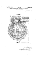
' In the hlOWIl transmitter, as shown in Fig. 1, an insulating disc S carries the entire angular division and on it are arranged unit contacts 6 to 6 at angular distances of 1 the one from the adj acent one. These contacts are uniformly distributed over a central angle which theoretically is 19 and practically is slightly greater on account of the width of the insulating gaps, but in any case does not exceed 20. These contacts are electrically connected in pairs, 6 being connected with e 6 with e 6 with e and so on, up to e, which is connected with 6 From each of the ten contacts 0 to e a wire leads to a numbered incandescent lamp G to G of the receiver E. Over these 20 unit contacts slide 360: 20 18 contact springs a to a all of which are electrically connected with each other having their contact points set exactly 360: 18=20 apart. These contact points are of such a width that they bridge the insulating gap between two adjacent contact strips, whereby sparking due to the breaking of current is avoided. Inside and concentrically to the circle of unit contacts 6 are arranged 36 tens contact Z 'to'z each occupying a central angle of about 9 the width of the insulating gap between two adjacent tens contacts being about 1. Of these tens contacts are electrically connected with each other Z with Z Z with Z then Z with Z Z Z and so on up to Z with Z, and Z From each of the tens contacts Z, to Z, a wire leads to one of the ten numbered incandescent lamps G' G G up to G A contact spring I) having a contact point wide enough to bridge the insulation gaps slides over all the 36 tens contacts in succession. Inside and concentric to the circle of tens contacts Z are arrangedthe hundreds contact segments h k k h four in number, each of the segments being 1 7a., 15;, h, occupying a central angle of 99, while the segment It; occupies 59 the insulation gaps between these hundreds segments in width. Over these hundreds segments slides a contact springlc the contact oint of which is wide enoug to bridge the insulation gaps. From eac of these hundreds contact segments leads a wire to one of the numbered incandescent lamps G G Gm, G'eoo- One of the terminals of each of the 24 incandescent lamps of the transmitter is connected to the wire r leading to one terminal of the battery B. The other terminal of the latter is connected to a contact ring R inside and concentric to the ring formed ofthe hundreds segments h to h On this ring R slides the contact sprinfid. All of the 20 contact springs are secure to the pointer plate of the transmitter. Therefore in any position of the transmitter'one lamp of the hundreds set, one lamp'of the tens set and one of the units set will be lighted. Only if any of the contact springs is bridging one of the insulating gaps two lamps of the corresponding set will be lighted.
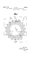
From Fig. 1 it will be seen that in this case the smallest possible circumference of the plate carrying the contactsmust be 360 times as at as the smallest possible unit contact. ow in order to enable me to reduce the size of the transmitter without varying the number of contacts and contact springs the units contacts for successive angle values which in Fig. 1 are located side by side, are arranged according to my present invention, as shown in Fig. 2 that is to say the angle occupied by each units .contact is equal to the angle between adjacent units contact points plus the theoretical angle of the units contact which in theexample givenis1 and hence is represented by 360: 18=20, 20+ =21. But as the total angle occupied by all the units contacts must not exceed 360 and as a uniform division of these 20 units contacts would give an angle of 19 X 21=399 these contact strips have to be divided into two groups the angle occupied by each contact being 21 but the two groupsbeingstaggered relatively to each other by 10. Therefore the units contacts are divided as follows: In the first group a to 6 with an angular'distance of 21 between two contact strips then between e, and a an angular distance of and for e up to 0 again an angular distance of 21. Consequently there is no uniform anlar distance between adjacent contact strips ut an angular distance varying between 10 and 21 10 11. The uniform division of the contact strips is found with a transmitting step of 1 when only 10 units contacts at an angular distance of 21 are used and 360: 10=36 contact springs at angular distances of 10. Now as the size of the transmitesa-n4.
ter mainly depends on the 0. ar distance of the units contacts and may the smaller the greater this angular distance is, this latter arrangement with 10 units contacts and 36 contact springs would be still more advan- 'i.) ta us than that shown in Fig. 2 having units contacts and 18 contact springs. e arrangement of the tens and hundreds contacts as also the electric connections with the numbered incandescent lamps are the same as those shown in Fig. 1.
Assuming that the electric transmitter shown in Fig. 1 is adjusted to any angle, say 135, no matter whether this angle is known to the o rator or whether the transmitter is adjusted to this angle automatically and unknown to the operator, say by adjusting a telescope or the like to a given point starting, from a given zero position, then as shown in V Fig. 3, startin from a given initial tion, the hundreds rush a will contact t e hundreds segment h, and the tens brush 6 will con tact the tens contact plate 2 while one of the units brushes a will contact the units contact 0 whereby the incandescent lamps G G v and G are lighted, thereby indicating at the receiver station the angle of 135 to which the transmitter has been adjusted.
If now the transmitter constructed in accordance with my invention and shown in Fig. 2 is adjusted as above set forth to the same s angle of 135 starting from its initial tion then, as shown in Fig. 4, the ban reds brush 0 will again contact the hundreds seg ment h, the tens brush b will contact the tens segment 2 and the units brush a will contact the units contact 0 whereb the same as in the case of the transmitter s own in Fi 1, the incandescent lam s G G and s will be lighted, thus, of course, again indicating at the receiving station the angle of 135" But while in the transmitter shown in Figs. 1 and 3 the units contacts are thronged in a small fraction of the circumference of a circle thereby necessitating a large radius of 110 the circle for accommodatin the required number of units contacts an their insulations, and determining the minimum width; in my improved transmitter shown in Figs. 2 and 4 the necessary number of units contacts is distributed over the entire circumference of a circle, so that the radius of the circle may be made much smaller without unduly reducing the width of the individual units contact segments. Moreover the insulation between successive units contacts need not be cared for since these insulations are more than sufliciently wide. Thus it will be seen that by my present invention the construction of the transmitter is greatly facilitated and at the same time its accuracy and reliability is greatly increased.
What I claim is Electric transmitter for transmitting values of angles differing by small increments the 130 said 'values being represented by units, tens, hundreds and so on groups, comprising a se arate contact group associated to each of the first named groups, such contact grou being arranged in concentric rings, equidistant contact springs sliding on the units contact ring, the angle between the centers of two successive contacts being equal to the theoretical units division angle plus at least one time the angular distance between adjacent units contact springs.
In testimony whereof I afl'ixed my signature.
RUDOLF LANG,
Applications Claiming Priority (1)
| Application Number | Priority Date | Filing Date | Title |
|---|---|---|---|
| DE1853734X | 1929-02-11 |
Publications (1)
| Publication Number | Publication Date |
|---|---|
| US1853734A true US1853734A (en) | 1932-04-12 |
Family
ID=7746119
Family Applications (1)
| Application Number | Title | Priority Date | Filing Date |
|---|---|---|---|
| US425051A Expired - Lifetime US1853734A (en) | 1929-02-11 | 1930-01-31 | Electric transmitter for transmitting values of angles |
Country Status (1)
| Country | Link |
|---|---|
| US (1) | US1853734A (en) |
Cited By (2)
| Publication number | Priority date | Publication date | Assignee | Title |
|---|---|---|---|---|
| US2812994A (en) * | 1955-11-14 | 1957-11-12 | Sylvania Electric Prod | Lead-in wire contacting apparatus |
| US2922994A (en) * | 1957-03-18 | 1960-01-26 | F L Moseley Co | Electrical signal generators |
-
1930
- 1930-01-31 US US425051A patent/US1853734A/en not_active Expired - Lifetime
Cited By (2)
| Publication number | Priority date | Publication date | Assignee | Title |
|---|---|---|---|---|
| US2812994A (en) * | 1955-11-14 | 1957-11-12 | Sylvania Electric Prod | Lead-in wire contacting apparatus |
| US2922994A (en) * | 1957-03-18 | 1960-01-26 | F L Moseley Co | Electrical signal generators |
Similar Documents
| Publication | Publication Date | Title |
|---|---|---|
| US3984922A (en) | Rotors | |
| GB604710A (en) | Improvements in electrical selector switch devices | |
| GB726578A (en) | Improvements in or relating to variable resistance devices | |
| US1665857A (en) | Electrical transmission system | |
| US2707222A (en) | Voltage divider | |
| US1853734A (en) | Electric transmitter for transmitting values of angles | |
| US2786122A (en) | Resistance unit | |
| US1537281A (en) | Electrical measuring apparatus | |
| US2283951A (en) | Commutator oscillograph device | |
| US2884505A (en) | Variable control for electrical impedance assemblies | |
| US4388758A (en) | Digital electrical angle-measuring device | |
| US3004251A (en) | Digital-to-analogue converter | |
| US1361676A (en) | Measuring and indicating apparatus | |
| US1954955A (en) | Electrical recording device | |
| US3355806A (en) | Test standard device for discrete angle values | |
| US2762016A (en) | Rotary distributors | |
| US2806928A (en) | Adjustable precision potentiometers | |
| US2339116A (en) | Temperature measuring apparatus | |
| US2428389A (en) | Data transmission system | |
| US2423829A (en) | Indicating system | |
| US1913992A (en) | Switching device | |
| US2285969A (en) | Telemetric system | |
| US2125491A (en) | Electrical signaling system | |
| US2351441A (en) | Electrical testing | |
| US2985859A (en) | Continuously variable resistance apparatus |