US1853727A - Wrist pin - Google Patents
Wrist pin Download PDFInfo
- Publication number
- US1853727A US1853727A US422010A US42201030A US1853727A US 1853727 A US1853727 A US 1853727A US 422010 A US422010 A US 422010A US 42201030 A US42201030 A US 42201030A US 1853727 A US1853727 A US 1853727A
- Authority
- US
- United States
- Prior art keywords
- bearing
- housing
- wrist pin
- members
- pin
- Prior art date
- Legal status (The legal status is an assumption and is not a legal conclusion. Google has not performed a legal analysis and makes no representation as to the accuracy of the status listed.)
- Expired - Lifetime
Links
Images


Classifications
-
- F—MECHANICAL ENGINEERING; LIGHTING; HEATING; WEAPONS; BLASTING
- F16—ENGINEERING ELEMENTS AND UNITS; GENERAL MEASURES FOR PRODUCING AND MAINTAINING EFFECTIVE FUNCTIONING OF MACHINES OR INSTALLATIONS; THERMAL INSULATION IN GENERAL
- F16C—SHAFTS; FLEXIBLE SHAFTS; ELEMENTS OR CRANKSHAFT MECHANISMS; ROTARY BODIES OTHER THAN GEARING ELEMENTS; BEARINGS
- F16C23/00—Bearings for exclusively rotary movement adjustable for aligning or positioning
- F16C23/02—Sliding-contact bearings
Definitions
- My invention relates to Wrist pins, and more particularly to wrist pins of the type employed in oil field-equipment-dior connecting the walkingheam pit-man with its opera-t:
- a Fig. 2 is a .orosssectional-View through the bearingand wrist ipinon theljine 22, 1.
- Fig. 4 is a disassociated, perspective View of :the component parts of thebearing housing.”
- Fig. 5 is adet ail, perspective View of the bearingsleeve membersandthe lower wedge for adjusting :the bearing.
- : -l designates:the lower end of a oran'k having a tapered opening 2 forreoeiving a wrist pin 3 comprising a cylindrical bearing portion havingataperedl end 5 complementary to the tapered bore 2 in the crank, the wrist pin :being retained in the looreby a nut 6 threaded onan extension #7 projecting from the end of the tapered portion and "en-gaging :the inner face of the crank to draw the tapered portion of the pin tightly into the opening 2 :to prevent rotation of the pin in the opening during operationoi the crank.
- 'lrh :hO S hg -6 pre rab y includes a rectan guh r lwk :17 aying a 'longzitudiu ibore 1'8 o substa tially larger d ame e than the ph r c l por ion of b aring memb rs 10 and l r aee mmode inge llar members 1 .9 and 20;
- the inner ;surfa.ces, o (the .oollars between the plates end-the ooncayeseats are preferb Xf iPQ 'Q I011l3W3ld1y.. OtZer the ends of the bealzmg members asat ,31..t.o provide free roeking movement of the :housing ton-the wrlstzplm.
- V Elie innerplate23 is .preferablyprovided w t can Lannularerecess -32 about the .W ist pin, and eeeived @therei-niand engaging the eoneave (interface ofthe eollarzisa Washer.
- wedge-shaped blocks 48 and 49 for adjusting the bearing sleeve on the wrist pin.
- the wedge block 48 is preferably provided with a concave recess 50 to seat on the upper periphery of the sleeve member 10 which is exposed through the slots, and the wedge 49 is received on and adapted for sliding engagement with the wedge 48 by a set screw 51 threaded through the plate '24.
- the end of the set screw 51 bears against the wedge block 49 so that when the screw is rotated in the plate the wedge 49 sliding between the bottom of the groove 45 and the inclined face of the wedge 48 moves'the bearing members closer to the wrist pin to compensate for the wear that may occurbetween the parts;
- the screw may be locked in adjusted position by a lock nut 52 received thereon and adapted to be tightened against the plate.
- I provideset screws 53 and 54, the set screw 53 being threaded through an opening 55 formed in the lower side of the block 17 and through aligning notches 56 and 57 in the abutting ends of the collars 19 and 20, and the end is loosely received in a recess 58 formed in the bearing member 11.
- the screw 54 is threaded through the lower wedge 48 into a recess 59 provided in the outerfaces of the bearing member 10.
- I enclose the stud 37 with acap 60 having a laterally projecting flange 61 for attaching the cap to the plate 24', the capbeing retain'ed'by screws 62 projected through openings 63 in the flange and into threaded openings 64 formed in the outer side of the plate24;
- Formed on the outer end of the cap is a vertical boss 65 having a port 66 through which lubricant may be admitted into the cap 60, the port being closed by a cap screw 67 threaded 1n its outer end.
- the wrist pin is inserted in the opening 2 of the crank and retained by the nut 6.
- the washer 33 and the collar 19 are then sleeved on the wrist pin and the stud bolts 25 are threaded into the openings 28 formed in the plate 23.
- the block 17 is then sleeved on the projecting ends of the stud bolts, after which the wedges 48 and 49 are assembled on the bearing member 10 and the bearing members 10 and 11 are then sleeved on the wrist pin and seated against the collar 19.
- the collar 20 is then sleeved over the stud 39 and seated against the bearing members 10 and 11.
- the nuts 29 are then threaded on the projecting ends of the stud bolts 25 to retain the parts in assembled relation.
- the washers 39 and 40 including the spring 43 are. sleeved on the stud 37 and the lock nuts 44 are then threaded on the stud to tension the spring.
- the cap 60 is then applied and the lubricant is inserted through the ports 66 to the interior of the bearing through theopening 36 in the plate 24.
- the housing being mounted for universal inovement'on the bearing sleeve will accommodate itself to irregularity of movement of the crank or pitman which may occur and thereby avoid binding and resultant loss of power or damage to the connecting parts.
- a bearing for the wrist pin comprising a split sleeve on the pin, a bearing housing carried by the pitman, means mounting the housing on the sleeve to provide universal movement of the pitman with relation to the pin, means yieldingly retaining the bearing against, longitudinal movement on the pin, and adjusting means: for contracting the sleeve on the pin.
- a wrist pin having a bearing portion, bearing members on the bearing portion having semi-spherical body portions, a housing having a cylindrical bore, end members in the bore, and having annular seats for engaging the semi-spherical portions of the bearing members and aligning recesses, wedges slidable in the recesses for adjusting the bearing members, and screw-actuated means for actuating the wedges.
- a wrist pin having a bearing portion, bearing members on the bearing portion having semi-spherical body portions, a housing having a cylindrical bore, end members in the bore having annular seats for engaging the semi-spherical portions of the bearing members and aligning recesses, wedges slidable in the recesses for adjusting the bearing members, means for actuating the wedges,
- a wrist pin having a bearing portion
- bearing members on the bearing portion having semi-spherical body portions, a housing for enclosing the bearing members, collars in the housing and having concave annular seats engaging the body portions of the bearing members, means for preventing longitudinal movement of the bearing members in the housing, and wedge means slidably mounted in the housing for adjusting the bearing members on the bearing portion of the pin.
- a wrist pin having a bearing portion, bearing members on the bearing portion having semi-spherical body portions, a housing for enclosing the bearing members, collars in the housing having concave annular seats engaging the body portions of the bearing members, means for preventing longitudinal movement of the bearing members in the housing, wedge means slidably mounted in the housing for adjusting the bearing members on the bearing portion of the pin, and screw-actuated means for moving the wedges.
- a wrist pin having a bearing portion, a bearing sleeve on the bearing portion, a housing enclosing the sleeve and having universal mounting thereon, a stud extending from the outer end of the Wrist pin, washers on the stud, a spring sleeved on the stud and. received between the washers, and means for tensioning the spring to yieldingly retain the housing against longitudinal movement on the wrist pin.
- a wrist pin having a bearing portion and a tapered attaching portion and a stop collar separating said portions
- bearing members on the bearing portion of the pin having substantially semi-spherical body portions
- a housing enclosing the bearing members
- sealing means between the housing and the collar means in the housing engaging the body portions of the bearing members, and yielding means for retaining the housing in sealing engagement with the collar on the wrist pin.
- a wrist pin bearing including upper and lower bearing members having substantial semi-spherical body portions, collars having concave annular seats engaging the body portions of the bearing members and having aligning slots, a wedge received in said slots and having a concave recess for engaging one of the bearing members, means for retaining the Wedge against lateral movement with relation to the bearing member, and a second wedge slidable in said'slots and engaging the first wedge for radially adjusting the bearing members.
Landscapes
- Engineering & Computer Science (AREA)
- General Engineering & Computer Science (AREA)
- Mechanical Engineering (AREA)
- Pivots And Pivotal Connections (AREA)
Description
April 12, 1932. H. H. FRANKS 1,353,727
WRIST PIN Filed Jan. 20, 1930 3 Sheets-Sheet l [N VENTOR ATTORNEY April 12,1932. FRANKS 1,853,727-
V WRIST PIN Filed Jan. 20, 1930 3 SheetsSheet 2 4539910 59 54, 4 6 15 2a 5. IHIIIIHIIIINHMIl/HMIl/flll/M 27 April 12, 1932. u H. H. FAwKs 1,853,327
WRIST PIN.
Filed Jan. 20, 1930 s Sheets-Shegb s,
[N VEN TOR 0/ hi 00M TTORNEY Patented Apr. 12, 19 32 HARRY t lhwxs 10. These QKLAHQMA, ess e pe e whimenses T 1 4 9 9. .1.. .GOMRANEQF TULSA, .9K eAfl A AG9BR BJtTIQ r PEI-elem WRIT rm 'hpplioation filed January '20, 199i); Serial No. 422,0}0.
My invention relates to Wrist pins, and more particularly to wrist pins of the type employed in oil field-equipment-dior connecting the walkingheam pit-man with its opera-t:
5 ingcrank .of a well rig-the principal object of the invention being to eliininatetorsional strains on .awrist pin due to misalignment of the walking beam or its operating crank.
In accomplishing this and other obj eots of the invention; I have providedimprowed de tails of-struotui'e, the preferred fonmof which is illustrated in the accornp anying drawings, wherein:
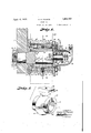
1 is a Vertical soot-ion through a por- 1'5 tionof axor-ank and its pitman illustrating .a
wrist pin and wrist pin .bearingeembodying myiinvention. f
a Fig. 2 is a .orosssectional-View through the bearingand wrist ipinon theljine 22, 1.
ig. 3 is a horizontal sectional =vieW through the bearing housing on :theiliner3.3,
Fig. 2.
Fig. 4 is a disassociated, perspective View of :the component parts of thebearing housing."
Fig. 5 'is adet ail, perspective View of the bearingsleeve membersandthe lower wedge for adjusting :the bearing.
. Referring more in-detail tothedrawings:
: -l designates:the lower end of a oran'k having a tapered opening 2 forreoeiving a wrist pin 3 comprising a cylindrical bearing portion havingataperedl end 5 complementary to the tapered bore 2 in the crank, the wrist pin :being retained in the looreby a nut 6 threaded onan extension #7 projecting from the end of the tapered portion and "en-gaging :the inner face of the crank to draw the tapered portion of the pin tightly into the opening 2 :to prevent rotation of the pin in the opening during operationoi the crank.
I FOrmedon thewrist pin ibetween the bearing portion A; and the tapered portion *5 isia stop 1 collar. '8 having xa iconcave outer :Eaoe 9 for a purpose later .-described.
Received on the bearing portion the wrist pin; are upper and ,lo werhearingemenrhers 10;. nd 11 1 vwhich,eo s it t substantially ,,=cylindrica:1 :hea ing sleeve: 12 2for the a ela, endiformed onthe. 0111 P P -Y 0f the hearing m mherS mid-Way of their, length QSu stan iwlly semirlspherica-l .QOlr gendle t e housing lfinow deseri-bed. 'lrh :hO S hg -6 pre rab y includes a rectan guh r lwk :17 aying a 'longzitudiu ibore 1'8 o substa tially larger d ame e than the ph r c l por ion of b aring memb rs 10 and l r aee mmode inge llar members 1 .9 and 20; The collar members .are sleeved'in oppos teen l t the bore l8s m the ainne times e Prov ded t ennui er encay seats 21. e i22 vfe sn sly ree vi gthe Spherical p f lO l f t h aillg memher so that thehouewe; i qckflm y rock ad-E ly o the spher eel' portions of the hearing members. ord to reta n the selle members in ea i g re a io w th th bearing m mbe s, t col r a d "20 rare pre erably ,ptod d 0 13119 1 ute end w theint gre n ule pla es 23 and A which a e :seeured t -th en of th ihloqk y stud b lt 5- lh b lts 2 prefi rahly ext nd threug'h Qpe ng -26 pr ided i ithe qui plate 2.4 nd .thrhug iopening 2 e tendi g longitud nelly-t roug gthe'icq nersei th ihl-ock-end a ed inthreaded.openingsrZB formed. th @lete .21 -"he bolts-25am of sulfic n l gth to pretrudeath ough the .plate 2 an the b ock .c' emped between the platesby nuts29 threaded on theprojeoting ends ;.0 f:z hzb.o1t s :as. clearly showngin Fi ,-.3,-. {E116 'hQll g membe ab ve described. is ye e -ve iinf reQtangflarQ e i g-BO formed in the @pitman :13, and th upper and lower dge fth p'lates 2.3 and 2epreferahly pro- J beyon he upper ELIl JQWBUS dQS lot the b10clQt0-retainthe .housingin the pitman as shown in Fig. {1, V v
The inner ;surfa.ces, o (the .oollars between the plates end-the ooncayeseats are preferb Xf iPQ 'Q I011l3W3ld1y.. OtZer the ends of the bealzmg members asat ,31..t.o provide free roeking movement of the :housing ton-the wrlstzplm. V Elie innerplate23 is .preferablyprovided w t can Lannularerecess -32 about the .W ist pin, and eeeived @therei-niand engaging the eoneave (interface ofthe eollarzisa Washer. .33:havinglaconizexeeuter face cemplemene tary to' the; soncaevityofthe oolbar 8;:fonsea1- sion spring 43 which is also sleeved on the" stud. The spring is tensioned by lock nuts 44 threaded on the end of the stud, so that the spring exerts pressure on the housing to retain the washer in seating engagement with the collar 8 and prevent its outward longitudinal movement onthe wrist pin.
' Formed in the housing at the upper portion of the bore 18'is a rectangular slot or groove 45 aligning with complementary slots 46 and 47 formed in the collars 19 and 20, as shown in Fig. 4, and received therein are wedge-shaped blocks 48 and 49 for adjusting the bearing sleeve on the wrist pin. The wedge block 48 is preferably provided with a concave recess 50 to seat on the upper periphery of the sleeve member 10 which is exposed through the slots, and the wedge 49 is received on and adapted for sliding engagement with the wedge 48 by a set screw 51 threaded through the plate '24. The end of the set screw 51 bears against the wedge block 49 so that when the screw is rotated in the plate the wedge 49 sliding between the bottom of the groove 45 and the inclined face of the wedge 48 moves'the bearing members closer to the wrist pin to compensate for the wear that may occurbetween the parts; The screw may be locked in adjusted position by a lock nut 52 received thereon and adapted to be tightened against the plate.
In order to retain the sleeve members 10 and 11 against longitudinal movement and yet provide for rocking movement of the housing on the spherical portions of the sleeve members, I provideset screws 53 and 54, the set screw 53 being threaded through an opening 55 formed in the lower side of the block 17 and through aligning notches 56 and 57 in the abutting ends of the collars 19 and 20, and the end is loosely received in a recess 58 formed in the bearing member 11.
The screw 54 is threaded through the lower wedge 48 into a recess 59 provided in the outerfaces of the bearing member 10.
In orderto lubricate the bearing and to re-' tain the lubricant therein, I enclose the stud 37 with acap 60 having a laterally projecting flange 61 for attaching the cap to the plate 24', the capbeing retain'ed'by screws 62 projected through openings 63 in the flange and into threaded openings 64 formed in the outer side of the plate24; Formed on the outer end of the cap is a vertical boss 65 having a port 66 through which lubricant may be admitted into the cap 60, the port being closed by a cap screw 67 threaded 1n its outer end.
In assembling a wrist pin and bearing constructed as described, the wrist pin is inserted in the opening 2 of the crank and retained by the nut 6. The washer 33 and the collar 19 are then sleeved on the wrist pin and the stud bolts 25 are threaded into the openings 28 formed in the plate 23.,
The block 17 is then sleeved on the projecting ends of the stud bolts, after which the wedges 48 and 49 are assembled on the bearing member 10 and the bearing members 10 and 11 are then sleeved on the wrist pin and seated against the collar 19. The collar 20 is then sleeved over the stud 39 and seated against the bearing members 10 and 11. The nuts 29 are then threaded on the projecting ends of the stud bolts 25 to retain the parts in assembled relation. The washers 39 and 40 including the spring 43 are. sleeved on the stud 37 and the lock nuts 44 are then threaded on the stud to tension the spring.
The cap 60 is then applied and the lubricant is inserted through the ports 66 to the interior of the bearing through theopening 36 in the plate 24.
- The housing being mounted for universal inovement'on the bearing sleeve will accommodate itself to irregularity of movement of the crank or pitman which may occur and thereby avoid binding and resultant loss of power or damage to the connecting parts.
I/Vhat I claim and desire to secure by Letters Patent is:
1. In combination with a wrist pin and a pitman, a bearing for the wrist pin comprising a split sleeve on the pin, a bearing housing carried by the pitman, means mounting the housing on the sleeve to provide universal movement of the pitman with relation to the pin, means yieldingly retaining the bearing against, longitudinal movement on the pin, and adjusting means: for contracting the sleeve on the pin.
2. In a wrist pin having a bearing portion, bearing members on the bearing portion having semi-spherical body portions, a housing having a cylindrical bore, end members in the bore, and having annular seats for engaging the semi-spherical portions of the bearing members and aligning recesses, wedges slidable in the recesses for adjusting the bearing members, and screw-actuated means for actuating the wedges. v
3. In a wrist pin having a bearing portion, bearing members on the bearing portion having semi-spherical body portions, a housing having a cylindrical bore, end members in the bore having annular seats for engaging the semi-spherical portions of the bearing members and aligning recesses, wedges slidable in the recesses for adjusting the bearing members, means for actuating the wedges,
and means engaging one of theend members for yieldingly retaining the housing from longitudinal movement on the pin.
4. A wrist pin having a bearing portion,
bearing members on the bearing portion having semi-spherical body portions, a housing for enclosing the bearing members, collars in the housing and having concave annular seats engaging the body portions of the bearing members, means for preventing longitudinal movement of the bearing members in the housing, and wedge means slidably mounted in the housing for adjusting the bearing members on the bearing portion of the pin.
5. A wrist pin having a bearing portion, bearing members on the bearing portion having semi-spherical body portions, a housing for enclosing the bearing members, collars in the housing having concave annular seats engaging the body portions of the bearing members, means for preventing longitudinal movement of the bearing members in the housing, wedge means slidably mounted in the housing for adjusting the bearing members on the bearing portion of the pin, and screw-actuated means for moving the wedges.
6. In a wrist pin having a bearing portion, a bearing sleeve on the bearing portion, a housing enclosing the sleeve and having universal mounting thereon, a stud extending from the outer end of the Wrist pin, washers on the stud, a spring sleeved on the stud and. received between the washers, and means for tensioning the spring to yieldingly retain the housing against longitudinal movement on the wrist pin. 1
7 In a wrist pin having a bearing portion and a tapered attaching portion and a stop collar separating said portions, bearing members on the bearing portion of the pin having substantially semi-spherical body portions, a housing enclosing the bearing members, sealing means between the housing and the collar, means in the housing engaging the body portions of the bearing members, and yielding means for retaining the housing in sealing engagement with the collar on the wrist pin.
8. In a wrist pin bearing including upper and lower bearing members having substantial semi-spherical body portions, collars having concave annular seats engaging the body portions of the bearing members and having aligning slots, a wedge received in said slots and having a concave recess for engaging one of the bearing members, means for retaining the Wedge against lateral movement with relation to the bearing member, and a second wedge slidable in said'slots and engaging the first wedge for radially adjusting the bearing members.
In testimony whereof I afiix my signature.
HARRY H. FRANKS.
Priority Applications (1)
| Application Number | Priority Date | Filing Date | Title |
|---|---|---|---|
| US422010A US1853727A (en) | 1930-01-20 | 1930-01-20 | Wrist pin |
Applications Claiming Priority (1)
| Application Number | Priority Date | Filing Date | Title |
|---|---|---|---|
| US422010A US1853727A (en) | 1930-01-20 | 1930-01-20 | Wrist pin |
Publications (1)
| Publication Number | Publication Date |
|---|---|
| US1853727A true US1853727A (en) | 1932-04-12 |
Family
ID=23673014
Family Applications (1)
| Application Number | Title | Priority Date | Filing Date |
|---|---|---|---|
| US422010A Expired - Lifetime US1853727A (en) | 1930-01-20 | 1930-01-20 | Wrist pin |
Country Status (1)
| Country | Link |
|---|---|
| US (1) | US1853727A (en) |
Cited By (4)
| Publication number | Priority date | Publication date | Assignee | Title |
|---|---|---|---|---|
| US3160449A (en) * | 1961-12-28 | 1964-12-08 | Metallized Carbon Co Inc | Self-alining bearings |
| US4682938A (en) * | 1985-12-26 | 1987-07-28 | Sundstrand Corporation | Gear pump bearings |
| US5524987A (en) * | 1993-12-20 | 1996-06-11 | Rexnord Corporation | Plugged slotted entry bearing |
| US20110033230A1 (en) * | 2008-04-14 | 2011-02-10 | Zf Friedrichshafen Ag | Joint and/or bearing arrangement |
-
1930
- 1930-01-20 US US422010A patent/US1853727A/en not_active Expired - Lifetime
Cited By (5)
| Publication number | Priority date | Publication date | Assignee | Title |
|---|---|---|---|---|
| US3160449A (en) * | 1961-12-28 | 1964-12-08 | Metallized Carbon Co Inc | Self-alining bearings |
| US4682938A (en) * | 1985-12-26 | 1987-07-28 | Sundstrand Corporation | Gear pump bearings |
| US5524987A (en) * | 1993-12-20 | 1996-06-11 | Rexnord Corporation | Plugged slotted entry bearing |
| US20110033230A1 (en) * | 2008-04-14 | 2011-02-10 | Zf Friedrichshafen Ag | Joint and/or bearing arrangement |
| US8783993B2 (en) * | 2008-04-14 | 2014-07-22 | Zf Friedrichshafen Ag | Joint and/or bearing arrangement |
Similar Documents
| Publication | Publication Date | Title |
|---|---|---|
| DE2061063C3 (en) | Frictional connection between a drive head and a piston rod | |
| DE19847842B4 (en) | ball joint | |
| US10648337B2 (en) | Eccentric screw pump | |
| US1853727A (en) | Wrist pin | |
| US2200641A (en) | Coupling | |
| DE2403111A1 (en) | JOINT CONNECTION | |
| US3481159A (en) | Universal joint with elastomeric bearing race mounting and a two part yoke | |
| US1130982A (en) | Connecting-rod. | |
| US3431751A (en) | Anti-backlash universal joint | |
| US3369848A (en) | Anchor end pivotal connection for idler arms | |
| USRE17838E (en) | gayman | |
| DE2434501A1 (en) | External support sleeves of elastic ball joint location - are axially clamped to produce radial rubber flange | |
| US1985728A (en) | Ball and socket joint | |
| US1363477A (en) | Pivot or knuckle joint connection | |
| US3213644A (en) | Universal joint | |
| US2811861A (en) | Adapter coupling means | |
| US210646A (en) | Improvement in pitman-connections | |
| US1924326A (en) | Bearing for eccentrics | |
| US1868817A (en) | Pitman bearing assembly | |
| US2381938A (en) | Battery terminal | |
| US1996996A (en) | Universal joint | |
| DE102017118233A1 (en) | Ring tensioner with tensioning roller-positioning adjustment means | |
| DE3841153A1 (en) | ARRANGEMENT OF THE AXLE BEARINGS IN A DRIVE FOR RAIL VEHICLES | |
| US3302267A (en) | Method of preloading a universal joint | |
| DE2052788A1 (en) | Hydraulic clamping nut with mechanical locking |