US1853720A - Mold for building blocks - Google Patents
Mold for building blocks Download PDFInfo
- Publication number
- US1853720A US1853720A US525690A US52569031A US1853720A US 1853720 A US1853720 A US 1853720A US 525690 A US525690 A US 525690A US 52569031 A US52569031 A US 52569031A US 1853720 A US1853720 A US 1853720A
- Authority
- US
- United States
- Prior art keywords
- mold
- sides
- core
- blocks
- core members
- Prior art date
- Legal status (The legal status is an assumption and is not a legal conclusion. Google has not performed a legal analysis and makes no representation as to the accuracy of the status listed.)
- Expired - Lifetime
Links
- 238000005192 partition Methods 0.000 description 5
- 150000001875 compounds Chemical class 0.000 description 4
- 239000004568 cement Substances 0.000 description 3
- 239000002184 metal Substances 0.000 description 3
- 238000010276 construction Methods 0.000 description 2
- 230000007423 decrease Effects 0.000 description 1
- 230000004048 modification Effects 0.000 description 1
- 238000012986 modification Methods 0.000 description 1
Images
Classifications
-
- B—PERFORMING OPERATIONS; TRANSPORTING
- B28—WORKING CEMENT, CLAY, OR STONE
- B28B—SHAPING CLAY OR OTHER CERAMIC COMPOSITIONS; SHAPING SLAG; SHAPING MIXTURES CONTAINING CEMENTITIOUS MATERIAL, e.g. PLASTER
- B28B7/00—Moulds; Cores; Mandrels
- B28B7/28—Cores; Mandrels
- B28B7/30—Cores; Mandrels adjustable, collapsible, or expanding
- B28B7/303—Cores; Mandrels adjustable, collapsible, or expanding specially for making undercut recesses or continuous cavities the inner section of which is superior to the section of either of the mouths
-
- B—PERFORMING OPERATIONS; TRANSPORTING
- B28—WORKING CEMENT, CLAY, OR STONE
- B28B—SHAPING CLAY OR OTHER CERAMIC COMPOSITIONS; SHAPING SLAG; SHAPING MIXTURES CONTAINING CEMENTITIOUS MATERIAL, e.g. PLASTER
- B28B7/00—Moulds; Cores; Mandrels
- B28B7/24—Unitary mould structures with a plurality of moulding spaces, e.g. moulds divided into multiple moulding spaces by integratable partitions, mould part structures providing a number of moulding spaces in mutual co-operation
- B28B7/241—Detachable assemblies of mould parts providing only in mutual co-operation a number of complete moulding spaces
Definitions
- My invention relates to molds for making cement building blocks and more particularly to the cores which form the spaces or openings between portions of the blocks. It is one object of this invention to provide a sheet-metal core of frusto-pyramidal shape. The sides of the core are preferably made integral with one end thereof so that the former are resilientlyheld in expanded condition. Another object is to provide a simple and eflicient means for moving'the sides of a core toward each other in order to detach them from the sides of the block in contact therewith in the mold. Further objects appear hereinafter.
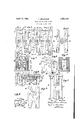
- Fig. l' isa plan view of a compound mold having three mold compartments equipped with my invention; Fig. 2, a section on the line 22 on'Fig. 1; Fig. 8, a plan view of. a building block made in one of the compartments;
- Fig. 5 a perspective view of one of the cores
- Fig. 6, an enlarged horizontal section on the'line 66 on Fig. 2
- Fig. 7 a fragmentary view showing a plan view of a modification of Figs. 1, 3, and 5
- Fig. 8 a plan view of a building block made in the mold shown in Fig. 7 and Fig. 9, a detailed view showing the relation between the tieplate 14 and one of the core members 16.
- I show a compound mold with the vertical sides 1 and 2 and the ends 3 and 4, the latter having flanges 5 overlapping the sides and secured thereto by the screws or pins 6.
- the compound mold is divided into a number of individual mold spaces or compartments 7 8,
- This compartment is bounded laterally by One building block that can be made in compartment 7 shown in'Figs. "3 and l. 'It comprises the twolateral parts 12 tied together in spaced'relation by the tie-rod l3 and the tie-plate 14 near the opposite ends of the block. I prefer that at least one ofthe ties shall be a plate-rod to provide the block witha stronger resistance to'twisting strains.
- the tie-plate has its ends provided with flanges which anchor it firmly in the block. It will be noted from Fig. 4 that the tie-plate has the cen'tral'recess 15 positioned between opposing faces of the parts 1210f the block.
- Each ,of the sides 1' and 2 have attached thereto a sheet-metal core member '16 inthe form of a "frustrum of a pyramid.
- One core is-attachedto each side 1 and 2 and projects horizontally into the compartment 7 with their opposing smaller ends inmutual engagement.
- the tie-rod- 13 rests in grooves 17 in the smaller ends 18 of the core members.
- the inner faces' of the blocks20 are each provided with a pair of screws 24 for rigidly fastening to the blocks the triangular'metal' loops 25, each having one angle projecting into the space between the two blocks.
- 26 is a horizontal shaft rotatable in the side 1 andprovided at its inner end with the loop 27 which is, interlooped with the two inner anglesof the loops 25' as shown in Figs. 2 and 6;
- the shaft 26' is operatedby the handle. 28 beyond the outer face of the side l.
- the blocks 20 are slidable upon and guided by the screws 23.
- the inner face of the side 1 is provided with the'two ribs 29 whose lower faces are These blocks have I the sides 1 and2,-the end'3, and the partition 2 in contact with the upper ends of. the sides 19-of the core member 16.
- The'depth of the inclined 'ribs29 'decreases'tow'ard'the shaft26 so that when the two core members 16 in the compartment 7 are placed with their ends 18 against each other, the outer ends of the side 19 of the mold members will ride upon the inclined ribs 29 and force the two mold members toward each other causing their ends 18 to be without any space between them for the reception of concrete.
- Small angle-plates 33 are secured to the inner faces of the sides 1 and 2 and form stops against which the sides of the extensions 30 engage when the core members 16 are fully expanded. They prevent cement from entering the core members.
- the upper and lower faces of the mold member 16 are somewhat'narrower than the space between the sides 19 whereby extensions 30 are formed, the base of one extension having thegroove 17 and the other extension receiving the tie-plate which follows the contour of the extension as shown in Fig. 9.
- the upper and lower ends 31 of the extensions 30 are distant continuations of the sides 19. These ends which lie at the top and bottom of the compartment 7 overlap as shown in Figs. 1, 2, and 5. These ends slightlydoverlap the upper and lower edges of the si e 1.
- the two core members are assembled end to end in the compartment 7 as shown in Fig. 1 between the sides 1 and 2 and the end 3 and a partition 10, the tie-rod 13 being held between the two core members and the lower ends of the extensions 30 fitting the recess 15.
- the handle 28 is turned to cause the sides of the loop 27 to operate against the opposing faces of the blocks 20 and force the blocks 20 outwards with the sides 29 outwardly along the inclined ribs 29.
- the loop 27 stands squarely across the space between the two blocks 20 and locks them in their spaced relation. Wetcement is then poured into the compartment 7 at both sides of the core which is composed of two core members 16.
- the ends 3 are removed from the mold and the two handles 28 in the sides 1 and 2 are rotated to cause the loop 27, by acting in the inner angles of the loops 25 as shown in Fig. 2, to pull the two blocks 20 toward each other whereby the sides 19 are detached from the building block cast in contact therewith.
- the sides 1 and 2 are then pulled away from the blocks, the core members coming out with the sides.
- WVhile I have described in detail only a single mold compartment and a single core member it will be readily understood that the other compartments 8 and 9 can have assembled therein core members 16 with their tierods and tie-plates 14 so that building blocks may be cast in the compartments 8 and 9.
- Fig. 7 shows a mold compartment for easting the block shown in Fig. 8.
- the con struction of the core members 16 is the same as that for the core members 16 except that the opposing ends of the core members 16' are spaced apart so that the web 32 of the block shown in Fig. 8 may be cast integral with the two members 12 of the block.
- the tie-rod and the tie-plate are not employed.
- a core member carried by each side, the core members being constructed and arranged to have their inner ends abutting when the mold is assembled, and the opposite sides of the core members being movable toward and away from each other, means for forcing the said sides of the core member away from each other, and means cooperating with the sides of the mold and the core members to force the inner ends of the core members tightly together when the sides of the core members are forced away from each other.
- a side therefor a core having two opposite sides movable toward and away from each other, a block attached to the inner face of each core-side at its outer end, pins insertedthrough slots in the blocks and anchored in the side of the mold and having heads to connect the blocks to the side of the mold, the slots guiding the blocks and sides of the core in their movements toward andaway from each other, a loop carried by each block and projecting toward each other, a shaft extending into the side of the mold and having a loop interlooped with the loops in the block for actuating the blocks toward each other, and means for operating the shaft.
Landscapes
- Engineering & Computer Science (AREA)
- Manufacturing & Machinery (AREA)
- Chemical & Material Sciences (AREA)
- Ceramic Engineering (AREA)
- Mechanical Engineering (AREA)
- Moulds, Cores, Or Mandrels (AREA)
Description
April 1932- A. BRUCKNER v 1,853,720
MOLD FOR BUILDING BLOCKS Filed March 27, 1931 Patented Apr. 12, 1932 UNI D STATES ALBERT BRUCKNER, or ETNA," PENNSYLVANIA MOLD FOR BUILDING BLOCKS 1, Application filed March 27, 1931. Serial o. szaeeo.
My invention relates to molds for making cement building blocks and more particularly to the cores which form the spaces or openings between portions of the blocks. It is one object of this invention to provide a sheet-metal core of frusto-pyramidal shape. The sides of the core are preferably made integral with one end thereof so that the former are resilientlyheld in expanded condition. Another object is to provide a simple and eflicient means for moving'the sides of a core toward each other in order to detach them from the sides of the block in contact therewith in the mold. Further objects appear hereinafter.
Referring to the accompanyingdrawings, Fig. l'isa plan view of a compound mold having three mold compartments equipped with my invention; Fig. 2, a section on the line 22 on'Fig. 1; Fig. 8, a plan view of. a building block made in one of the compartments;
Fig. 4: 3. transverse section on theline 4:4:
on F i'g. 3; Fig. 5, a perspective view of one of the cores; Fig. 6, an enlarged horizontal section on the'line 66 on Fig. 2; Fig. 7 a fragmentary view showing a plan view of a modification of Figs. 1, 3, and 5; Fig. 8, a plan view of a building block made in the mold shown in Fig. 7 and Fig. 9, a detailed view showing the relation between the tieplate 14 and one of the core members 16.
I show a compound mold with the vertical sides 1 and 2 and the ends 3 and 4, the latter having flanges 5 overlapping the sides and secured thereto by the screws or pins 6. The compound mold is divided into a number of individual mold spaces or compartments 7 8,
and 9 separated by the vertical removable partitions 10 held in grooves in the inner faces of the sides 1 and 2. The base or bottom board 11 on which the sides, the ends, and the partitions rest, forms the bottom wall of the compound mold.
As the mold compartments areidentical in construction except that the outer end walls of the compartments 7 and 9 are formed by the ends 3 and 4 instead of partitions, compartment 7 only will be described in detail.
This compartment is bounded laterally by One building block that can be made in compartment 7 shown in'Figs. "3 and l. 'It comprises the twolateral parts 12 tied together in spaced'relation by the tie-rod l3 and the tie-plate 14 near the opposite ends of the block. I prefer that at least one ofthe ties shall be a plate-rod to provide the block witha stronger resistance to'twisting strains. The tie-plate has its ends provided with flanges which anchor it firmly in the block. It will be noted from Fig. 4 that the tie-plate has the cen'tral'recess 15 positioned between opposing faces of the parts 1210f the block.
Each ,of the sides 1' and 2 have attached thereto a sheet-metal core member '16 inthe form of a "frustrum of a pyramid. One core is-attachedto each side 1 and 2 and projects horizontally into the compartment 7 with their opposing smaller ends inmutual engagement. The tie-rod- 13 rests in grooves 17 in the smaller ends 18 of the core members.
' As the core members in each compartment are identical, only one willbe described. The
cent inner face ofthe side 1. The inner faces' of the blocks20 are each provided with a pair of screws 24 for rigidly fastening to the blocks the triangular'metal' loops 25, each having one angle projecting into the space between the two blocks. 26 is a horizontal shaft rotatable in the side 1 andprovided at its inner end with the loop 27 which is, interlooped with the two inner anglesof the loops 25' as shown in Figs. 2 and 6; The shaft 26' is operatedby the handle. 28 beyond the outer face of the side l. The blocks 20 are slidable upon and guided by the screws 23.
The inner face of the side 1 is provided with the'two ribs 29 whose lower faces are These blocks have I the sides 1 and2,-the end'3, and the partition 2 in contact with the upper ends of. the sides 19-of the core member 16. The'depth of the inclined 'ribs29 'decreases'tow'ard'the shaft26 so that when the two core members 16 in the compartment 7 are placed with their ends 18 against each other, the outer ends of the side 19 of the mold members will ride upon the inclined ribs 29 and force the two mold members toward each other causing their ends 18 to be without any space between them for the reception of concrete.
Small angle-plates 33 are secured to the inner faces of the sides 1 and 2 and form stops against which the sides of the extensions 30 engage when the core members 16 are fully expanded. They prevent cement from entering the core members.
The upper and lower faces of the mold member 16 are somewhat'narrower than the space between the sides 19 whereby extensions 30 are formed, the base of one extension having thegroove 17 and the other extension receiving the tie-plate which follows the contour of the extension as shown in Fig. 9. The upper and lower ends 31 of the extensions 30 are distant continuations of the sides 19. These ends which lie at the top and bottom of the compartment 7 overlap as shown in Figs. 1, 2, and 5. These ends slightlydoverlap the upper and lower edges of the si e 1.
When a block like that shown in Fig. 3 is to be made, the two core members are assembled end to end in the compartment 7 as shown in Fig. 1 between the sides 1 and 2 and the end 3 and a partition 10, the tie-rod 13 being held between the two core members and the lower ends of the extensions 30 fitting the recess 15. The handle 28 is turned to cause the sides of the loop 27 to operate against the opposing faces of the blocks 20 and force the blocks 20 outwards with the sides 29 outwardly along the inclined ribs 29. The loop 27 stands squarely across the space between the two blocks 20 and locks them in their spaced relation. Wetcement is then poured into the compartment 7 at both sides of the core which is composed of two core members 16. Whenthe cement has properly set, the ends 3 are removed from the mold and the two handles 28 in the sides 1 and 2 are rotated to cause the loop 27, by acting in the inner angles of the loops 25 as shown in Fig. 2, to pull the two blocks 20 toward each other whereby the sides 19 are detached from the building block cast in contact therewith. The sides 1 and 2 are then pulled away from the blocks, the core members coming out with the sides.
WVhile I have described in detail only a single mold compartment and a single core member it will be readily understood that the other compartments 8 and 9 can have assembled therein core members 16 with their tierods and tie-plates 14 so that building blocks may be cast in the compartments 8 and 9.
Fig. 7 shows a mold compartment for easting the block shown in Fig. 8. The con struction of the core members 16 is the same as that for the core members 16 except that the opposing ends of the core members 16' are spaced apart so that the web 32 of the block shown in Fig. 8 may be cast integral with the two members 12 of the block. The tie-rod and the tie-plate are not employed.
I claim:
1. In a mold, opposite sides therefor, a core member carried by each side, the core members being constructed and arranged to have their inner ends abutting when the mold is assembled, and the opposite sides of the core members being movable toward and away from each other, means for forcing the said sides of the core member away from each other, and means cooperating with the sides of the mold and the core members to force the inner ends of the core members tightly together when the sides of the core members are forced away from each other.
2. In a mold, a side therefor, a core having two opposite sides movable toward and away from each other, a block attached to the inner face of each core-side at its outer end, pins insertedthrough slots in the blocks and anchored in the side of the mold and having heads to connect the blocks to the side of the mold, the slots guiding the blocks and sides of the core in their movements toward andaway from each other, a loop carried by each block and projecting toward each other, a shaft extending into the side of the mold and having a loop interlooped with the loops in the block for actuating the blocks toward each other, and means for operating the shaft. V
In testimony whereof, I hereunto affix my signature.
ALBERT BRUGKNER.
Priority Applications (1)
| Application Number | Priority Date | Filing Date | Title |
|---|---|---|---|
| US525690A US1853720A (en) | 1931-03-27 | 1931-03-27 | Mold for building blocks |
Applications Claiming Priority (1)
| Application Number | Priority Date | Filing Date | Title |
|---|---|---|---|
| US525690A US1853720A (en) | 1931-03-27 | 1931-03-27 | Mold for building blocks |
Publications (1)
| Publication Number | Publication Date |
|---|---|
| US1853720A true US1853720A (en) | 1932-04-12 |
Family
ID=24094245
Family Applications (1)
| Application Number | Title | Priority Date | Filing Date |
|---|---|---|---|
| US525690A Expired - Lifetime US1853720A (en) | 1931-03-27 | 1931-03-27 | Mold for building blocks |
Country Status (1)
| Country | Link |
|---|---|
| US (1) | US1853720A (en) |
Cited By (1)
| Publication number | Priority date | Publication date | Assignee | Title |
|---|---|---|---|---|
| US2533603A (en) * | 1948-05-07 | 1950-12-12 | John F Moran | Building block molding apparatus |
-
1931
- 1931-03-27 US US525690A patent/US1853720A/en not_active Expired - Lifetime
Cited By (1)
| Publication number | Priority date | Publication date | Assignee | Title |
|---|---|---|---|---|
| US2533603A (en) * | 1948-05-07 | 1950-12-12 | John F Moran | Building block molding apparatus |
Similar Documents
| Publication | Publication Date | Title |
|---|---|---|
| US1948931A (en) | Form for concrete catch basins or the like | |
| US2296699A (en) | Interlocking block | |
| US1853720A (en) | Mold for building blocks | |
| US3055076A (en) | Concrete form locking means | |
| US1925733A (en) | Concrete block mold | |
| US3482813A (en) | Wedge form lock and gang forming system | |
| US1892464A (en) | Hot top for ingot molds | |
| US2635451A (en) | Reinforced hollow block structure | |
| US2624929A (en) | Wall block mold | |
| US1906108A (en) | Concrete structural member | |
| US2739364A (en) | Building wall structure | |
| US2033831A (en) | Self locking interlocking wall construction | |
| US1871976A (en) | Sheet metal form and sheet metal lath | |
| US1627986A (en) | Wall construction | |
| US2746257A (en) | Hanging fire wall and method of constructing same | |
| US2873504A (en) | Manufacture of burial vault lids | |
| US1919751A (en) | Wedge for form ties | |
| US1990797A (en) | Building block | |
| US1240436A (en) | Mold for constructing hollow walls of concrete. | |
| US1487963A (en) | Means for concrete construction | |
| US2270627A (en) | Interlocking building slab | |
| US1528582A (en) | Pallet for block-making machines | |
| US1414425A (en) | Wall construction | |
| US1323689A (en) | Cohcfvete-post mold | |
| US1538471A (en) | Collapsible molding dies |