US185369A - Improvement in sash-pulley cases - Google Patents
Improvement in sash-pulley cases Download PDFInfo
- Publication number
- US185369A US185369A US185369DA US185369A US 185369 A US185369 A US 185369A US 185369D A US185369D A US 185369DA US 185369 A US185369 A US 185369A
- Authority
- US
- United States
- Prior art keywords
- case
- sash
- improvement
- pulley
- cases
- Prior art date
- Legal status (The legal status is an assumption and is not a legal conclusion. Google has not performed a legal analysis and makes no representation as to the accuracy of the status listed.)
- Expired - Lifetime
Links
- 239000002023 wood Substances 0.000 description 4
- 210000005069 ears Anatomy 0.000 description 2
- 239000002184 metal Substances 0.000 description 2
- 238000010276 construction Methods 0.000 description 1
- 238000004519 manufacturing process Methods 0.000 description 1
Images
Classifications
-
- E—FIXED CONSTRUCTIONS
- E05—LOCKS; KEYS; WINDOW OR DOOR FITTINGS; SAFES
- E05D—HINGES OR SUSPENSION DEVICES FOR DOORS, WINDOWS OR WINGS
- E05D13/00—Accessories for sliding or lifting wings, e.g. pulleys, safety catches
Definitions
- the ends of the-sheavecase have been the segment of a cylinder, but the sides were flat; and in other cases the flange that is let into the surface of the wood has been composed of segments of circles, but the case itself has had flat sides.
- This construction lessens the work of fitting in the case, strengthens the case itself, and causes the strain upon the axis of the pulley to come upon the corrugated surfaces of the mortise contiguous to the axis, instead ofbeing taken upon the ends or flanges of the case.
- Figure 1 is a front view of the case
- Fig. 2 is a side elevation of the same.
- the sheave a is usually grooved around its periphery, and it is to be of greater or less size, according to the use to which the same is to be put, and the case is made of a proper size internally for receiving the same.
- My improvement relates to the case b, made with an external surface composed of segments of cylinders c at opposite sides, so placed that they are adapted to enter mortises formed by holes bored in the wood, such holes intersecting, so that the interior of the opening made in the wood will be corrugations corresponding 'with' the corrugations upon the surface of the case.
- the attachingears 6 e are sections of a cylinder, with screws passing axially through the same.
- the metal of the case is to be largest at the outer portions of the corrugations, as shown, so that the case will wedge into the mortise as the same is driven in.
- the inner portion of the case is preferably plain, so as not to require as much weight of metal as it would if the segmental corrugations extended the entire width of the case.
Landscapes
- Engineering & Computer Science (AREA)
- Mechanical Engineering (AREA)
- Wing Frames And Configurations (AREA)
Description
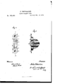
I. VETTER LEIN. sAsH FULLEST-CASE. No.18 5,369. Patented Dec-.'1Z,1876
PA'rn'r JOHN VETTERLEIN, OF PLAINFIELD, NEW JERSEY.
IMPROVEMENT IN SASH-PULLEV CASES.
Specification forming part of Letters Patent No. 185,369, dated December 12, 1876 application filed March 22, 1876.
To all whom it may concern:
Be it known that 1, JOHN VETTERLEIN, of Plainfield, in the county of Union and State of New Jersey, have invented an Improvement in Cases for Sheaves of Sashes, Doors, &e., of which the'following is a specification:
.It is usual in the manufacture of sash-pulleys, and sheaves for sliding doors, to employ a case with a flange all around the outer edge, and this flange is let into the surface ofv the wood of the window-frame or door so that the flange is flush. This operation involves considerable work, and itis difficult to do, as the body portion of the case is recessed into the wood-work.
In some instances the ends of the-sheavecase have been the segment of a cylinder, but the sides were flat; and in other cases the flange that is let into the surface of the wood has been composed of segments of circles, but the case itself has had flat sides.
I make use of a case having its exterior surface corrugated in the form of segments of cylinders fitting into a mortise formed by boring a row of holes. This construction lessens the work of fitting in the case, strengthens the case itself, and causes the strain upon the axis of the pulley to come upon the corrugated surfaces of the mortise contiguous to the axis, instead ofbeing taken upon the ends or flanges of the case.
In the drawing, Figure 1 is a front view of the case, and Fig. 2 is a side elevation of the same.
The sheave a is usually grooved around its periphery, and it is to be of greater or less size, according to the use to which the same is to be put, and the case is made of a proper size internally for receiving the same.
My improvement relates to the case b, made with an external surface composed of segments of cylinders c at opposite sides, so placed that they are adapted to enter mortises formed by holes bored in the wood, such holes intersecting, so that the interior of the opening made in the wood will be corrugations corresponding 'with' the corrugations upon the surface of the case. The attachingears 6 e are sections of a cylinder, with screws passing axially through the same.
To insert this case it is only necessary to lay ofl' upon a straight central line, 1 1, the distance corresponding to the cross-lines 2 3 4 5 6 7, and bore the two end holes 2 and 7 to a gaged depth for the reception of the flanges or ears c; then to bore the other holes of the depth necessary toreceive the pulley-case. Of course a bit of the proper diameter is used, and the holes cut into each other so the pulley-case can be inserted immediately that the holes have been bored. is not any occasion to use a chisel in making the opening for the pulley-case, and the corrugations on the side of the case, matching the corrugations in the bored mortise-hole, support the case reliably, and prevent undue strain coming upon the ears 6.
The metal of the case is to be largest at the outer portions of the corrugations, as shown, so that the case will wedge into the mortise as the same is driven in.
The inner portion of the case is preferably plain, so as not to require as much weight of metal as it would if the segmental corrugations extended the entire width of the case.
I claim as my invention- The sash-pulley case I), having sides formed entirely of segments of circles 0, combined with the faceplate, whose edges and ends are also parts of corresponding circles, as set forth.
Signed by me this 21st'day of March, A. D. 1876.
JOHN VETTERLEIN.
Witnesses:
Gem. '1. PINGKNEY, HAROLD SERRELL.
By this means there
Publications (1)
| Publication Number | Publication Date |
|---|---|
| US185369A true US185369A (en) | 1876-12-12 |
Family
ID=2254775
Family Applications (1)
| Application Number | Title | Priority Date | Filing Date |
|---|---|---|---|
| US185369D Expired - Lifetime US185369A (en) | Improvement in sash-pulley cases |
Country Status (1)
| Country | Link |
|---|---|
| US (1) | US185369A (en) |
-
0
- US US185369D patent/US185369A/en not_active Expired - Lifetime
Similar Documents
| Publication | Publication Date | Title |
|---|---|---|
| US1269311A (en) | Cremorne bolt. | |
| US185369A (en) | Improvement in sash-pulley cases | |
| US480299A (en) | voight | |
| US1265541A (en) | Window-sash. | |
| US127027A (en) | Improvement in sash-holders | |
| US306983A (en) | Window-sash pulley | |
| US1326937A (en) | Sash-lock | |
| US213006A (en) | Improvement in locks | |
| US1108873A (en) | Strike-plate. | |
| US462248A (en) | Sash-cord guide | |
| US182269A (en) | Improvement in hinges | |
| US263244A (en) | Warren h | |
| US250849A (en) | spaeks | |
| US1769915A (en) | Lock miter joint | |
| US1053900A (en) | Hinge-butt. | |
| US187708A (en) | Improvement in burglar-proof safe-doors | |
| US167338A (en) | Improvement in door-bolts | |
| US413971A (en) | Sash-cord guide | |
| US1185023A (en) | Split-hub lock. | |
| US1498228A (en) | Flange for bull-wheel shafts | |
| US197965A (en) | Improvement in locks for drawers | |
| US528892A (en) | Charles a | |
| US947168A (en) | Adjustable hinge. | |
| US5650A (en) | Bedstead-fastening | |
| US421905A (en) | Charles m |