US1853695A - Pneumatic improvement for solenoid hammers - Google Patents
Pneumatic improvement for solenoid hammers Download PDFInfo
- Publication number
- US1853695A US1853695A US431084A US43108430A US1853695A US 1853695 A US1853695 A US 1853695A US 431084 A US431084 A US 431084A US 43108430 A US43108430 A US 43108430A US 1853695 A US1853695 A US 1853695A
- Authority
- US
- United States
- Prior art keywords
- plunger
- drill
- solenoid
- cylinder
- opening
- Prior art date
- Legal status (The legal status is an assumption and is not a legal conclusion. Google has not performed a legal analysis and makes no representation as to the accuracy of the status listed.)
- Expired - Lifetime
Links
- 238000004804 winding Methods 0.000 description 9
- 238000005553 drilling Methods 0.000 description 8
- 238000004140 cleaning Methods 0.000 description 4
- 239000000428 dust Substances 0.000 description 4
- 230000004907 flux Effects 0.000 description 4
- 230000000717 retained effect Effects 0.000 description 4
- 239000007787 solid Substances 0.000 description 4
- 238000010276 construction Methods 0.000 description 2
- 239000011435 rock Substances 0.000 description 2
- 239000000126 substance Substances 0.000 description 2
- FBOUIAKEJMZPQG-AWNIVKPZSA-N (1E)-1-(2,4-dichlorophenyl)-4,4-dimethyl-2-(1,2,4-triazol-1-yl)pent-1-en-3-ol Chemical compound C1=NC=NN1/C(C(O)C(C)(C)C)=C/C1=CC=C(Cl)C=C1Cl FBOUIAKEJMZPQG-AWNIVKPZSA-N 0.000 description 1
- 208000036366 Sensation of pressure Diseases 0.000 description 1
- 230000006835 compression Effects 0.000 description 1
- 238000007906 compression Methods 0.000 description 1
- 239000004020 conductor Substances 0.000 description 1
- 238000006073 displacement reaction Methods 0.000 description 1
- 210000005069 ears Anatomy 0.000 description 1
- 229910052500 inorganic mineral Inorganic materials 0.000 description 1
- 239000000696 magnetic material Substances 0.000 description 1
- 239000000463 material Substances 0.000 description 1
- 239000011707 mineral Substances 0.000 description 1
- 239000002245 particle Substances 0.000 description 1
Images

Classifications
-
- E—FIXED CONSTRUCTIONS
- E21—EARTH DRILLING; MINING
- E21B—EARTH DRILLING, e.g. DEEP DRILLING; OBTAINING OIL, GAS, WATER, SOLUBLE OR MELTABLE MATERIALS OR A SLURRY OF MINERALS FROM WELLS
- E21B21/00—Methods or apparatus for flushing boreholes, e.g. by use of exhaust air from motor
- E21B21/01—Arrangements for handling drilling fluids or cuttings outside the borehole, e.g. mud boxes
- E21B21/011—Dust eliminating or dust removing while drilling
Definitions
- My invention relates to a pneumatic improvement for solenoid hammers, and is especially; adapted for. a solenoid hammer, Which is to be usedfor drilling rock, conccrsite,
- ' 1s invention has for its general object, the provision of a solenoid actuated hammer 'for drilling rock or other hard substances, wherein the dust, causedby the cutting or drilling operation, is automatically removedv from the cavity. 7 1
- Another object of this invention is the provision'of a device which is capable of being contained within asolenoid hammer or drill,
- a further object' is the provision of an improvement in a solenoid actuated hammer wherein the solenoidplunger may be used as an actuatorto force the dust, caused by the drilling operation, away from the drill.
- Another object is the pro vision of an improved solenoid hammer wherein a pneumatic pressure means is 10- cated within the hammer, in axial alignment Withthe tool. 7 r
- Anotherv object is: the provision of a pneumatic solenoid hammer, for drilling purposes, wherein the drill stem has a longitudinal, axial opening throughout its entire length, and wherein the. reciprocation of the solenoid plunger forcesair through the opening in the drill, but in which construction no valve is required'in the drill and wherein the base, or blow delivering portion, .of the plunger may be substantially solid.
- a further advantage isthe novel arrangement of attaching a drill to a solenoid hammer, whereby the drill is retained against eX cessivelongitudinal displacement and wherein novel means is used to prevent relativerotation between the drill and the hammer.
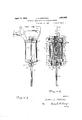
- Fig. 1 is a side elevation of a solenoid hammer embodying my'invention
- Fig. 2 is a front elevationof the hammerpartially broken away to. re-
- Fig. 3 is a horizontal sectionin a plane indicatedby the .lines 3 in 2;
- Fig. .4 is a horizontal section in a plane indicated by the lines 2-4 in Fig. 2;
- Fig. 5 is a horizontal section in a plane indicatedby the lines 5'5 in Fig. 2;
- Fig.6 is a horizontal section in a plane indicated by the lines 66 in Fig. 2;
- Fig. 7 is a horizontal, section in a plane indicated by the/lines 77 in Fig.2;
- Fig. 8 is a horizontalsection in a plane indicated by the lines 8-8 in Fig. 2. 4
- the plates 21 a-nd'22 haveou'twardly extending ears 23 through which suitable bolts 24 pass which bolts servetoretain the plates in av clamped position.
- a hand grip or handle 25 Integral with the upper plate 21 is a hand grip or handle 25, which in the embodiment shown houses; the switch 3, and-through which the electric conductors 1 and 2 enter the hammer.
- the plunger 6- reciprocates within the barrel 10 and is restrained from excessive upward movement by a plug 30, slidingly upper flangellof the barrel, thereby preventing; downward movement of thesleeve.
- the drill, or cutting tool is mounted in a centrally located circular opening 44 inthe lower clamping plate 22.
- the drill stem 45 is mounted for reciprocation in a cylindrical sleeve or mounting 46 which in turn is slidably mounted in the opening 44. It will be noted that relative rotation between the sleeve 46 and the drill stem, is prevented by a set screw 49, threaded into the sleeve and coacting with an external vertical slot 50, in the drill stem.
- theplate 60 has a square opening 62 adapted to receive a squared portion 63 of the drill' shank, thereby preventing relative rotation between the drill 45 and the hammer.
- the plate 60 is retained in position against a shoulder 64 of the drill by suitable compression springs 65 held in position on the studs 61 by wing nuts 66.
- the shoulder 64 of the drill shank bears against the lower surface of the sleeve 46 thereby resiliently retaining the sleeve in position against the flange 11 of the barrel 10.
- the drill shank 45 extends some distance above the sleeve 46, and normally receives the blow from the plunger 6, but if the drill is idle, (not in contact with the work), the blow will also be applied to the sleeve 46 and by reason of the resilient mounting the drill will be retained in position without damage to the parts.
- My invention contemplates the use of the plunger 6 for a piston or actuator to force a blast of air downwardt-hrough an axial opening extending the entire length of the drill 45.
- a longitudinal opening 71 which, at its lower portion, communicates with transverse openings 7 2 in the wall of said plunger.
- the lower portion of the plunger 6 has flattened pended, and partially because of the air pres sure set up in the chamber 7 3 and passageways 72.
- the plug 78 has an opening 80 which communicates with a chamber 81 above the plunger 6, hence on the upward movement of the plunger air is drawn into the lower chamber 7 3 between the stem 45 and the barrel 10.
- the plug 30' has "an axial opening 85 extending its entire length.
- the lower portion is enlarged as at 86 and forms a seat 87 against which a ball 88 is forcedby a suitable spring 89, retained in position within the plug by a threaded member90 having an axial opening 91.
- the plunger acts downwardly the ball 88 is withdrawn from the seat by a partial vacuum in the chamber 81 and air enters thechamber through an opening 92in the cap 35 but'when the plunger 6 acts upwardly, the ball 88 is urged against its seat 87, and the air, not able to escape upwardly, is forced downwardly into the chamber 73.
- a solenoid actuated hammer a hous-, ing, solenoid coil windings within the housing, a plunger adapted to be reciprocated by the flux produced by the windings, a guideway in which the plunger reciprocates and which is divided into two chambers by the plunger, a drill having an axial opening therethrough, a valve associated with the plunger and communicating with both chambers, a second valve member associated with one of said chambers, wherein the plunger on its stroke toward the other of said chambers imparts a sharp blow directly to the drill and forces air through the said axial opening in the drill. 7
- A'combined hole drilling and cleaning device comprising an openended non-magnetic cylinder, solenoid coil windings associated with the cylinder, a plunger within the cylinder, adapted to be reciprocated bythe magnetic flux produced by the windings, a drill mounted in the lower opening of the cylinder having an axial opening there- 'through, a valve in said plunger, a second valve mounted in the upper opening of the cylinder, one of said valves being normally seated and the other normally open, wherein the plunger on its down stroke directly contacts the drill and forces air out through the axial opening in the drill.
- a combined hole drilling device and compressor comprising an open ended nonmagnetic cylinder, solenoid coil windings as sociated with the cylinder, at plunger within the cylinder adapted to be reciprocated by the magnetic flux produced by the windings, a drill resiliently mountedin the lower opening of the cylinder having an axial opening therethrough, a valve in said plunger and normally open, a second valve mounted in the upper opening of the cylinder, means to normally the guideway and having an axial opening therethrough, the plunger also having an axial opening through one end portion thereof and a valve in said portion, the other end portion of said plunger being solid but provided with flattened surface portions forming passageways leading from the lower chamber of the cylinder to the level of the axial opening of said plunger and with radial openings comthe axial opening in the plunger,-the plunger valve being normally open, and said solid portion of the plunger reciprocating in alinement with the tool to strike directly upon the latter.
- a combined cutting and cleaning device comprising a solenoid actuated plunger, a cylindrical guideway for the plunger, a tool resiliently mounted for reciprocation in one end of the guideway, the tool having an axial opening therethrough, the plunger dividing the guideway into two chambers and mounted for delivering strokes directly upon the said tool, a valve mounted in the plunger and communicating with both chambers, the axial opening in the tool communicating with one of the chambers, a check valve mounted in the upper end of the guideway and communicating with the other chamber and means to prevent relative rotation between the tool and the guideway.
- a combined hole drilling and cleaning device comprising an open-ended non-magnetic cylinder, solenoid coil windings associated with the cylinder, a plunger within the cylinder adapted to be reciprocated by the magnetic flux produced by the windings and comprising an axial opening through its upper portion and a solid lower portion having flattened faces to provide lateral side passageways between the axial opening and the lower chamber of the cylinder, said plunger having radial openings connecting the passageways with said axial opening, a drill mounted in the lower opening of the cylinder having an axial opening therethrough, a valve in said axially open portion of the plunger, normally open, and a second valve mounted in the upper opening of the cylinder and normally seated.
- a combined cutting and cleaning device comprising a solenoid actuated plunger, a guidewayfor the plunger, a tool in one end of
Description
April 1932- s. E. MORTIMER 1,853,695
PNEUMATIC IMPROVEMENT FOR SOLENOID HAMMERS Filed Feb. 25, 1930 2 Sheets-Sheet 2 j "Flar'7 2 gwue'ntoz I 65 42 fiAMutL E. MORTIMER and other mineral or hard substances.
Patented Apr. 12, 1932 j" oNirsraTE's PATENT OFFICE SAMUEL: E. MoR'rIMER, on 'LORAIN, oHIo, ASSIGNOR' or TWENTY-Elvis onnnunnnnnrns To, CLARENCE M. GRTGGS, or LonAIN, OHIO rNEUMA'rIc IMPROVEMENT ron SOLENOID HAMMEBS Application filed February 25, 1930. Serial m5. 431,084.
My invention relates to a pneumatic improvement for solenoid hammers, and is especially; adapted for. a solenoid hammer, Which is to be usedfor drilling rock, conccrsite,
' 1s invention has for its general object, the provision of a solenoid actuated hammer 'for drilling rock or other hard substances, wherein the dust, causedby the cutting or drilling operation, is automatically removedv from the cavity. 7 1
Another object of this invention is the provision'of a device which is capable of being contained within asolenoid hammer or drill,
and which will pneumatically remove'the dust and small particles of material from beneath a drill. A further object'is the provision of an improvement in a solenoid actuated hammer wherein the solenoidplunger may be used as an actuatorto force the dust, caused by the drilling operation, away from the drill. Another object is the pro vision of an improved solenoid hammer wherein a pneumatic pressure means is 10- cated within the hammer, in axial alignment Withthe tool. 7 r
, Anotherv object is: the provision of a pneumatic solenoid hammer, for drilling purposes, wherein the drill stem has a longitudinal, axial opening throughout its entire length, and wherein the. reciprocation of the solenoid plunger forcesair through the opening in the drill, but in which construction no valve is required'in the drill and wherein the base, or blow delivering portion, .of the plunger may be substantially solid. A further advantage isthe novel arrangement of attaching a drill to a solenoid hammer, whereby the drill is retained against eX cessivelongitudinal displacement and wherein novel means is used to prevent relativerotation between the drill and the hammer. Other advantages and objects of this invention will become apparent from the following description relating to a preferred embodiment illustrated in the drawings, and
the essential and novel features will be sumi which bears against the outer face of the marized in the claims.
Referring to the drawings: Fig. 1 is a side elevation of a solenoid hammer embodying my'invention; Fig. 2is a front elevationof the hammerpartially broken away to. re-
veal the internal construction, and the angle of vision beingat right angles to that shown in-Fig. 1; Fig. 3 is a horizontal sectionin a plane indicatedby the .lines 3 in 2;
Fig. .4: is a horizontal section in a plane indicated by the lines 2-4 in Fig. 2; Fig. 5 is a horizontal section in a plane indicatedby the lines 5'5 in Fig. 2; Fig.6 is a horizontal section in a plane indicated by the lines 66 in Fig. 2; Fig. 7 is a horizontal, section in a plane indicated by the/lines 77 in Fig.2; Fig. 8 is a horizontalsection in a plane indicated by the lines 8-8 in Fig. 2. 4
R ferring again to the drawings and especially to Fig. 1, electric current supply lines, 1 and 2 lead to a suitable control switch 3 which communicates with coil windings!) of a solenoid arranged in the usual manner to cause a core member or plunger 6 tOreciprocate.. In the embodiment illustrated I prefer to employ a non-magneticcylinder or barrel 10 having at the opposite ends thereof outwardly extending flanges 11. Surrounding the barrel are suitable electromagnets, diagrammaticallyillustrated at l5. A cylindrical shell or housing 16, preferably of non-magnetic material, surrounds the electromagnets. The shell, barrel and electromagnetsv are clamped together by upperand lowerclamping blocks or plates 21 and 22 respectively. The plates 21 a-nd'22 haveou'twardly extending ears 23 through which suitable bolts 24 pass which bolts servetoretain the plates in av clamped position. Integral with the upper plate 21 is a hand grip or handle 25, which in the embodiment shown houses; the switch 3, and-through which the electric conductors 1 and 2 enter the hammer.
The plunger 6- reciprocates within the barrel 10 and is restrained from excessive upward movement by a plug 30, slidingly upper flangellof the barrel, thereby preventing; downward movement of thesleeve.
The drill, or cutting tool is mounted in a centrally located circular opening 44 inthe lower clamping plate 22. In the embodiment" shown, the drill stem 45 is mounted for reciprocation in a cylindrical sleeve or mounting 46 which in turn is slidably mounted in the opening 44. It will be noted that relative rotation between the sleeve 46 and the drill stem, is prevented by a set screw 49, threaded into the sleeve and coacting with an external vertical slot 50, in the drill stem.
A retaining plate mounted on studs 61, secured to the lower clamping plate 22, serves to retain the drill 45 in position relative to the hammer. In the embodiment illustrated in Figs. 1, 2 and 8, theplate 60 has a square opening 62 adapted to receive a squared portion 63 of the drill' shank, thereby preventing relative rotation between the drill 45 and the hammer. The plate 60 is retained in position against a shoulder 64 of the drill by suitable compression springs 65 held in position on the studs 61 by wing nuts 66. The shoulder 64 of the drill shank bears against the lower surface of the sleeve 46 thereby resiliently retaining the sleeve in position against the flange 11 of the barrel 10. It will be noted that the drill shank 45 extends some distance above the sleeve 46, and normally receives the blow from the plunger 6, but if the drill is idle, (not in contact with the work), the blow will also be applied to the sleeve 46 and by reason of the resilient mounting the drill will be retained in position without damage to the parts.
My invention contemplates the use of the plunger 6 for a piston or actuator to force a blast of air downwardt-hrough an axial opening extending the entire length of the drill 45. Extending partially through the plunger 6 is a longitudinal opening 71 which, at its lower portion, communicates with transverse openings 7 2 in the wall of said plunger. The lower portion of the plunger 6 has flattened pended, and partially because of the air pres sure set up in the chamber 7 3 and passageways 72. The plug 78 has an opening 80 which communicates with a chamber 81 above the plunger 6, hence on the upward movement of the plunger air is drawn into the lower chamber 7 3 between the stem 45 and the barrel 10.
To permit air to enter the chamber 81 on the downward movement of the plunger, and pre vent its escape on the upward movement of the plunger, I provide the plug 30 with a suitable passageway and check valve 88.
As illustrated, the plug 30' has "an axial opening 85 extending its entire length. The lower portion is enlarged as at 86 and forms a seat 87 against which a ball 88 is forcedby a suitable spring 89, retained in position within the plug by a threaded member90 having an axial opening 91.- When the plunger acts downwardly the ball 88 is withdrawn from the seat by a partial vacuum in the chamber 81 and air enters thechamber through an opening 92in the cap 35 but'when the plunger 6 acts upwardly, the ball 88 is urged against its seat 87, and the air, not able to escape upwardly, is forced downwardly into the chamber 73.
To prevent dirt and dust from entering the various passageways-I prefer to mount a fine wire mesh screen between the spring 34 and the end of cap 35, which screen effectively covers the opening 92 for the purpose described. 7
Having set forth the principles of my invention and described and illustrated a preferred embodiment thereof for practical use, what I claim and desire to secure by Letters Patent, is,
1. In a solenoid actuated hammer, a hous-, ing, solenoid coil windings within the housing, a plunger adapted to be reciprocated by the flux produced by the windings, a guideway in which the plunger reciprocates and which is divided into two chambers by the plunger, a drill having an axial opening therethrough, a valve associated with the plunger and communicating with both chambers, a second valve member associated with one of said chambers, wherein the plunger on its stroke toward the other of said chambers imparts a sharp blow directly to the drill and forces air through the said axial opening in the drill. 7
2. A'combined hole drilling and cleaning device, comprising an openended non-magnetic cylinder, solenoid coil windings associated with the cylinder, a plunger within the cylinder, adapted to be reciprocated bythe magnetic flux produced by the windings, a drill mounted in the lower opening of the cylinder having an axial opening there- 'through, a valve in said plunger, a second valve mounted in the upper opening of the cylinder, one of said valves being normally seated and the other normally open, wherein the plunger on its down stroke directly contacts the drill and forces air out through the axial opening in the drill.
3. A combined hole drilling device and compressor comprising an open ended nonmagnetic cylinder, solenoid coil windings as sociated with the cylinder, at plunger within the cylinder adapted to be reciprocated by the magnetic flux produced by the windings, a drill resiliently mountedin the lower opening of the cylinder having an axial opening therethrough, a valve in said plunger and normally open, a second valve mounted in the upper opening of the cylinder, means to normally the guideway and having an axial opening therethrough, the plunger also having an axial opening through one end portion thereof and a valve in said portion, the other end portion of said plunger being solid but provided with flattened surface portions forming passageways leading from the lower chamber of the cylinder to the level of the axial opening of said plunger and with radial openings comthe axial opening in the plunger,-the plunger valve being normally open, and said solid portion of the plunger reciprocating in alinement with the tool to strike directly upon the latter. In witness whereof, I have hereunto set my hand this eighteenth day of February, 1930. SAMUEL E. MORTIMER,
prevent movement of the last named valve in a downward direction and means to'permit sald valve to move upwardly.
4. A combined cutting and cleaning device comprising a solenoid actuated plunger, a cylindrical guideway for the plunger, a tool resiliently mounted for reciprocation in one end of the guideway, the tool having an axial opening therethrough, the plunger dividing the guideway into two chambers and mounted for delivering strokes directly upon the said tool, a valve mounted in the plunger and communicating with both chambers, the axial opening in the tool communicating with one of the chambers, a check valve mounted in the upper end of the guideway and communicating with the other chamber and means to prevent relative rotation between the tool and the guideway.
5. A combined hole drilling and cleaning device, comprising an open-ended non-magnetic cylinder, solenoid coil windings associated with the cylinder, a plunger within the cylinder adapted to be reciprocated by the magnetic flux produced by the windings and comprising an axial opening through its upper portion and a solid lower portion having flattened faces to provide lateral side passageways between the axial opening and the lower chamber of the cylinder, said plunger having radial openings connecting the passageways with said axial opening, a drill mounted in the lower opening of the cylinder having an axial opening therethrough, a valve in said axially open portion of the plunger, normally open, and a second valve mounted in the upper opening of the cylinder and normally seated.
6.. A combined cutting and cleaning device comprising a solenoid actuated plunger, a guidewayfor the plunger, a tool in one end of
Priority Applications (1)
| Application Number | Priority Date | Filing Date | Title |
|---|---|---|---|
| US431084A US1853695A (en) | 1930-02-25 | 1930-02-25 | Pneumatic improvement for solenoid hammers |
Applications Claiming Priority (1)
| Application Number | Priority Date | Filing Date | Title |
|---|---|---|---|
| US431084A US1853695A (en) | 1930-02-25 | 1930-02-25 | Pneumatic improvement for solenoid hammers |
Publications (1)
| Publication Number | Publication Date |
|---|---|
| US1853695A true US1853695A (en) | 1932-04-12 |
Family
ID=23710382
Family Applications (1)
| Application Number | Title | Priority Date | Filing Date |
|---|---|---|---|
| US431084A Expired - Lifetime US1853695A (en) | 1930-02-25 | 1930-02-25 | Pneumatic improvement for solenoid hammers |
Country Status (1)
| Country | Link |
|---|---|
| US (1) | US1853695A (en) |
Cited By (7)
| Publication number | Priority date | Publication date | Assignee | Title |
|---|---|---|---|---|
| US2441403A (en) * | 1945-07-05 | 1948-05-11 | Burr N Engle | Teeth setter for saws |
| US2441404A (en) * | 1946-06-18 | 1948-05-11 | Burr N Engle | Device for setting saw teeth |
| US2504399A (en) * | 1946-06-18 | 1950-04-18 | Burr N Engle | Automatic tooth setter for saws |
| US2700746A (en) * | 1954-01-11 | 1955-01-25 | Vang Alfred | Means for the conversion of stored electrical energy into mechanical energy |
| US4015671A (en) * | 1973-04-17 | 1977-04-05 | Vladimir Mikhailovich Borisov | Electric hammer |
| US4515303A (en) * | 1982-08-28 | 1985-05-07 | Robert Bosch Gmbh | Electric hammering apparatus with air-cushioned armature |
| FR2571294A1 (en) * | 1984-10-09 | 1986-04-11 | Bosch Gmbh Robert | ELECTROMAGNETIC SHIFTING APPARATUS COMPRISING A PNEUMATIC SHOCK ABSORBER |
-
1930
- 1930-02-25 US US431084A patent/US1853695A/en not_active Expired - Lifetime
Cited By (8)
| Publication number | Priority date | Publication date | Assignee | Title |
|---|---|---|---|---|
| US2441403A (en) * | 1945-07-05 | 1948-05-11 | Burr N Engle | Teeth setter for saws |
| US2441404A (en) * | 1946-06-18 | 1948-05-11 | Burr N Engle | Device for setting saw teeth |
| US2504399A (en) * | 1946-06-18 | 1950-04-18 | Burr N Engle | Automatic tooth setter for saws |
| US2700746A (en) * | 1954-01-11 | 1955-01-25 | Vang Alfred | Means for the conversion of stored electrical energy into mechanical energy |
| US4015671A (en) * | 1973-04-17 | 1977-04-05 | Vladimir Mikhailovich Borisov | Electric hammer |
| US4515303A (en) * | 1982-08-28 | 1985-05-07 | Robert Bosch Gmbh | Electric hammering apparatus with air-cushioned armature |
| FR2571294A1 (en) * | 1984-10-09 | 1986-04-11 | Bosch Gmbh Robert | ELECTROMAGNETIC SHIFTING APPARATUS COMPRISING A PNEUMATIC SHOCK ABSORBER |
| US4611742A (en) * | 1984-10-09 | 1986-09-16 | Robert Bosch Gmbh | Electromagnetically operated driving tool with air damper |
Similar Documents
| Publication | Publication Date | Title |
|---|---|---|
| US1853695A (en) | Pneumatic improvement for solenoid hammers | |
| US2427358A (en) | Pneumatically operated marking machine | |
| US2490302A (en) | Means for removing embedded material | |
| US2273095A (en) | Internal combustion hammer | |
| US2861778A (en) | Electromagnetic reciprocating hammer | |
| US3584776A (en) | Pneumatically actuated stapling tool | |
| US3356166A (en) | Percussive tool | |
| GB803020A (en) | Improvements in and relating to a drilling machine | |
| US2003843A (en) | Power press | |
| US2527757A (en) | Bushing for pneumatic hammers | |
| US1383432A (en) | Solenoid-operated valve and the like | |
| US2180034A (en) | Internal combustion hammer | |
| US2164970A (en) | Riveting tool | |
| US2248110A (en) | Electric hammer | |
| US1813513A (en) | Internal combustion hammer | |
| US896439A (en) | Valve. | |
| US2633085A (en) | Carburetor acceleration pump | |
| US2693767A (en) | Oil well pump plunger valve | |
| US1924545A (en) | Drop hammer | |
| US1847085A (en) | Percussive tool | |
| US1689410A (en) | Hydraulic footstock | |
| US2090031A (en) | Rock drill | |
| US1551989A (en) | Vacuum-power hammer | |
| CN219954402U (en) | Valve body structure of double-point oil separator | |
| GB1015719A (en) | Improvements in motor-driven hammers |