US1853678A - Method of and means for separating desired from undesired electric currents - Google Patents
Method of and means for separating desired from undesired electric currents Download PDFInfo
- Publication number
- US1853678A US1853678A US113896A US11389626A US1853678A US 1853678 A US1853678 A US 1853678A US 113896 A US113896 A US 113896A US 11389626 A US11389626 A US 11389626A US 1853678 A US1853678 A US 1853678A
- Authority
- US
- United States
- Prior art keywords
- currents
- current
- frequency
- fatigue
- instrument
- Prior art date
- Legal status (The legal status is an assumption and is not a legal conclusion. Google has not performed a legal analysis and makes no representation as to the accuracy of the status listed.)
- Expired - Lifetime
Links
- 238000000034 method Methods 0.000 title description 29
- 206010016256 fatigue Diseases 0.000 description 43
- 230000003321 amplification Effects 0.000 description 18
- 238000003199 nucleic acid amplification method Methods 0.000 description 18
- 230000000694 effects Effects 0.000 description 17
- 230000010355 oscillation Effects 0.000 description 15
- 230000008569 process Effects 0.000 description 15
- 230000003412 degenerative effect Effects 0.000 description 13
- 230000008929 regeneration Effects 0.000 description 13
- 238000011069 regeneration method Methods 0.000 description 13
- 230000009471 action Effects 0.000 description 6
- 239000002131 composite material Substances 0.000 description 5
- 230000001172 regenerating effect Effects 0.000 description 5
- 230000007850 degeneration Effects 0.000 description 4
- 238000000926 separation method Methods 0.000 description 4
- 241001425718 Vagrans egista Species 0.000 description 3
- 230000008030 elimination Effects 0.000 description 3
- 238000003379 elimination reaction Methods 0.000 description 3
- 230000000670 limiting effect Effects 0.000 description 3
- 230000003313 weakening effect Effects 0.000 description 3
- XEEYBQQBJWHFJM-UHFFFAOYSA-N Iron Chemical group [Fe] XEEYBQQBJWHFJM-UHFFFAOYSA-N 0.000 description 2
- 230000008878 coupling Effects 0.000 description 2
- 238000010168 coupling process Methods 0.000 description 2
- 238000005859 coupling reaction Methods 0.000 description 2
- 230000001788 irregular Effects 0.000 description 2
- 230000002035 prolonged effect Effects 0.000 description 2
- 230000000306 recurrent effect Effects 0.000 description 2
- 230000002441 reversible effect Effects 0.000 description 2
- 230000003068 static effect Effects 0.000 description 2
- 230000001629 suppression Effects 0.000 description 2
- 241001527902 Aratus Species 0.000 description 1
- 230000003190 augmentative effect Effects 0.000 description 1
- 230000008901 benefit Effects 0.000 description 1
- 238000010586 diagram Methods 0.000 description 1
- 238000009499 grossing Methods 0.000 description 1
- 230000006872 improvement Effects 0.000 description 1
- 230000036961 partial effect Effects 0.000 description 1
- 230000004962 physiological condition Effects 0.000 description 1
- 229920000136 polysorbate Polymers 0.000 description 1
- 230000008092 positive effect Effects 0.000 description 1
- 230000009467 reduction Effects 0.000 description 1
- 230000002829 reductive effect Effects 0.000 description 1
- 238000009877 rendering Methods 0.000 description 1
- 230000000979 retarding effect Effects 0.000 description 1
- 238000004904 shortening Methods 0.000 description 1
Images
Classifications
-
- H—ELECTRICITY
- H04—ELECTRIC COMMUNICATION TECHNIQUE
- H04B—TRANSMISSION
- H04B1/00—Details of transmission systems, not covered by a single one of groups H04B3/00 - H04B13/00; Details of transmission systems not characterised by the medium used for transmission
- H04B1/06—Receivers
- H04B1/10—Means associated with receiver for limiting or suppressing noise or interference
- H04B1/12—Neutralising, balancing, or compensation arrangements
Definitions
- This invention relates to certain improvementsin separating desired from undesired electric currents, and particularly in radio or line telegraphy and telephony and electrlcal picture reproduction, in which the deslred currents after partial separation from the undesired are utilized to cause a still further separation of the desired from the undesired currents by a process which may be called degeneration.
- An object of'my invention is toprovide means for increasing the fatigue effect in a circuit such as described in the parent specification hereinafter referred to for separating desired from undesired electric currents, and to hasten the degenerative process assoclated with this fatigue efiect.
- Another object is to prevent singing or self-disturbance of an amplifier system. 7
- a fatigue circuit that is, a circuit, for example, in which the source of current supply is capable of being exhausted by repeated or prolonged received impulses which cause the current supply to be consumed temporarily, this temporary exhaustion or fatigue being laterrestored.
- the fatiguable instrument is a transformer with magnetized -.moving iron core and is caused to become inoperative by fatigue of its action, allowing carrier current systems.
- the other instrument is providedwith current supply or energizing ;:II'1GE1I1S adapted to become temporarily ex- ;eha-ustedby repeated received impulses, which K drain the supply and may be referred to as L currents, and is hastened by the feedback by 'adegenerative process increased either by a feedback-system or by means of a succession of steps or cascade system.
- I provide two amplifying. instruments, which are connected in opposition each having an input'a-nd an: output circuit.
- the input circuit-of each instrument is fed from a common 'collector or line through current limiters, 'to prevent one of the instruments from be- 'CO1I111'lg:.1I10p8I'a.t1V6 from currents of-high amplitudeinstead ofcurrents of high frequency ':as will be hereinafter explained.
- One of the instruments is provided with a constant current supply energizing means, and maybe referred to for clarity as-the the fatigue instrument.
- a feed-back circuit is provided: between i the outputand input circuits.
- the :desired current iscaused'to be of a higher frequency: than the: disturbance cur- YBO rents which it is desired: to eliminate.
- the current supply or energizing means of the fatigue instrument is adjusted to supply just sufficient current to reproduce the .undersired. currents.
- Fig. 1 is a diagrammatic View of my complete system for separatm g desired from undesired electric currents and may be used to eliminate extraneous disturbances or self disturbance of an amplifier system.
- Figsp2, 3, 4, 5, 6, 7, 8 and 9 are diagrams illustrating graphically the method of separating desired from undesired currents.
- a receiving circuit is indicated at 1 which may be any source of received signals of high frequency such as a detector circuit for radio from which it is desired to separate desired from undesired currents, the latter being of a lower frequency than the former.
- Numeral 2 Fig. 1 may be the primary and secondary of a suitable transformer for transferring the received currents to the system.
- Numerals 3 and 5 are rectifiers with polarizing batteries land 6, arranged to short circuit any currents having a voltage greater than that of the polarizing batteries in a wellknown manner of vacuum tube current limiters.
- Numeral 7 shows the output coil of 'the current limiter and input coil of a full wave rectification system of which the valves 8 and 9 which may be any suitable rectifiers such as thermionic valves, are used to rectify both halves of the incoming alternating currents in the well-known manner of full wave rectification.
- 10 is the output coil of the full wave rectifying system which is common to the input circuits 11 and 12 of the two thermionic amplifiers 15 and 16 respectively.
- 1.3 and 1 1 are grid biasing batteries of the tubes 15 and 16 respectively.
- 17 is a variable source of alternating current preferably adjustable from 1,000 to 30,000 cycles and may conveniently be a small alternating current generator operated by a variable speed motor to vary the frequency between the desired limits for the lower frequencies or it may be a thermionic Valve generator adjustable for the higher frequencies.
- 18 is a suitable rectifier for currents from alternator .17 and may conveniently be a thermionic valve.
- Numeral 19 designates a variable condenser for storing a certain reserve supply of rectified current.
- 20 and '21 are respectively variable resistance and inductance for the purpose of retarding the flow of rectified current from condenser 19 and smoothing out the ripples from the generator.
- Numeral 22 is a'sec- 0nd condenser, also variable which momentarily stores a supply of smooth rectified current to act as the B Battery plate supply of vacuum tube 15 which is herein referred to asthe fatigue instrument, the entire rectifying system of the plate circuit constituting a variable filter B supply.
- Numeral 23 is the orthodox B battery of vacuum tube 16 which is known as the constant instrument.
- 24 and 25 are respectively the output circuits of Vacuum tubes 15 and 16 and are coupled to a split secondary coil 26 and 27 each half being wound differentially which in turn is connected to the final recording instrument or telephone 32 through a feed-back coil 33.
- the switch 31 serves to transfer the output currents'to the variable condenser shunted relay through the rectifier 28, for operat ing the mechanical instrument 29 such as a photographic cylinder, when desired.
- the coil 33 transfers impulses by means of the coupling coil 34 through the single wave rectifier 35 and a variable impedance 36 to another coupling coil 37, which coil transfers impulses back to the common input circuit of tubes 15 and 16 by means of coil 38.
- the coil 37 may be coupled to the input circuit of a complete second stage similar to the first in the well-known manner of cascade amplification.
- .my system operates in the following manner.
- the preferred signal is a modulated continuous wave.
- the reason for this is that regardless" of the number'of stray impulses present in the path of the incoming signal, there will always be more impulses transferred to the fatigueinstrument when the signal is present than when it is not, due to the mushing or heterodyning of the wave frequency of the strays by the continuous wave. This mushing sound or its effect is taken as the desired signal, and accompanies strength, by adjustment of the polarizing batteries as is customary in current limiters of the type shown. 7
- radio frequency amplifiers are employed before the constant and fatigue instruments as in .my original disclosure previously referred to, these radio "frequency amplifiers automatically act as current limiters in the well-known manner of radio frequency amplifiers, which fail to amplify radio frequency currents above a certain point on the plate current curve while amplifying to a high degree currents below this point.
- radio frequency amplifiers it is preferred to employ radio frequency amplifiers before the detector but it is not essential for the purposes of illustrating the operation of the system.
- the grid biasing batteries 13, 14 are adjusted to provide a negative bias on the grids of the vacuum tubes 15, 16 respectively, and are adjusted to reduce the plate current of the vacuum tubes 15 and 16 to practicallyzero.
- variable frequency supply 17 is adjusted to supply just suflicient filter current through valve 18 by adjusting the impedance and resistance as will maintain sufficient plate voltage for the operation of the tube 15 as an opposing or balancing tube to tube 16 for the average frequency of the strays.
- the self oscillation period-or the self oscillation frequency of the tube 16 is then adjusted to approximate the stray frequencies. Both tubes act alike for these frequencies and no effect is produced in the final output circuit.
- the self oscillation of the feed-back system is approximately 60
- the frequency of the alternator would be adjusted to slightly over60, say 75, and the impedance of the filter supply adjusted to barely balance the tube 15against tube 16.
- the effect is to drain the filter supply of tube 15.
- the current limiter may be dispensed with or adjusted to pass currents of the highest amplitude.
- the adjustment of the other apparatus for eliminating self oscillation being the same as for eliminating strays.
- the system may be made automatically free from self-disturbances such as howling, singing, etc., by providing a signal having a greater frequency than that produced by the self oscillation of the system.
- the system is used in radio telegraphy to receive undamped waves,.
- the re ceived signal may be made audible by the self singing of the system while the signal is present.
- the feed-backsystem should be sufficiently aperiodic or'adjusted to feed-back a harmonic or a higher frequency than that corresponding to its self oscillation frequency.
- the system is adjusted to sing or howl only at a frequency deter- 1 plished in the following manner.
- the grid 1 being adjusted to pass approximately Zero plate current, will, upon the arrival of an alternating current impulse, cause an increase in plate supply for half the value of this im pulse.
- the other half is not efiective, since it has a tendency to decrease the conductivity of the tube.
- the apparatus is capable of separating currents having a much smaller difference in'frequency, and this is made possible by reducing the time necessary to exhaust the fatigue instrument and augmenting the effect by regeneration.
- the regeneration in this instance having the effect of degeneration of the fatigue tube action in addition to regeneration of amplitude.
- Fig. 2a represents graphically a desired current of high frequency after having both half waves rectified and amplified by the con stant instrument of vacuum tube amplifier 16.- The current limiter being adjusted to just pass currents of its amplitude as shown by the slight flattening or clipping of the tip of each wave peak.
- Fig. 2 represents graphically the same signal as rectified limited and amplified by the vacuum tube amplifier 15.
- the wave train instead of being uniform and constant as in-Fig. 2a, shows a gradual falling off in amplitude to zero after the initial impulse, due tothe inability of the plate supplyof tube 15 to recover sufiiciently between waves to supply current for the next incoming wave.
- Fig. 20 illustrates the result of combining two wave trains a and b in opposition and shows a signal which is weak at the start and gradually becomes stronger until a maximum is reached.
- Fig. 2, a, b and 0, correspond in effect to Fig. 4, a, b and 0, of my original patent without regeneration, the chief difference being v that the effect herein described is produced with vacuum valves instead of transformers.
- Fig. 3, 0? illustrates the apparatus when used with the feed-back circuit shown in Fig. 1. It will be seen that the initial impulse of the wave train is similar to that of. Fig.
- Fig. 8 f shows the resultant, after opposing el and e, and it will be seen that the signal is not only of greater amplitude than in Fig. 2 a, but also of greater length, due tothe steep falling off of the wave trains inc.
- Fig. 4 9 illustrates a vagrant or stray impulse originating within the amplifying circuit itself, which ordinarily starts an amplifier system into'self oscillation.
- amplified impulses such as usually results from similar disturbances it will be noted that the original impulse is amplified to a maximum and then degenerates to a minimum which may be zero in a very short time. This is because both instruments 15 and 16 are so adjusted that while 15 will not support the amplification of a series of impulses such as a,. Fig. 2, it will support the amplification of a series of impulses which correspond to the natural period of the feedback circuit, hence completely balances it by opposition as shown at h, the resultant z, being zero.
- Fig. 5, 7' represents graphically a series of stray or vagrant impulses such as static arriving from without the system and collected by the collector or line 1 and passed through the various stages as in Fig. 2, and reproduced completely by amplifier 16.
- Fig. 5, 70 represents the same series as reproduced by amplifier 15 and also shows the wave train completely reproduced as in Fig.
- Irregular strays are ordinarily of such frequencies.
- Fig. 6, m represents a composite series of wave trains, of both desired and undesired currents occurring simultaneously and reproduced by amplifier 16 and is a composite of d, Fig. 3, 9, Fig. 4, and 1', Fig. 5. It will be noted that all frequencies and amplitudes are completely reproduced.
- Fig. 6, n represents the same series as reproduced by amplifier 15, in opposition to amplifier 16 and here the series is incomplete,
- Fig. 6, 0, represents the resultant after combining in opposition, m and n, and consists of a composite of the original series It will be noted that here again thefinal wave train is longer and of greater amplitude than when degeneration is not employed.
- Fig. 7 represents graphically for comparison aset ofcurves, in which the curvep representsthe outputof the system without degenerative amplification.
- Fig. 8 represents graphically anotherset of curves in which u represents the output of the system with degenerative amplification. It will be noted that wit degenerative amplification, Fig. 8, the output curve u, rises much more rapidly and reaches ahigher maximum.
- p u represents the out-. put curves of the system for desired currents.
- qo represent the output curves of the system for undesired currents.
- rw represent the fatigue curves of amplifier 16 or constant instrumentfor both. desired and undesired currents and showthat there is no falling off in current with time.
- sa1 represents the fatigue curves of amplifier 15 or the fatigue instrument previously referred to for undesired currents with and without degenerative amplification respect-ively for comparison.
- Curve .9 has a greater weakening of falling off of plate current sup ply of amplifier 15 than curve it, due to the rather broad dividing line between desired and undesired frequencies where degenerative amplification is not employed.
- Fatigue curves of amplifier 15 or the fatigue instrument for desired currents are represented at t and y respectively.
- curve y taken with degenerative. amplification is much steeper than curve t, which is taken without degenerative amplification and therefore 3 shows less opposition to the constant instrument and consequently a greater final output of the system.
- Fig. 9 represents graphically a resultant: composite wave train after the elimination of desiredfrom undesired currents in radio telephony and consists of a modulated continu: ous wave, the carrier wave frequency being, chosen as a convenient example as 500,000, the frequency after heterodyning as 20,000.. and the modulation frequency as 1,000.
- Su-- perimposed or combined with these frequen cies are a series of irregular waves or strays such as. shown in Fig. 5 7'. These irregularly shaped waves when not modulated by the transmitter produce the characteristic mushing. sound, which occurs whenever strays are heterodyned either by a transmitting continuous wave or by a local source of oscillations.
- the fatigue instrument 15 for radio 13618. phony is adjusted to supplyjust sufficient current toreproduce the modulation frequency or 1,000. cycles. It will then become inoperative for all but the initial impulses of the heterodyne frequency of20,000, allowing the constant instrument to reproduce in the output circuit, all composite heretodyne frequencies but not those which are notheterodyned or modulated such as. strays.
- strays When modulated by the transmitter, strays are divided up into groups or envelopes, which, having higher crests andlowertroughs than the mush, are distinguishable as desired signals, even though the mush is still a part of each envelope as shown in Fig. 9.
- the undesired or stray currents are eliminated from the troughs of modulated waves such as occur in radio telephony, but not from the crests or envelopes,
- the current limiter of one is adjusted to stop all amplitudes above the average voice amplitude, and the current limiter of the other is adjusted to shut out all amplitudes above the weakest desired currents that can be detected.
- ivacuum tubes to be operated in such manner that one causes an increase of current in the output circuit while the other causes a decrease of current, the effect being arranged to operate in conjunction in an output circuit,
- the present invention is not to be confused with this system, as both amplifiers herein mentioned operate similarly as regards current flow but operate in opposition and produce no effect in the output circuit funless the fatigue circuit is drained of supply.
- rality of instruments having a common input circuit to simultaneously receive said currents, one'of said instruments bemg sub ect to fatigue from currents of high frequency to render said instrument inoperative, the other instrument not being subject to fatigue, an output circuit for said instruments, means for indicating in the output circuit the difference in current strength in said instruments, and means to repeat the initial process by which the difference in current strength between the said instruments is obtained to cause a greater difference in current strength between said desired and undesired. currents.
- Means for separating desired from undesired electric currents comprising a plurality of instruments having a common input circuit to simultaneously receive said currents, one of said instruments adapted to receive a complete train of electric impulses and the other instrument adapted to receive an incomplete train of impulses, said instruments being connected in opposition, an output circuit associated with said instruments and means associated with said output circuit to cause a greater difference between said desired and undesired currents, said means being adapted for passing said desired current through a plurality of stages to cause separation by fatigue of desired from undesired currents.
- Means for separating desired from undesired electric currents comprising a plurality of instruments having a common in- "put circuit to simultaneously receive said currents, means for causing one of said instruments to be fatigued as to its currenttransmitting properties to different extents by currents of different frequencies, means for preventing the other of said instruments from being influenced by fatigue to the same degree as said first named instrument, an output circuit for said instruments and means associated with said output circuit adapted to render one of said instruments I still further fatigued by repeating the process which caused it to become initially fatigued and means to utilize desired currents from said instruments.
- Means for separating desired from undesired electric currents comprising a plurality of vacuum tubes having acommon input circuit to simultaneously receive said currents, means for causing one of said vac uum tubes to become fatigued as to its current transmitting properties to different extents by currents of diflerent frequencies, means forpreventing the other vacuum tube from being influenced by fatigue to the same degree as said first named vacuum tube, an output circuit for said vacuum tubes and means in said output circuit to indicate the difference in current strength in said vacuum tubes.
- Means for separating desired from undesired currents comprising a plurality of vacuum tubes connected in opposition and having a common input circuit to simultaneously receive said currents, means for transmittin through both of said vacuum tubes complete trains of impulses of predetermined frequencies, means for causing one of said vacuum tubes to transmit complete trains of impulses of said predetermined frequencies and incomplete trains of impulses only of other frequencies, an output circuit associated with said vacuum tubes and means in the output circuit to utilize current from said vacuum tubes.
- Means for separating desired from undesired electric currents comprising a plurality of vacuum tubes having a common input circuit to simultaneously receive said currents, means for causing one of said vacuum tubes to become fatigued as to its current-transmitting properties to different extents by currents of different frequencies, means for preventing the other of said vacuum tubes to become less influenced by fatigue than the first named vacuum tube by the said different frequency currents, an 0utput circuit for said vacuum tubes and means associated With said output circuit for rendering one of said vacuum tubes still further fatigued by repeating the process which caused it to become initially fatigued and means to utilize desired currents from said vacuum tubes.
Landscapes
- Engineering & Computer Science (AREA)
- Computer Networks & Wireless Communication (AREA)
- Signal Processing (AREA)
- Amplifiers (AREA)
Description
Aprll 12, 1932. G E 1,853,678
, METHOD OF AND MEANS FOR SEPARATING DESTRED FROM UNDESIRED ELECTRIC CURREN'PS Filed June 5, 1926 2 Sheets-Sheet 1 HHNHHH INVENTOR H c p/WM 4 April 12, 1932. E G GAGE 1,853,678
METHOD OF AND MEANS FOR SEPARATING DESIRED FROM UNDESIRED ELECTRIC CURRENTS Filed June 1926 2 Sheets-Sheet 2 TIME IN sscoubsvvv TOME IN SECON D5 INVENTOR Patented Apr. 12, 1932 UNITED STATES EDWARD PATENT OFFICE G. GAGE, OF BROOKLYN, NEW YORK, ASSIGNOR TO RADIO CORPORATION OF AMERICA, 0]? NEW YORK, N. Y., A CORPORATION OF DELAWARE METHOD or AND MEANS FOR SEPARATING DESIRED FROM UNDESIRED ELECTRIC.
. oURnENTs Application filed June 5,
This invention relates to certain improvementsin separating desired from undesired electric currents, and particularly in radio or line telegraphy and telephony and electrlcal picture reproduction, in which the deslred currents after partial separation from the undesired are utilized to cause a still further separation of the desired from the undesired currents by a process which may be called degeneration.
An object of'my invention is toprovide means for increasing the fatigue effect in a circuit such as described in the parent specification hereinafter referred to for separating desired from undesired electric currents, and to hasten the degenerative process assoclated with this fatigue efiect.
Another object is to prevent singing or self-disturbance of an amplifier system. 7
Other and ancillary objects will hereinafter appear.
In carrying out my invention I utilize what may be called a fatigue circuit, that is, a circuit, for example, in which the source of current supply is capable of being exhausted by repeated or prolonged received impulses which cause the current supply to be consumed temporarily, this temporary exhaustion or fatigue being laterrestored.
I then enhance this efiect by amplification and regeneration. Y
' The general characteristics of such a fatigue circuit are set forth in a patent granted to me August 18, 1925, No. 1,550,023.
While I'am aware that the term fatigue is most commonly used to indicate a physiological condition, it is chosen herein as in my original patent as being the term which most clearly describes the operation of the circuit, and is one of the simplest illustra tions of the principle involved. In all cases one instrument may be said to be exhausted or tired out by repeated impulses due to the fact that it cannot recuperate fast enough t3 operate for impulses which arrive too rapi ly.
In my original patent the fatiguable instrument is a transformer with magnetized -.moving iron core and is caused to become inoperative by fatigue of its action, allowing carrier current systems.
1926. Serial nmiiasss.
an opposed transformer of indefatiguable i type and consequently not subject to fatigue,
negative process or process ofwearing down or breaking down instead of building up theamplitude of impulses in a circuit.
I Accordingly,'I make use of this negative principle to produce a positive action, that is, I again cause the apparatus by opposing it to one with a positivecharacteristic, such as the well-known regenerative circuit, to function in such a manner that the algebraic sum of the two actions will be zero for certain frequencies and have a positive value for frequencies above a pre-determined value.
This allows the'system to separate desired from undesired currents when they are but slightly different in frequency. I
One of the uses to which such a system. may be put is the elimination of strays or static in radio receiving systems or the elimination of disturbances. in wire systems such as in telephony, telegraphy or electrical picture reproduction either in ordinary circuits or in Another use. for the system may befound in vacuum tube amplifiers to provide a strong feed-back for desired currents without selfoscillation of the system. This prevents singing or howling either electrically or acoustically and enormously increasesthe strength of the desired signal. 7 i
A number of thesefatigue circuits may be connected in cascade to increase signal strength and to hasten the degenerative process. I V
' Other'uses of the system will be apparent to those skilledin the art. a
' In place of the transformers with moving iron cores described in my original patent,
constantinstrument. The other instrument .cis providedwith current supply or energizing ;:II'1GE1I1S adapted to become temporarily ex- ;eha-ustedby repeated received impulses, which K drain the supply and may be referred to as L currents, and is hastened by the feedback by 'adegenerative process increased either by a feedback-system or by means of a succession of steps or cascade system.
In carrying out my invention informs illustrated in the accompanying drawings, I provide two amplifying. instruments, which are connected in opposition each having an input'a-nd an: output circuit. The input circuit-of each instrument is fed from a common 'collector or line through current limiters, 'to prevent one of the instruments from be- 'CO1I111'lg:.1I10p8I'a.t1V6 from currents of-high amplitudeinstead ofcurrents of high frequency ':as will be hereinafter explained.
One of the instruments is provided with a constant current supply energizing means, and maybe referred to for clarity as-the the fatigue instrument.
I One instrument is adjusted to reproduce only currents below a certain frequency, by
limiting the amount of supply current or certain time forthe functioning ofthe instrument. The other instrument is adjusted to reproduce all= frequencies.
energizing means whichit can deliver in a Both instruments will reproduce currents of a frequency belowa pre-determined value which may be-received'bythe collector or =line-and-as they .are in opposition these currents will be cancelled out.
. A feed-back circuit. is provided: between i the outputand input circuits.
When acurrent is-received, having a fre quency above the; pre-determined frequency which the limited current supply or fatigue instrument -can P reproduce, this instrument becomes gradually inoperative until the cur- ;rent supply-is exhausted or has fallen to an inoperative value.
.The .speed with which this effect takes place depends upon 1 the difl'erence in 'frequency betweenxthe desiredand undesired amplification.
The :desired current iscaused'to be of a higher frequency: than the: disturbance cur- YBO rents which it is desired: to eliminate.
The current supply or energizing means of the fatigue instrument is adjusted to supply just sufficient current to reproduce the .undersired. currents.
.It' follows then, that .upon the-arrival of a or final output circuit may be caused to be of much greater amplitude by amplification through regeneration. These amplified cur rents in turn, being fed back into the lnput circuits and hence to each instrument cause a-- still greater drain on the fatigue instrument current supply at each recurrent cycle of regeneration, thereby further weakening its operation. This weakened operation allows current of still greater amplitude to be supplied without opposition by the constant instrumentand passed to the recorder.
This action continues as long as the desired signal is present until a stable condition of the fatigue instrument is reached,-
with the filtersupply greatly weakened. This weakened condition of the instrument varies directly with the incoming frequency and as the weakening of the fatigue instrument allows the constant instrument to operate at" full power, it may be said that the output energy of the system increases directly as the difference between frequencies of desired and undesired currents.
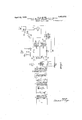
Reference is to be had to the accompanying drawings forming part hereof, wherein Fig. 1 is a diagrammatic View of my complete system for separatm g desired from undesired electric currents and may be used to eliminate extraneous disturbances or self disturbance of an amplifier system.
Figsp2, 3, 4, 5, 6, 7, 8 and 9 are diagrams illustrating graphically the method of separating desired from undesired currents.
A receiving circuit is indicated at 1 which may be any source of received signals of high frequency such as a detector circuit for radio from which it is desired to separate desired from undesired currents, the latter being of a lower frequency than the former.
Numeral 2 Fig. 1 may be the primary and secondary of a suitable transformer for transferring the received currents to the system. Numerals 3 and 5 are rectifiers with polarizing batteries land 6, arranged to short circuit any currents having a voltage greater than that of the polarizing batteries in a wellknown manner of vacuum tube current limiters. Numeral 7 shows the output coil of 'the current limiter and input coil of a full wave rectification system of which the valves 8 and 9 which may be any suitable rectifiers such as thermionic valves, are used to rectify both halves of the incoming alternating currents in the well-known manner of full wave rectification. 10 is the output coil of the full wave rectifying system which is common to the input circuits 11 and 12 of the two thermionic amplifiers 15 and 16 respectively. 1.3 and 1 1 are grid biasing batteries of the tubes 15 and 16 respectively. 17 is a variable source of alternating current preferably adjustable from 1,000 to 30,000 cycles and may conveniently be a small alternating current generator operated by a variable speed motor to vary the frequency between the desired limits for the lower frequencies or it may be a thermionic Valve generator adjustable for the higher frequencies. 18 is a suitable rectifier for currents from alternator .17 and may conveniently be a thermionic valve. Numeral 19 designates a variable condenser for storing a certain reserve supply of rectified current. 20 and '21 are respectively variable resistance and inductance for the purpose of retarding the flow of rectified current from condenser 19 and smoothing out the ripples from the generator. Numeral 22 is a'sec- 0nd condenser, also variable which momentarily stores a supply of smooth rectified current to act as the B Battery plate supply of vacuum tube 15 which is herein referred to asthe fatigue instrument, the entire rectifying system of the plate circuit constituting a variable filter B supply. Numeral 23 is the orthodox B battery of vacuum tube 16 which is known as the constant instrument. 24 and 25 are respectively the output circuits of Vacuum tubes 15 and 16 and are coupled to a split secondary coil 26 and 27 each half being wound differentially which in turn is connected to the final recording instrument or telephone 32 through a feed-back coil 33.
The switch 31 serves to transfer the output currents'to the variable condenser shunted relay through the rectifier 28, for operat ing the mechanical instrument 29 such as a photographic cylinder, when desired. The coil 33 transfers impulses by means of the coupling coil 34 through the single wave rectifier 35 and a variable impedance 36 to another coupling coil 37, which coil transfers impulses back to the common input circuit of tubes 15 and 16 by means of coil 38. Instead of feeding back through coil 37-38 the coil 37 may be coupled to the input circuit of a complete second stage similar to the first in the well-known manner of cascade amplification.
Vhen used to eliminate strays in radio telegraphy or electrical picture reproduction,
.my system operates in the following manner.
I The preferred signal isa modulated continuous wave. The reason for this is that regardless" of the number'of stray impulses present in the path of the incoming signal, there will always be more impulses transferred to the fatigueinstrument when the signal is present than when it is not, due to the mushing or heterodyning of the wave frequency of the strays by the continuous wave. This mushing sound or its effect is taken as the desired signal, and accompanies strength, by adjustment of the polarizing batteries as is customary in current limiters of the type shown. 7
lVhere radio frequency amplifiers are employed before the constant and fatigue instruments as in .my original disclosure previously referred to, these radio "frequency amplifiers automatically act as current limiters in the well-known manner of radio frequency amplifiers, which fail to amplify radio frequency currents above a certain point on the plate current curve while amplifying to a high degree currents below this point.
It is preferred to employ radio frequency amplifiers before the detector but it is not essential for the purposes of illustrating the operation of the system.
The grid biasing batteries 13, 14 are adjusted to provide a negative bias on the grids of the vacuum tubes 15, 16 respectively, and are adjusted to reduce the plate current of the vacuum tubes 15 and 16 to practicallyzero.
The variable frequency supply 17 is adjusted to supply just suflicient filter current through valve 18 by adjusting the impedance and resistance as will maintain sufficient plate voltage for the operation of the tube 15 as an opposing or balancing tube to tube 16 for the average frequency of the strays. The self oscillation period-or the self oscillation frequency of the tube 16 is then adjusted to approximate the stray frequencies. Both tubes act alike for these frequencies and no effect is produced in the final output circuit.
7 As an example, where the average frequency of strays is 50, the self oscillation of the feed-back system is approximately 60,
and the signal frequency 240, the frequency of the alternator would be adjusted to slightly over60, say 75, and the impedance of the filter supply adjusted to barely balance the tube 15against tube 16.
It is, of course, apparent that the greater the difference between the self oscillation frequency and the signal frequency, the less effective the feed-back circuit becomes, due to its reluctance to pass currents greatly outside its natural frequency. It is for this reason desirous not to raise the signal fresought.
difference between signal and stray the more quency too high when great regeneration is On the other hand, the greater the having the same effective voltage as the biasing or C batteries is received, the efiect will be to remove this negative bias, and cause the plate circuit to become conductive with the effect of increasing the plate current of both tubes. If the rectified current is momentary such as a stray click, both tubes act alike, and being in opposition no energy is passed to the output clrcuit. If, on the other hand this rectified current persists, as
in the case of a desired signal of higher fre quency than theundesired, the effect is to drain the filter supply of tube 15.
As these impulses arrive faster than the generator 17 can supply sufiicient effective voltage for the operation of the tube 15, the ability of this tube to oppose tube 16 is lost,
and with every recurrent cycle, its action becomes weaker through regeneration, which by amplification causes greater conductivity of the plate circuit of the fatigue instrument, hence more rapid exhaustion of its current supply and a hastening of the degenerative process, while the tube 16 continues to oper ate at full strength.
It can therefore be seen with only a very slight difference in frequency between signal and stray, if the signal is suficiently prolonged, it is bound to overcome the tube 15 and register in the final circuit as a. desired current.
The fact that the final currents consist of mixed frequencies is of no disadvantage because in telegraphy or picture reproduction only the marking and spacing are of importance, and in radio telephony, the frequency within modulating envelope may be raised beyond the upper range of audibility by super-heterodyning.
Then employed simply as a balanced amplifier system, in conjunction with a radio receiver, the current limiter may be dispensed with or adjusted to pass currents of the highest amplitude. The adjustment of the other apparatus for eliminating self oscillation being the same as for eliminating strays.
The system may be made automatically free from self-disturbances such as howling, singing, etc., by providing a signal having a greater frequency than that produced by the self oscillation of the system.
There the system is used in radio telegraphy to receive undamped waves,.the re ceived signal may be made audible by the self singing of the system while the signal is present.
When adjusted as described itwill be seen that an initial impulse imparted to the input system which would ordinarily cause the amplifier system to howl or sing, may be immediately eliminated by opposition before it can be regenerated, by adjusting the current supply of the fatigue instrument to supply just enough current for it to be able to oppose the constant instrument for self oscillation. A received signal of a higher frequency and proper length, will then cause the fatigue instrument to become inoperative by draining its current supply and wearing down its opposition, thereby allowing the constant instrument to deliver its full out put with regenerative amplification to the final or recording circuit.
It is to be understood that the feed-backsystem should be sufficiently aperiodic or'adjusted to feed-back a harmonic or a higher frequency than that corresponding to its self oscillation frequency. The system is adjusted to sing or howl only at a frequency deter- 1 plished in the following manner. The grid 1 being adjusted to pass approximately Zero plate current, will, upon the arrival of an alternating current impulse, cause an increase in plate supply for half the value of this im pulse. The other half is not efiective, since it has a tendency to decrease the conductivity of the tube.
By employing full wave rectification in the input circuit of both tubes for increasing plate current for the reception of desired signals from the collector, and only half wave effective rectification for the regenerative input, it is obvious that the whole wave rectification irrespective of frequency will exhaust the filter supply circuit of tube 15 more rapidly than the half wave rectified regenerative currents due to self oscillation because the frequency of the signal or desired current is always doubled while the self oscillation or undesired are not.
It is therefore possible to adjust the tube 15 to oppose tube 16 for the frequency of self oscillation but making it possible to render tube 15 inoperative by a received current lated, distorting a single envelope by mixing strays and signals within it, as illustrated in Figure 9 will not have a disturbing effect on the reproduction provided the intervals between modulation envelopes are silent in radio telephony and between characters when the apparatus is used for telegraphy or electrical picture reproduction.
The advantage of my improvement is in the reduction of time required to exhaust the fatigue instrument. In my original apparatus as described in U. S. Patent No. 1,550,023, the difference between desired and undesired currents is comparatively great as tofrequency, and the ap aratus is designed requencies of that for the separation of order.
In my present invention, the apparatus is capable of separating currents having a much smaller difference in'frequency, and this is made possible by reducing the time necessary to exhaust the fatigue instrument and augmenting the effect by regeneration. The regeneration in this instance having the effect of degeneration of the fatigue tube action in addition to regeneration of amplitude. To illustrate more clearly, assuming a slight difference in frequency to exist between desired and undesired currents received in a common input circuit by both tubes. generation it would take a definite time to exhaust the filter supply of the fatigue tube 15, or if the difference was so slight that it could not be exhausted a definite time would be required to reduce the supply to a point where it would be able to supply constant voltage, this voltage of necessity being lower than that of the current supply of tube 16.
With degenerative amplification, however, this time is greatly reduced, because the greater the amplitude due to regeneration through tube 16 the more rapidly will the filter supply of tube 15 be exhausted, and the more rapidly this tube is exhausted the greater will be the energy available through tube 16 for further degeneration of tube 15 Therefore, while the initial difference be tween the two frequencies causes only a slight effect requiring a comparatively long time to register, and causing a comparatively small indication, when the fatigue tube becomes constant, it is possible by degenerative amplification to accomplish a double effect in the final output circuit, namely, increase of amplitude and shortening of time limit.
Without re- These effects take place only for the duration of the predominating highest incoming frequency. For this reason, the apparatus is very stable for differences in frequency which are momentary, such as vagrant impulses, and will not pick up a very slight difference in frequency and augment it unless this difference persists.
I This is very necessary when strays such as grinders are being eliminated.
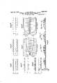
In Figs; 2, 3, 4, 5, 6, 7, 8, and 9 I have illustrated graphically the effect of the apparatus described in receiving currents of high and low frequency.
Fig. 2a represents graphically a desired current of high frequency after having both half waves rectified and amplified by the con stant instrument of vacuum tube amplifier 16.- The current limiter being adjusted to just pass currents of its amplitude as shown by the slight flattening or clipping of the tip of each wave peak.
Fig. 2?) represents graphically the same signal as rectified limited and amplified by the vacuum tube amplifier 15.
. It will be seen that in this case, the wave train, instead of being uniform and constant as in-Fig. 2a, shows a gradual falling off in amplitude to zero after the initial impulse, due tothe inability of the plate supplyof tube 15 to recover sufiiciently between waves to supply current for the next incoming wave.
Fig. 20 illustrates the result of combining two wave trains a and b in opposition and shows a signal which is weak at the start and gradually becomes stronger until a maximum is reached. f
Fig. 2, a, b and 0, correspond in effect to Fig. 4, a, b and 0, of my original patent without regeneration, the chief difference being v that the effect herein described is produced with vacuum valves instead of transformers.
Fig. 3, 0?, illustrates the apparatus when used with the feed-back circuit shown in Fig. 1. It will be seen that the initial impulse of the wave train is similar to that of. Fig.
2 a, but isfollowed by an impulse of greater amplitude due to amplification by regenera- I tion. Every alternate impulse of the train is amplified by this means. In Fig. 3 e, the
initial impulse, followed by an amplified impulse is all that appears, because the current supply of the vacuum tube 15 has become' rapidly exhausted by the degenerative process.
Fig. 8 f shows the resultant, after opposing el and e, and it will be seen that the signal is not only of greater amplitude than in Fig. 2 a, but also of greater length, due tothe steep falling off of the wave trains inc. Fig. 4 9 illustrates a vagrant or stray impulse originating within the amplifying circuit itself, which ordinarily starts an amplifier system into'self oscillation.
Instead of a continuous series of greatly minus the initial impulses.
amplified impulses, such as usually results from similar disturbances it will be noted that the original impulse is amplified to a maximum and then degenerates to a minimum which may be zero in a very short time. This is because both instruments 15 and 16 are so adjusted that while 15 will not support the amplification of a series of impulses such as a,. Fig. 2, it will support the amplification of a series of impulses which correspond to the natural period of the feedback circuit, hence completely balances it by opposition as shown at h, the resultant z, being zero.
Only alternate impulses appear in the plate circuits of instruments 15 and 16 because of the single rectification eflect of the rectifier 35 in the feed-back circuit. These are shown graphically as half waves for purposes of clarity in illustrating but actually they are alternations with idle spaces between each cycle. Theentire wave trains, g and h, Fig. 4, appear in an envelope as a click in a telephone receiver or loud speaker. instead. of a continuous singing or howling, because of the rapid stablization of the two amplifiers 15 and 16 by opposition.
Fig. 5, 7', represents graphically a series of stray or vagrant impulses such as static arriving from without the system and collected by the collector or line 1 and passed through the various stages as in Fig. 2, and reproduced completely by amplifier 16.
Fig. 5, 70, represents the same series as reproduced by amplifier 15 and also shows the wave train completely reproduced as in Fig.
4, h, and for the same reason, namely that the plate current supply of amplifier 15 is ad justed to supply sufiicient current for undeslred or currents below the frequency of the,
desired. Irregular strays are ordinarily of such frequencies.
Fig. 6, m, represents a composite series of wave trains, of both desired and undesired currents occurring simultaneously and reproduced by amplifier 16 and is a composite of d, Fig. 3, 9, Fig. 4, and 1', Fig. 5. It will be noted that all frequencies and amplitudes are completely reproduced.
Fig. 6, n, represents the same series as reproduced by amplifier 15, in opposition to amplifier 16 and here the series is incomplete,
only the initial impulse amplified by regen eration being shown, fter which the amplifier 15 becomes inoperative and does not re- .cuperate until a break appears in the signal wav'e train.
Fig. 6, 0, represents the resultant after combining in opposition, m and n, and consists of a composite of the original series It will be noted that here again thefinal wave train is longer and of greater amplitude than when degeneration is not employed.
Fig. 7 represents graphically for comparison aset ofcurves, in which the curvep representsthe outputof the system without degenerative amplification.
Fig. 8 represents graphically anotherset of curves in which u represents the output of the system with degenerative amplification. It will be noted that wit degenerative amplification, Fig. 8, the output curve u, rises much more rapidly and reaches ahigher maximum.
In Figs. 7 and 8, p u, represents the out-. put curves of the system for desired currents. qo represent the output curves of the system for undesired currents.
rw represent the fatigue curves of amplifier 16 or constant instrumentfor both. desired and undesired currents and showthat there is no falling off in current with time.
sa1 represents the fatigue curves of amplifier 15 or the fatigue instrument previously referred to for undesired currents with and without degenerative amplification respect-ively for comparison.
Curve .9, it will be noted, has a greater weakening of falling off of plate current sup ply of amplifier 15 than curve it, due to the rather broad dividing line between desired and undesired frequencies where degenerative amplification is not employed.
Fatigue curves of amplifier 15 or the fatigue instrument for desired currents are represented at t and y respectively. Here it will a be noted, curve y, taken with degenerative. amplification is much steeper than curve t, which is taken without degenerative amplification and therefore 3 shows less opposition to the constant instrument and consequently a greater final output of the system.
Fig. 9 represents graphically a resultant: composite wave train after the elimination of desiredfrom undesired currents in radio telephony and consists of a modulated continu: ous wave, the carrier wave frequency being, chosen as a convenient example as 500,000, the frequency after heterodyning as 20,000.. and the modulation frequency as 1,000. Su-- perimposed or combined with these frequen cies are a series of irregular waves or strays such as. shown in Fig. 5 7'. These irregularly shaped waves when not modulated by the transmitter produce the characteristic mushing. sound, which occurs whenever strays are heterodyned either by a transmitting continuous wave or by a local source of oscillations.
The fatigue instrument 15 for radio 13618. phony is adjusted to supplyjust sufficient current toreproduce the modulation frequency or 1,000. cycles. It will then become inoperative for all but the initial impulses of the heterodyne frequency of20,000, allowing the constant instrument to reproduce in the output circuit, all composite heretodyne frequencies but not those which are notheterodyned or modulated such as. strays.
The reasonfor this selectionis, due .to-the fact that the fatigue instrument has su'fii-,
cient time to recover between modulation envelopes but not between crests of the waves within the individual envelope.
When modulated by the transmitter, strays are divided up into groups or envelopes, which, having higher crests andlowertroughs than the mush, are distinguishable as desired signals, even though the mush is still a part of each envelope as shown in Fig. 9.
In other words the undesired or stray currents are eliminated from the troughs of modulated waves such as occur in radio telephony, but not from the crests or envelopes,
As the general shape of the envelope is unchanged however, in radio telephony, and the spaces between them clear, the modulatlon remains clear.
In radio telegraphy or electrical picture Q reproduction the fact that the spaces between the current limiter may be adjusted to eliminate current amplitudes above this maximum, but in radio telephony where this maximum is constantly varying, it is preferable to provide two complete sets of apparatus, their output circuits connected to operate in conjunction.
.The current limiter of one is adjusted to stop all amplitudes above the average voice amplitude, and the current limiter of the other is adjusted to shut out all amplitudes above the weakest desired currents that can be detected. By variously proportioning the combined amplified results of the two systems, an average may be found which has the least distortion.
The circuits and apparatus for accomplishing this result is shown in my pending application Method of and means for separating desired from undesired electric currents,
filed February 6, 192%, Serial No. 690,947,
ivacuum tubes to be operated in such manner that one causes an increase of current in the output circuit while the other causes a decrease of current, the effect being arranged to operate in conjunction in an output circuit, The present invention is not to be confused with this system, as both amplifiers herein mentioned operate similarly as regards current flow but operate in opposition and produce no effect in the output circuit funless the fatigue circuit is drained of supply.
In radio telegraphy, where the sig I am also aware that what is. known as a reverse feed-back is often employed as a means of preventing self disturbances in an amplifier system, and the present method of preventing self oscillation is not to be confused with such a system, because the feedback herein isnot reverse on negative inoperation as regards direction of current flow.v
On the contrary, it is positive, as in the ordinary regenerative circuit, the means for preventing self disturbance or self oscillation depending upon the action of the fatigue circuit.
Having thus described my invention, I claim 1. Means for separating desired from undesired electric'currents, comprising a PIU'.
rality of instruments having a common input circuit to simultaneously receive said currents, one'of said instruments bemg sub ect to fatigue from currents of high frequency to render said instrument inoperative, the other instrument not being subject to fatigue, an output circuit for said instruments, means for indicating in the output circuit the difference in current strength in said instruments, and means to repeat the initial process by which the difference in current strength between the said instruments is obtained to cause a greater difference in current strength between said desired and undesired. currents.
2. Means for separating desired from undesired electric currents comprising a plurality of instruments having a common input circuit to simultaneously receive said currents, one of said instruments adapted to receive a complete train of electric impulses and the other instrument adapted to receive an incomplete train of impulses, said instruments being connected in opposition, an output circuit associated with said instruments and means associated with said output circuit to cause a greater difference between said desired and undesired currents, said means being adapted for passing said desired current through a plurality of stages to cause separation by fatigue of desired from undesired currents.
3. The method of separating desired from undesired electric currents consisting in amplifying said currents causing a portion of one of said currents to be suppressed by fatigue, placing said currents in opposition 'to' cancel the initial impulse of the current, causing the remaining current to further suppress one of said currents by repeating the process by which said'first portion of one of said currents was suppressed, and utilizing the remaining current.
4. The method of separating desired from undesired electric currents consisting in receiving and amplifying interrupted currents, causing all except the initial impulse of one of said amplified interrupted currents to be suppressed by fatigue, placing said interrupted currents in opposition to cancel the initial impulse ofthe currents, causing said suppressed impulses to be restored between interruptions, utilizing the remaining currents to cause a further suppression of first said suppressed currents byrepeating the process by which said first currents Were suppressed, and utilizing the remaining currents as desired currents.
5. The method of separating desired from undesired electric currents consisting in receiving and amplifying said currents in the form of a complete train of electrical impulses, receiving and amplifying said currents in the form of an incomplete train of electrical impulses, opposing said complete and incomplete trains of impulses to cancel undesired currents, causing the remaining currents to render said incomplete train of electrical impulses less completeby repeating the process by which it was rendered incomplete, and utilizing the remaining cur rents as desired currents.
6. The method of separating desired from undesired electric currents consisting in receiving and amplifying said currents in the form of a complete train of electrical impulses, receiving and amplifying said currents in the form of an incomplete train of electrical impulses by causing certain impulses in the train to be suppressed by fatigue, causing said suppressed impulses to be restored after suppression, opposing said complete and incomplete trains of impulses to cancel undesired currents, causing the re maining currents to render said incomplete train of electrical impulses less complete by repeating the initial process by which it was rendered incomplete and utilizing the remaining currents as desired currents.
7. The method of preventing self-oscillation of an amplifier system including a plurality of vacuum tubes connected in opposition, which consists, in opposing the output currents from each amplifier in causing a portion of one of said opposed output currents to be suppressed by input currents of a higher frequency than the natural oscillating frequency of the amplifier system, and in utilizing the remaining currents as the amplified currents.
8. Means for separating desired from undesired electric currents comprising a plurality of instruments having a common in- "put circuit to simultaneously receive said currents, means for causing one of said instruments to be fatigued as to its currenttransmitting properties to different extents by currents of different frequencies, means for preventing the other of said instruments from being influenced by fatigue to the same degree as said first named instrument, an output circuit for said instruments and means associated with said output circuit adapted to render one of said instruments I still further fatigued by repeating the process which caused it to become initially fatigued and means to utilize desired currents from said instruments.
9. Means for separating desired from undesired electric currents comprising a plurality of vacuum tubes having acommon input circuit to simultaneously receive said currents, means for causing one of said vac uum tubes to become fatigued as to its current transmitting properties to different extents by currents of diflerent frequencies, means forpreventing the other vacuum tube from being influenced by fatigue to the same degree as said first named vacuum tube, an output circuit for said vacuum tubes and means in said output circuit to indicate the difference in current strength in said vacuum tubes.
10. Means for separating desired from undesired currents comprising a plurality of vacuum tubes connected in opposition and having a common input circuit to simultaneously receive said currents, means for transmittin through both of said vacuum tubes complete trains of impulses of predetermined frequencies, means for causing one of said vacuum tubes to transmit complete trains of impulses of said predetermined frequencies and incomplete trains of impulses only of other frequencies, an output circuit associated with said vacuum tubes and means in the output circuit to utilize current from said vacuum tubes.
11. Means for separating desired from undesired electric currents comprising a plurality of vacuum tubes having a common input circuit to simultaneously receive said currents, means for causing one of said vacuum tubes to become fatigued as to its current-transmitting properties to different extents by currents of different frequencies, means for preventing the other of said vacuum tubes to become less influenced by fatigue than the first named vacuum tube by the said different frequency currents, an 0utput circuit for said vacuum tubes and means associated With said output circuit for rendering one of said vacuum tubes still further fatigued by repeating the process which caused it to become initially fatigued and means to utilize desired currents from said vacuum tubes.
12. The method of preventing excessive regeneration between the output and input circuits of a thermionic amplifier having a control electrode adapted to be biased, which consists in asymmetrically feeding back a portion of the amplified current in said output circuit to the input circuit of said amplifier, and limiting the regenerated currents to a predetermined value by utilizing said regenerated currents to control the bias of said control electrode.
13. The method of preventing acoustical regeneration between the output and input circuits of a thermionic amplifier having a control electrode adapted to be biased, which consists in asymmetrically feeding back a portion of the amplified current in said output circuit to the input circuit of said amplifier, in limiting the regenerated currents to a predetermined Value by utilizing the said regenerated currents to control the bias of said control electrode.
Signed at New York, in the county of New York and State of New York, this 4th day of June, A. D. 1926.
5 EDWARD Gr. GAGE.
Priority Applications (1)
| Application Number | Priority Date | Filing Date | Title |
|---|---|---|---|
| US113896A US1853678A (en) | 1926-06-05 | 1926-06-05 | Method of and means for separating desired from undesired electric currents |
Applications Claiming Priority (1)
| Application Number | Priority Date | Filing Date | Title |
|---|---|---|---|
| US113896A US1853678A (en) | 1926-06-05 | 1926-06-05 | Method of and means for separating desired from undesired electric currents |
Publications (1)
| Publication Number | Publication Date |
|---|---|
| US1853678A true US1853678A (en) | 1932-04-12 |
Family
ID=22352181
Family Applications (1)
| Application Number | Title | Priority Date | Filing Date |
|---|---|---|---|
| US113896A Expired - Lifetime US1853678A (en) | 1926-06-05 | 1926-06-05 | Method of and means for separating desired from undesired electric currents |
Country Status (1)
| Country | Link |
|---|---|
| US (1) | US1853678A (en) |
Cited By (3)
| Publication number | Priority date | Publication date | Assignee | Title |
|---|---|---|---|---|
| US2545259A (en) * | 1946-10-05 | 1951-03-13 | Monmouth Lab Inc | Multiple radio heterodyne distribution system |
| US2867735A (en) * | 1955-03-07 | 1959-01-06 | Goldak Company | Bias control circuit |
| US3476957A (en) * | 1966-03-17 | 1969-11-04 | Sperry Rand Corp | Quasi-square wave generating apparatus |
-
1926
- 1926-06-05 US US113896A patent/US1853678A/en not_active Expired - Lifetime
Cited By (3)
| Publication number | Priority date | Publication date | Assignee | Title |
|---|---|---|---|---|
| US2545259A (en) * | 1946-10-05 | 1951-03-13 | Monmouth Lab Inc | Multiple radio heterodyne distribution system |
| US2867735A (en) * | 1955-03-07 | 1959-01-06 | Goldak Company | Bias control circuit |
| US3476957A (en) * | 1966-03-17 | 1969-11-04 | Sperry Rand Corp | Quasi-square wave generating apparatus |
Similar Documents
| Publication | Publication Date | Title |
|---|---|---|
| US2266401A (en) | Signaling system | |
| US2057613A (en) | Diversity factor receiving system | |
| US2175270A (en) | Reduction of noise | |
| US2430139A (en) | Pulse number modulation system | |
| US2773181A (en) | Frequency discriminator system | |
| US2291369A (en) | Polar carrier telegraph system | |
| US1853678A (en) | Method of and means for separating desired from undesired electric currents | |
| US2144215A (en) | Electrical energy measuring circuit | |
| US2100394A (en) | Reception of frequency modulated waves and circuits therefor | |
| US2103878A (en) | Selective radio receiving system | |
| US2337196A (en) | Signal and noise control system | |
| US2577755A (en) | Alternating-current signaling system | |
| US2014081A (en) | Wave transmission system | |
| US2588031A (en) | Radio communication system | |
| US2399968A (en) | Receiving apparatus for communication systems | |
| US2125953A (en) | Receiver of telephonic or telegraphic signals | |
| US2045735A (en) | Radio receiving circuits | |
| US1723440A (en) | Radioreceiver | |
| US2533803A (en) | Audio controlled limiter | |
| US2441969A (en) | Electric carrier wave system | |
| US2554847A (en) | Telegraph mark-hold circuit | |
| US2282377A (en) | Control means for railway train communication apparatus | |
| US2362201A (en) | Modulation | |
| US2114332A (en) | Keying | |
| US2223200A (en) | Telephone repeater control circuit |