US1853668A - Dam - Google Patents
Dam Download PDFInfo
- Publication number
- US1853668A US1853668A US449935A US44993530A US1853668A US 1853668 A US1853668 A US 1853668A US 449935 A US449935 A US 449935A US 44993530 A US44993530 A US 44993530A US 1853668 A US1853668 A US 1853668A
- Authority
- US
- United States
- Prior art keywords
- support
- joint
- dam
- joints
- deck
- Prior art date
- Legal status (The legal status is an assumption and is not a legal conclusion. Google has not performed a legal analysis and makes no representation as to the accuracy of the status listed.)
- Expired - Lifetime
Links
- XLYOFNOQVPJJNP-UHFFFAOYSA-N water Substances O XLYOFNOQVPJJNP-UHFFFAOYSA-N 0.000 description 3
- 238000010276 construction Methods 0.000 description 2
- 230000008602 contraction Effects 0.000 description 2
- 239000010426 asphalt Substances 0.000 description 1
- 239000000463 material Substances 0.000 description 1
- 230000003014 reinforcing effect Effects 0.000 description 1
- 238000011144 upstream manufacturing Methods 0.000 description 1
Images

Classifications
-
- E—FIXED CONSTRUCTIONS
- E02—HYDRAULIC ENGINEERING; FOUNDATIONS; SOIL SHIFTING
- E02B—HYDRAULIC ENGINEERING
- E02B7/00—Barrages or weirs; Layout, construction, methods of, or devices for, making same
- E02B7/02—Fixed barrages
- E02B7/04—Dams across valleys
- E02B7/08—Wall dams
- E02B7/14—Buttress dams
Definitions
- Fig. 1 is a vertical sectional view through a dam constructed according to this invention
- Fig. 2 is a section on the line 22 of Fig. 1;
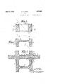
- FIGS. 3 and 4 are views on an enlarged scale showing certain details appearing in Fig; 1;
- Fig. 5 is a section on the line 55 of Fig. 3.
- a dam of the so-called hollow type having an inclined up-stream water-bearing deck 1 and beneath the deck a plurality of supports here shown as buttresses 2 extending down stream from the deck.
- the deck is shown as of the flat slab type, but any other suitable form of water-bearing surface may be employed as, for example, the arch or dome t e.
- joints 3 which may be either contraction or construction joints. Any side thrust which may occur at one support on one side of a joint is, according to my invent1on, distributed approximately equally to both sides of a joint in the adjacent support and this may be done by providing adjacent the joints 3 a brace, here shown as longitudinal members 4' hearing at opposite ends against the supports on opposite sides of the joints 3 and connected by cross-bracing members 5.
- brace As shown in Fig. 3, suitable reinforcing may be employed in these members to tie them together so that the entire brace will act as a unitary structural element whereby the'thrust originating, let us say, on the up-stream side of the joints 3 will'be transmitted to both upstream and down-stream sides of joints 3 and an adjacent support.
- Fig. 5 I have shown one 1 of the members 4 as integrally-connected to a support 2 on one side of the joints 3 and'the other member 4 as having a Joint with the In t s form the latter member 4 is provided suppgrt on the opposite side of the joints 3.
- a dam aninclined up-stream waterbearing deck, a plurality of supports disposed beneath said deck and extending down stream therefrom, each support having a joint therein, and braces between adjacent supports, comprising members engaging a support on both sides of said joint, and means tying said members together to form a unitary brace.
- an inclined up-stream waterbearing deck a plurality of supportsdisposed beneath said deck and extending down stream therefrom, each support having a. joint therein, and braces between adjacent supports, comprising members engaging a support on both sides of said joint, means tying said members together to form a unitary brace, and a joint between at least one of said members and the support constructed to permit movement of the support transversely of the member.
- an inclined up-stream water bearing deck a plurality of supports disposed beneath said deck and extending down stream therefrom, at least two adjacent supports having each a joint therein, and members arranged to transmit thrust from one side of a joint in one support to both sides of the joint in the other support.
- an inclined up-strea-m waterbearing deck a plurality of supports disposed beneath sai'd deck and extending down stream therefrom, at least two adjacent supports having each a joint therein, and members arranged to transmit thrust from one side of a joint in one support to both sides of the joint in the other support, said means permitting opening and closing of the joints in an upand down-stream direction.
Landscapes
- Engineering & Computer Science (AREA)
- Structural Engineering (AREA)
- General Engineering & Computer Science (AREA)
- Mechanical Engineering (AREA)
- Civil Engineering (AREA)
- Bridges Or Land Bridges (AREA)
Description
April 3 V c. v. DAVIS 5 DAM INV TOR C. V. DAVIS April 12, -1 932.
DAM
Filed May 5, 1950 2 Sheets-Sheet 2 Patented 'A i. 12,- 1932;
NITED STATES. PATENT OFFIC CALVIN v. DAVIS, .OF'EOUN'I vmmon, m Yonx, assmno'n 'ro' mum con- BTRUCTION: COMPANY, INC 013 NEW YORK, N. Y., A CORPORATION NEW YORK nan Application filed Kay 5, 1930. Serial No. 449,935.
This invention relates to a novel and improved form of dam, the novel features of which will be best understood from the following description and the annexed drawings, in which I have shown a selected-embod1- ment of the invention, and in which Fig. 1 is a vertical sectional view through a dam constructed according to this invention- Fig. 2 is a section on the line 22 of Fig. 1;
Figs. 3 and 4 are views on an enlarged scale showing certain details appearing in Fig; 1;
Fig. 5 is a section on the line 55 of Fig. 3.
Referring first to Fig. 1, I have shown therein a dam of the so-called hollow type having an inclined up-stream water-bearing deck 1 and beneath the deck a plurality of supports here shown as buttresses 2 extending down stream from the deck. The deck is shown as of the flat slab type, but any other suitable form of water-bearing surface may be employed as, for example, the arch or dome t e.
iin this type of dam the supports are often provided with joints 3 which may be either contraction or construction joints. Any side thrust which may occur at one support on one side of a joint is, according to my invent1on, distributed approximately equally to both sides of a joint in the adjacent support and this may be done by providing adjacent the joints 3 a brace, here shown as longitudinal members 4' hearing at opposite ends against the supports on opposite sides of the joints 3 and connected by cross-bracing members 5.
As shown in Fig. 3, suitable reinforcing may be employed in these members to tie them together so that the entire brace will act as a unitary structural element whereby the'thrust originating, let us say, on the up-stream side of the joints 3 will'be transmitted to both upstream and down-stream sides of joints 3 and an adjacent support.
- Referring now to Fig. 5, I have shown one 1 of the members 4 as integrally-connected to a support 2 on one side of the joints 3 and'the other member 4 as having a Joint with the In t s form the latter member 4 is provided suppgrt on the opposite side of the joints 3.
with a head 6 received a recess 7 in the support and the head is made slightly narrower than the width of the recess, as measured up and down stream, or transversely of the member 4, so that a certain amount of transverse play may take'place. I have indicated at 8 an amount of relative movement between the two parts of the support on opposite sides of the joints 3, this taking place during expansion and contraction in the support. In order to relieve the braces of stress due to this opening and closing of the joints 3, the above described construction is employed which will permit movement of the support 2-on one side of the joints 3 transversely of the member 4. Suitable material, such as asphalt, will be employed between the sides of the head 6 and the adjacent sides of the recess in which they are received.
While I have shown and described one member 4. as being integral with a support and the other side having a sliding joint therewith, nevertheless it is within the scope of my invention to make both members 4 with sliding joints between them and the supports.
An incidental advantage of the invention 7 other, and more efi'ectively and efficiently distriguting the stresses through the bracing it- I claim: 1. In a dam, aninclined up-stream waterbearing deck, a plurality of supports disposed beneath said deck and extending down stream therefrom, each support having a joint therein, and braces between adjacent supports, comprising members engaging a support on both sides of said joint, and means tying said members together to form a unitary brace.
,2. In a dam, an inclined up-stream waterbearing deck, a plurality of supportsdisposed beneath said deck and extending down stream therefrom, each support having a. joint therein, and braces between adjacent supports, comprising members engaging a support on both sides of said joint, means tying said members together to form a unitary brace, and a joint between at least one of said members and the support constructed to permit movement of the support transversely of the member.
3. In a dam, an inclined up-stream water bearing deck, a plurality of supports disposed beneath said deck and extending down stream therefrom, at least two adjacent supports having each a joint therein, and members arranged to transmit thrust from one side of a joint in one support to both sides of the joint in the other support.
4. In a dam, an inclined up-strea-m waterbearing deck, a plurality of supports disposed beneath sai'd deck and extending down stream therefrom, at least two adjacent supports having each a joint therein, and members arranged to transmit thrust from one side of a joint in one support to both sides of the joint in the other support, said means permitting opening and closing of the joints in an upand down-stream direction.-
CALVIN V. DAVIS.
Priority Applications (1)
| Application Number | Priority Date | Filing Date | Title |
|---|---|---|---|
| US449935A US1853668A (en) | 1930-05-05 | 1930-05-05 | Dam |
Applications Claiming Priority (1)
| Application Number | Priority Date | Filing Date | Title |
|---|---|---|---|
| US449935A US1853668A (en) | 1930-05-05 | 1930-05-05 | Dam |
Publications (1)
| Publication Number | Publication Date |
|---|---|
| US1853668A true US1853668A (en) | 1932-04-12 |
Family
ID=23786072
Family Applications (1)
| Application Number | Title | Priority Date | Filing Date |
|---|---|---|---|
| US449935A Expired - Lifetime US1853668A (en) | 1930-05-05 | 1930-05-05 | Dam |
Country Status (1)
| Country | Link |
|---|---|
| US (1) | US1853668A (en) |
-
1930
- 1930-05-05 US US449935A patent/US1853668A/en not_active Expired - Lifetime
Similar Documents
| Publication | Publication Date | Title |
|---|---|---|
| US364077A (en) | Windmill-tower | |
| CN212104209U (en) | Basement exterior wall construction joint structure adopting sectional type stirrups | |
| DE2638990A1 (en) | HEAT EXCHANGE PLATE FOR SHAFT WALL | |
| US1853668A (en) | Dam | |
| US1844484A (en) | Jetty | |
| US2736334A (en) | Twin-arch pipe line span | |
| US762632A (en) | Truss-bridge. | |
| US1864976A (en) | Dam | |
| US1840540A (en) | Dam | |
| JP3859328B2 (en) | Wooden sluice door and sluice gate using the same | |
| US764916A (en) | Concrete dam. | |
| US1681427A (en) | noetzli | |
| US2407952A (en) | Dam structure | |
| US1814509A (en) | Dam | |
| US1941183A (en) | Dam | |
| EP4049731B1 (en) | Sports track and track segment for a sports track | |
| US2133256A (en) | Method of building a dam | |
| US1906535A (en) | Dam | |
| US1846839A (en) | Dam | |
| US1097916A (en) | Dam. | |
| US207843A (en) | Improvement in docks | |
| US2029224A (en) | Dam | |
| US2430018A (en) | Demountable flume construction | |
| US1933092A (en) | Dam | |
| US1282087A (en) | Dam construction. |