US1853665A - Means for loading ball races or the like - Google Patents
Means for loading ball races or the like Download PDFInfo
- Publication number
- US1853665A US1853665A US466871A US46687130A US1853665A US 1853665 A US1853665 A US 1853665A US 466871 A US466871 A US 466871A US 46687130 A US46687130 A US 46687130A US 1853665 A US1853665 A US 1853665A
- Authority
- US
- United States
- Prior art keywords
- balls
- races
- condenser
- container
- ball
- Prior art date
- Legal status (The legal status is an assumption and is not a legal conclusion. Google has not performed a legal analysis and makes no representation as to the accuracy of the status listed.)
- Expired - Lifetime
Links
- 238000000034 method Methods 0.000 description 5
- 238000004519 manufacturing process Methods 0.000 description 3
- 241001446467 Mama Species 0.000 description 1
- 244000273618 Sphenoclea zeylanica Species 0.000 description 1
- 238000010276 construction Methods 0.000 description 1
- 230000008878 coupling Effects 0.000 description 1
- 238000010168 coupling process Methods 0.000 description 1
- 238000005859 coupling reaction Methods 0.000 description 1
- 235000000396 iron Nutrition 0.000 description 1
- 101150081985 scrib gene Proteins 0.000 description 1
Images
Classifications
-
- F—MECHANICAL ENGINEERING; LIGHTING; HEATING; WEAPONS; BLASTING
- F16—ENGINEERING ELEMENTS AND UNITS; GENERAL MEASURES FOR PRODUCING AND MAINTAINING EFFECTIVE FUNCTIONING OF MACHINES OR INSTALLATIONS; THERMAL INSULATION IN GENERAL
- F16C—SHAFTS; FLEXIBLE SHAFTS; ELEMENTS OR CRANKSHAFT MECHANISMS; ROTARY BODIES OTHER THAN GEARING ELEMENTS; BEARINGS
- F16C43/00—Assembling bearings
- F16C43/04—Assembling rolling-contact bearings
- F16C43/06—Placing rolling bodies in cages or bearings
-
- Y—GENERAL TAGGING OF NEW TECHNOLOGICAL DEVELOPMENTS; GENERAL TAGGING OF CROSS-SECTIONAL TECHNOLOGIES SPANNING OVER SEVERAL SECTIONS OF THE IPC; TECHNICAL SUBJECTS COVERED BY FORMER USPC CROSS-REFERENCE ART COLLECTIONS [XRACs] AND DIGESTS
- Y10—TECHNICAL SUBJECTS COVERED BY FORMER USPC
- Y10T—TECHNICAL SUBJECTS COVERED BY FORMER US CLASSIFICATION
- Y10T29/00—Metal working
- Y10T29/53—Means to assemble or disassemble
- Y10T29/53104—Roller or ball bearing
-
- Y—GENERAL TAGGING OF NEW TECHNOLOGICAL DEVELOPMENTS; GENERAL TAGGING OF CROSS-SECTIONAL TECHNOLOGIES SPANNING OVER SEVERAL SECTIONS OF THE IPC; TECHNICAL SUBJECTS COVERED BY FORMER USPC CROSS-REFERENCE ART COLLECTIONS [XRACs] AND DIGESTS
- Y10—TECHNICAL SUBJECTS COVERED BY FORMER USPC
- Y10T—TECHNICAL SUBJECTS COVERED BY FORMER US CLASSIFICATION
- Y10T29/00—Metal working
- Y10T29/53—Means to assemble or disassemble
- Y10T29/53478—Means to assemble or disassemble with magazine supply
Definitions
- This invention relates to means for filling the races of anti-friction or ball-bearings with the anti-friction or ball members.
- t is therefore the principal object of my an invention to provide a ra id method of filling these ball races, and while I have shown my invention in use with a special type of bearing, it is not necessarily so limited in its aplication, but the method may be used if ound advantageous, in the loading of ot er ball retainers or races for other types of bearings.
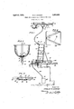
- Figure 1 is a somewhat schematic illustration of the method employed in filling the ball races of a five-gang condenser unit such as illustrated in my application previously referred to.
- Figure 2 is a part-sectional and part-elevational view on a reduced scale of a container carrying a large supply of balls to be used for filling the races.
- Figure 3 is a view of the selector for passin the balls to the races or retainers.
- igure 4 is a plan view of a pan used at the ball-race filling station.
- 1 is asupport carrying a member 2 to WlllCll is attached a bracket 3.
- Carried on the bracket 3 is a small electric motor 4 having a pulley 5 which is connected in any suitable manner by means of a circular belt 6 to a pulley 7 carried on a shaft 8.
- the shaft 8 extends downward to a point near the bottom of a container 9 which is fastoned to the member 2.
- the lower part of to the stem 11 by any suitable fitting 17.
- the container 9 has an openin 10 leading therefrom, this opening 10 pre erably being positioned" in a hollow stem 11 fastened to the container 9 in any satisfactory manner.
- the lower end of the shaft 8 is hollow, as indicated by 12, and is also provided with at least one spiral groove 13 which extends through the wall of the shaft into the hollow portion 12.
- a member 14 which I term an agitator and which acts, when the shaft 8 is turned by the motor 4, to move or agitate the balls 15 within the container 9 so that they will be continuously fed into the spiral groove 13 and into the hollow portion 12 of the shaft 8.
- the hollow part 1.2 of the shaft 8 is in alignment with the opening 10, so that the balls pass into the spiral groove and from there into a flexible tube 16 which is fastened On the free end of the flexible tube 16, is
- the selector includes a tube 19. having a nozzle end 20 and a. control lever 21.
- the lever 21 is pivoted at 22 to a bracket 23 carried on the tube 19.
- a member 41 Carried by thelever 21 is a member 41 having a pair of fingers 24 and 25.
- a spring 26 acts to hold thelever 21 in the position shown in Figure 3, whereby the finger 24 obstructs the passageway 27 in the tube 19 so that the balls coming. through the flexible tube 16 will notrun out of the nozzle 20 prom-iscuously.
- fingers 24 and 25 may be made an integral part of the lever 21.
- a pan 28 is provided on a bench'29 and to the bench is attached a system of levers operated by a foot pedal 30.
- One end, or 31, or thelevers extends through the bench 29 into the pan 28 and is adapted to be engaged by the end 32 of the operating shaft of the condenser, a five-unit gang being illustrated generally'by the number 33.
- gang condensers are mounted on a common framework and the frame of the condenser is adapted to rest against" a bracket 34 held in position by a brace 35', the bottom part of the frame being supported on a shelf 36, and the outer edge of the lower portion of the frame rests on an adjustable screw 37 which may be adjusted so as to brin the condenser into the position shown in %igure 1, whereby it is fully supported at the bottom and back, as well as having side'supports by means of a U-shaped bracket 38 carried by the bracket 34.
- the system of levers previously referred to are normally held in what may be termed a non-loading position by a spring 39.
- the fingers 24 and 25 are spaced longitudinally from each other so as to provide the exact number of balls to fill the race, and that the selector may be made to suit the type of race and size of balls required.
- the operator releases .the pressure on the foot pedal 30 and the shaft drops back in place and the top race, which is usually constructed so that it may be filled without raising the shaft, may be then filled and the condenser removed and passed to another operator for applying the ball-retaining plate to the framework of the condenser.
- the pan 28 is preferably placed at a slight angle on the bench and may be'provided with u1de members 41 in the form of small angle.
- a hole 42 is located at the apex of the members 41 and a passagewa 44 is provided between a receptacle 45 an the pipe 43 leading to opening 42.
- the passageway 44 may be in the form of a pipe connected by couplings 18, the same as p'reviouslyreferred to.
- the pan 28, pipe 44, and receptacle 45 are used to catch and collect any balls which may be spilled by the operator during the filling operation.
- Apparatus for filling the ball races of the rotor bearings of an electrical condenser including a manually operable lever at a race filling station, means for supporting the condenser frame so one end of the rotor shaft is closely opposite one'end of said lever whereby when the lever is operated, the rotor shaft may be moved longitudinally to expose at least one of said races, a container carrying a quantity of balls, a tube leading from the container to the condenser race filling station, means within the container to feed the balls therein to said tube, means for operating said just previously mentioned means, and a selector positioned at the free end of said tube to select a definite number of balls and to then pass them at the will of. the operator into the condenser rotor bearing race.
- Apparatus for loading ball races including;.a race filling station consisting of a pan having supports to receive members carrying said races mounted within the confines of the pan, a container for carrying a quantity of balls, a tube leading from the container .for conveying balls therefrom to' said station, means within the container for insuring a steady flow of balls through the tulbge, a ball selector on the station end of'the tu e.
- Apparatus for filling the ball races of the rotor bearings of an electrical condenser including; a race filling station consisting of a pan set at an angle and having supports within the confines of the pan for receiving I the condenser frame, amember p.
Landscapes
- Engineering & Computer Science (AREA)
- General Engineering & Computer Science (AREA)
- Mechanical Engineering (AREA)
- Basic Packing Technique (AREA)
Description
April 12,- 1932. s. s. CRAMER Y MEANS LOADING BALL RACE IS OR THE LIKE Filed; July 9, 19:50
Patented Apr. 12, 1932 UNITED STATES PATENT OFFICE STANLEY 8. OF HADDON HEIGHTS, NEW JERSEY, ASSIGNOR TO RADIO COIN DENSER COMPANY, OF CAMDEN, NEW JERSEY mama non Lemme BALL RACES or. ran mxn Application filed July 9,
This invention relates to means for filling the races of anti-friction or ball-bearings with the anti-friction or ball members.
In my application, Serial No. 332,700, filed January 15, 1929 I have shown and described a plural unit ball-bearing electrical condenser particularly useful in radio receiving sets. v
The production of such condensers runs into large numbers and in order to reduce the cost of construction and speed up the rate of production; or stated in another way, to get mass production at the lowest cost, I have found it necessary to find some means of elim- 5 inating the labor of picking up the individual balls and placing them in the respective races, two of these races being shown in the ap lication above referred to.
t is therefore the principal object of my an invention to provide a ra id method of filling these ball races, and while I have shown my invention in use with a special type of bearing, it is not necessarily so limited in its aplication, but the method may be used if ound advantageous, in the loading of ot er ball retainers or races for other types of bearings.-
. In the drawings:
Figure 1 is a somewhat schematic illustration of the method employed in filling the ball races of a five-gang condenser unit such as illustrated in my application previously referred to.
Figure 2 is a part-sectional and part-elevational view on a reduced scale of a container carrying a large supply of balls to be used for filling the races.
Figure 3 is a view of the selector for passin the balls to the races or retainers.
igure 4 is a plan view of a pan used at the ball-race filling station.
In the drawmgs, 1 is asupport carrying a member 2 to WlllCll is attached a bracket 3. Carried on the bracket 3 is a small electric motor 4 having a pulley 5 which is connected in any suitable manner by means of a circular belt 6 to a pulley 7 carried on a shaft 8. The shaft 8 extends downward to a point near the bottom of a container 9 which is fastoned to the member 2. The lower part of to the stem 11 by any suitable fitting 17.
1930. Serial No. 466,871.
the container 9 has an openin 10 leading therefrom, this opening 10 pre erably being positioned" in a hollow stem 11 fastened to the container 9 in any satisfactory manner. The lower end of the shaft 8 is hollow, as indicated by 12, and is also provided with at least one spiral groove 13 which extends through the wall of the shaft into the hollow portion 12. On the inner end of the shaft 8, is carried a member 14 which I term an agitator and which acts, when the shaft 8 is turned by the motor 4, to move or agitate the balls 15 within the container 9 so that they will be continuously fed into the spiral groove 13 and into the hollow portion 12 of the shaft 8. The hollow part 1.2 of the shaft 8 is in alignment with the opening 10, so that the balls pass into the spiral groove and from there into a flexible tube 16 which is fastened On the free end of the flexible tube 16, is
attached a selector by means of a suitable fitting 18 somewhat similar to 17. The selector includes a tube 19. having a nozzle end 20 and a. control lever 21. The lever 21 is pivoted at 22 to a bracket 23 carried on the tube 19.
Carried by thelever 21 is a member 41 having a pair of fingers 24 and 25. A spring 26 acts to hold thelever 21 in the position shown in Figure 3, whereby the finger 24 obstructs the passageway 27 in the tube 19 so that the balls coming. through the flexible tube 16 will notrun out of the nozzle 20 prom-iscuously. The
As shown in Figures 1 and 4, a pan 28 is provided on a bench'29 and to the bench is attached a system of levers operated by a foot pedal 30. One end, or 31, or thelevers extends through the bench 29 into the pan 28 and is adapted to be engaged by the end 32 of the operating shaft of the condenser, a five-unit gang being illustrated generally'by the number 33. These gang condensers are mounted on a common framework and the frame of the condenser is adapted to rest against" a bracket 34 held in position by a brace 35', the bottom part of the frame being supported on a shelf 36, and the outer edge of the lower portion of the frame rests on an adjustable screw 37 which may be adjusted so as to brin the condenser into the position shown in %igure 1, whereby it is fully supported at the bottom and back, as well as having side'supports by means of a U-shaped bracket 38 carried by the bracket 34. The system of levers previously referred to are normally held in what may be termed a non-loading position by a spring 39.
Coming now to the operation of my apparatus and and assuming that the motor 4 is running and that the container 9 is full of balls, the flexible tube 16 and selector will also be full down to the finger 24. Pressure on the foot pedal 30 by the operator allows the end.
of the lever 31 to raise the condenser shaft sufiiciently so thatthe race therein is exposed to receive the balls. The operator then presses on the free end of the lever 21, causing the finger 25 to trap the balls between the fingers 24 and 25 and to stop any more from coming out of the flexible tube 16. The finger 24 is removed from the passageway 27 and the selected number of balls between the fingers 24 and 25 are allowed to pass into the ball race 40, it bein understood that this is the one to be filled rst.
It is also to be understood that the fingers 24 and 25 are spaced longitudinally from each other so as to provide the exact number of balls to fill the race, and that the selector may be made to suit the type of race and size of balls required.
Immediately that the race is filled, the operator releases .the pressure on the foot pedal 30 and the shaft drops back in place and the top race, which is usually constructed so that it may be filled without raising the shaft, may be then filled and the condenser removed and passed to another operator for applying the ball-retaining plate to the framework of the condenser.
The pan 28 is preferably placed at a slight angle on the bench and may be'provided with u1de members 41 in the form of small angle.
irons placed somewhat as shown in Figure 4. A hole 42 is located at the apex of the members 41 and a passagewa 44 is provided between a receptacle 45 an the pipe 43 leading to opening 42. The passageway 44 may be in the form of a pipe connected by couplings 18, the same as p'reviouslyreferred to. The pan 28, pipe 44, and receptacle 45 are used to catch and collect any balls which may be spilled by the operator during the filling operation.
By theapparatus and method herein described, I have provideda very expeditious manner of filling-ball races, and while I have shown a method which is a practical operation for filling ball races of condensers, I do not wish to-be unduly limited by the specification or the scope of the appended claims.
Having thus d scrib d my inv ntion, what I claim is:
1. Apparatus for filling the ball races of the rotor bearings of an electrical condenser including a manually operable lever at a race filling station, means for supporting the condenser frame so one end of the rotor shaft is closely opposite one'end of said lever whereby when the lever is operated, the rotor shaft may be moved longitudinally to expose at least one of said races, a container carrying a quantity of balls, a tube leading from the container to the condenser race filling station, means within the container to feed the balls therein to said tube, means for operating said just previously mentioned means, and a selector positioned at the free end of said tube to select a definite number of balls and to then pass them at the will of. the operator into the condenser rotor bearing race.
2. Apparatus for filling the ball races of from the container for conveying balls therefrom to said station, and a selector at the free end of the tube at the station to select a definite number of balls and to then pass them, at the will-of the operator, to the rotor bearing race desired to-be filled.
3. Apparatus for loading ball races including;.a race filling station consisting of a pan having supports to receive members carrying said races mounted within the confines of the pan, a container for carrying a quantity of balls, a tube leading from the container .for conveying balls therefrom to' said station, means within the container for insuring a steady flow of balls through the tulbge, a ball selector on the station end of'the tu e.
4. Apparatus for filling the ball races of the rotor bearings of an electrical condenser including; a race filling station consisting of a pan set at an angle and having supports within the confines of the pan for receiving I the condenser frame, amember p.
through the bottom of the pan at a point to engage the end of the condenser'rotor shaft when the condenser frame is in position on 7 said supports, manually operable means for actuating said member to move the rotor shaft longitudinally of the condenser frame to expose at least one of saidraces, a container for carrying a quantity of balls, a tube leading from the container for conveying balls therefrom to said station, means within the container for insurin a steady. flow of balls through the tube, a. all selector at the station end of the tube, said pan having an outlet at its lowest floint, whereby balls that may accidentally fa into the pan during the filling o oration, will ass to said outlet, and means or catching t e balls coming from said outlet.
In testimony whereof, I aflix STANLE m s'gnature. Y S. CllAMER.
Priority Applications (1)
| Application Number | Priority Date | Filing Date | Title |
|---|---|---|---|
| US466871A US1853665A (en) | 1930-07-09 | 1930-07-09 | Means for loading ball races or the like |
Applications Claiming Priority (1)
| Application Number | Priority Date | Filing Date | Title |
|---|---|---|---|
| US466871A US1853665A (en) | 1930-07-09 | 1930-07-09 | Means for loading ball races or the like |
Publications (1)
| Publication Number | Publication Date |
|---|---|
| US1853665A true US1853665A (en) | 1932-04-12 |
Family
ID=23853417
Family Applications (1)
| Application Number | Title | Priority Date | Filing Date |
|---|---|---|---|
| US466871A Expired - Lifetime US1853665A (en) | 1930-07-09 | 1930-07-09 | Means for loading ball races or the like |
Country Status (1)
| Country | Link |
|---|---|
| US (1) | US1853665A (en) |
Cited By (3)
| Publication number | Priority date | Publication date | Assignee | Title |
|---|---|---|---|---|
| US2897582A (en) * | 1955-11-08 | 1959-08-04 | Lempco Products Inc | Method of producing a ball-bearing assembly |
| EP0887146A3 (en) * | 1997-06-26 | 1999-10-06 | Samsung Electronics Co., Ltd. | Apparatus for dispensing balls |
| US11131345B2 (en) * | 2018-07-19 | 2021-09-28 | Ningbo Baoheng Bearing Fittings Manufacturing Co. Ltd. | Bearing steel ball assembly device |
-
1930
- 1930-07-09 US US466871A patent/US1853665A/en not_active Expired - Lifetime
Cited By (3)
| Publication number | Priority date | Publication date | Assignee | Title |
|---|---|---|---|---|
| US2897582A (en) * | 1955-11-08 | 1959-08-04 | Lempco Products Inc | Method of producing a ball-bearing assembly |
| EP0887146A3 (en) * | 1997-06-26 | 1999-10-06 | Samsung Electronics Co., Ltd. | Apparatus for dispensing balls |
| US11131345B2 (en) * | 2018-07-19 | 2021-09-28 | Ningbo Baoheng Bearing Fittings Manufacturing Co. Ltd. | Bearing steel ball assembly device |
Similar Documents
| Publication | Publication Date | Title |
|---|---|---|
| CN105422650B (en) | Automatic ball loading machine for plane bearing retainer | |
| CN106882406B (en) | Automatic USB flash disk arranging machine | |
| US1853665A (en) | Means for loading ball races or the like | |
| US1609994A (en) | Automatic feed mechanism | |
| US1723369A (en) | Apparatus for assembling bearings | |
| CN117178778A (en) | A kind of self-through hole double suction cup horizontal disc seedling raising production line | |
| CN108489749B (en) | A test bench for potato metering device with recyclable soil | |
| CN104145573B (en) | A kind of vacuum planters | |
| US2372755A (en) | Impregnating apparatus | |
| US1437431A (en) | A copvpobation of illi | |
| US2507883A (en) | Pharmaceutical machine for delivering to receptacles predetermined quantities of pharmaceutical articles such as pills, tablets, and the like | |
| US866702A (en) | Machine for coating confectionery. | |
| US1997078A (en) | Vending machine | |
| USRE21425E (en) | Dough twisting machine | |
| US935504A (en) | Can-filling machine. | |
| US3124173A (en) | tiffany | |
| US2031417A (en) | Roller bearing assembling machine | |
| US1381419A (en) | Sack-lining machine | |
| CN108093966A (en) | Automatically continuously spread native device | |
| US2732052A (en) | Control apparatus for grain distributing spouts | |
| US1984712A (en) | Spool stand | |
| US2608307A (en) | Device for visual inspection of metallic balls | |
| CN101766902B (en) | Ball-sending device | |
| CN116553241B (en) | Unreeling bracket mechanism of cloth inspecting machine | |
| CN222364763U (en) | A thrust bearing axial seismic resistance testing device |