US1853664A - Rotor shaft for electrical condensers - Google Patents
Rotor shaft for electrical condensers Download PDFInfo
- Publication number
- US1853664A US1853664A US354468A US35446829A US1853664A US 1853664 A US1853664 A US 1853664A US 354468 A US354468 A US 354468A US 35446829 A US35446829 A US 35446829A US 1853664 A US1853664 A US 1853664A
- Authority
- US
- United States
- Prior art keywords
- rotor
- shaft
- sections
- rotor shaft
- plates
- Prior art date
- Legal status (The legal status is an assumption and is not a legal conclusion. Google has not performed a legal analysis and makes no representation as to the accuracy of the status listed.)
- Expired - Lifetime
Links
- 238000009413 insulation Methods 0.000 description 8
- 239000012212 insulator Substances 0.000 description 3
- 239000000463 material Substances 0.000 description 1
- 239000002184 metal Substances 0.000 description 1
Images
Classifications
-
- H—ELECTRICITY
- H01—ELECTRIC ELEMENTS
- H01G—CAPACITORS; CAPACITORS, RECTIFIERS, DETECTORS, SWITCHING DEVICES, LIGHT-SENSITIVE OR TEMPERATURE-SENSITIVE DEVICES OF THE ELECTROLYTIC TYPE
- H01G5/00—Capacitors in which the capacitance is varied by mechanical means, e.g. by turning a shaft; Processes of their manufacture
- H01G5/04—Capacitors in which the capacitance is varied by mechanical means, e.g. by turning a shaft; Processes of their manufacture using variation of effective area of electrode
- H01G5/06—Capacitors in which the capacitance is varied by mechanical means, e.g. by turning a shaft; Processes of their manufacture using variation of effective area of electrode due to rotation of flat or substantially flat electrodes
-
- Y—GENERAL TAGGING OF NEW TECHNOLOGICAL DEVELOPMENTS; GENERAL TAGGING OF CROSS-SECTIONAL TECHNOLOGIES SPANNING OVER SEVERAL SECTIONS OF THE IPC; TECHNICAL SUBJECTS COVERED BY FORMER USPC CROSS-REFERENCE ART COLLECTIONS [XRACs] AND DIGESTS
- Y10—TECHNICAL SUBJECTS COVERED BY FORMER USPC
- Y10T—TECHNICAL SUBJECTS COVERED BY FORMER US CLASSIFICATION
- Y10T403/00—Joints and connections
- Y10T403/33—Transverse rod to spaced plate surfaces
-
- Y—GENERAL TAGGING OF NEW TECHNOLOGICAL DEVELOPMENTS; GENERAL TAGGING OF CROSS-SECTIONAL TECHNOLOGIES SPANNING OVER SEVERAL SECTIONS OF THE IPC; TECHNICAL SUBJECTS COVERED BY FORMER USPC CROSS-REFERENCE ART COLLECTIONS [XRACs] AND DIGESTS
- Y10—TECHNICAL SUBJECTS COVERED BY FORMER USPC
- Y10T—TECHNICAL SUBJECTS COVERED BY FORMER US CLASSIFICATION
- Y10T403/00—Joints and connections
- Y10T403/70—Interfitted members
- Y10T403/7018—Interfitted members including separably interposed key
- Y10T403/7021—Axially extending
-
- Y—GENERAL TAGGING OF NEW TECHNOLOGICAL DEVELOPMENTS; GENERAL TAGGING OF CROSS-SECTIONAL TECHNOLOGIES SPANNING OVER SEVERAL SECTIONS OF THE IPC; TECHNICAL SUBJECTS COVERED BY FORMER USPC CROSS-REFERENCE ART COLLECTIONS [XRACs] AND DIGESTS
- Y10—TECHNICAL SUBJECTS COVERED BY FORMER USPC
- Y10T—TECHNICAL SUBJECTS COVERED BY FORMER US CLASSIFICATION
- Y10T403/00—Joints and connections
- Y10T403/70—Interfitted members
- Y10T403/7047—Radially interposed shim or bushing
Definitions
- the rotor groups on the shaft 1 and their associated stators may be, and in the cases mentioned are,- substantially different in capacity one from the other so as to meet the circuitl requirements.
- any one or all of the sections, A, B, C, and D may be arranged with insulation the same as proposed for sections A and C, according to the circuit requirements.
- Our design of shaft makes it easily possible to make a gang condenser llaving all the stators and rotors insulated each from the other, or any one or all of the stators may be mounted directly on metal, thereby grounding them to the frame which is usually connected to thecircuit ground, in which case the corresponding rotor would be insulated as has beenpointed out.
- a rotor shaft for an electrical condenser comprising; a metallic rod having spaced sections adapted to receive sleeves carrying groups of rotor plates, at least one of said sections being reduced ⁇ in diameter and having a slot cut therein and insulation then moulded over said reduced diameter portion and into the slot to the full diameter of the shaft, whereby a rotor sleevewith its plates may be slipped thereon and anchored to the insulation.
- a rotor shaft for an electrical condenser comprising; a metallic rod having spaced sections adapted to receive sleeves carrying groups of rotor plates, at least one of said sections being reduced in' diameter and having anchor means constructed thereon and insulation vmoulded oversaid reducedl portion and anchor means, to substantially the full diameter of the shaft whereby arotor sleeve with its plates ma be slipped thereon and anchored to the insulation.
- a rotor shaft for an electrical condenser comprising; a metallic rod having spaced sections adapted to receive sleeves carrying groups of rotor plates, a plurality of said sections being reduced in diameter and each having anchor means constructed thereon and insulation moulded over said reduced portions and anchor means to substantially the full diameter of the shaft wherebyy rotor sleeves with their plates may be slipped over the insulated sections and fastened to the insulation.
- a rotor shaft for an electrical condenser comprising; a metallic rod having spacedv ⁇ sections adapted to receive sleeves carrying groups of rotor plates, a plurality of keyways cut in said shaft sections, insulating strips set in said keyways, said strips extending outwardly from the shaft to receive arotor sleeve thereon, and means carried by the sleeve to fasten it to at least one of said strips.
- a rotor shaft for an electrical condenser comprising; a metallic rod having spaced sections adapted to receive sleeves carrying groups of rotor plates, means for mounting said rotor groups on said shaft sections and at the same time reduce the surface leakage, consisting of a plurality of spaced insulators carried vby said shaft so as to support said rotor sleeves.
- a rotor shaft for an electrical condenser comprising; a metallic rod having spaced sections adapted to receive sleeves carrying groups of rotor plates, means for mounting said rotor groups on said shaft sections and at the same time reduce the surface leakage, consisting of a plurality of arcuately spaced insulators carried by the shaft and having a length substantially the same as the rotor isleeve, but relatively narrow, whereby the areaof sleeve contact therewith is small.
- An electrical condenser including; a metallic shaft having sections adapted to receive sleeves carrying groups of rotor plates for forming with their stators, condensers of selected capacity, said shaft having special anchor means lixedly positioned at selected sections, and insulating means for the rotor sleeves at said sections, said insulating means cooperating with said anchor means to hold said insulating means from turning on the shaft, and clamping screw means for securely fastening the said rotor sleeves to the sulating means.
Landscapes
- Engineering & Computer Science (AREA)
- Power Engineering (AREA)
- Microelectronics & Electronic Packaging (AREA)
- Insulation, Fastening Of Motor, Generator Windings (AREA)
Description
'April 12, 1932- s. s. CRAMER ET AL 1,853,664
ROTOR SHAFT FORELFICTRICAL CONDENSERS Filed April 12, lsz
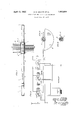
A TTU/NVE Y pensation or curve correction means. Therefore, the rotor groups on the shaft 1 and their associated stators may be, and in the cases mentioned are,- substantially different in capacity one from the other so as to meet the circuitl requirements.
It is tobe understood that any one or all of the sections, A, B, C, and D, may be arranged with insulation the same as proposed for sections A and C, according to the circuit requirements. Our design of shaft makes it easily possible to make a gang condenser llaving all the stators and rotors insulated each from the other, or any one or all of the stators may be mounted directly on metal, thereby grounding them to the frame which is usually connected to thecircuit ground, in which case the corresponding rotor would be insulated as has beenpointed out.
Our invention is susceptible of certain variationsas is shown in Figure 4, wherein the sleeve 5 is supported by three strips of insulation 9 forced into cooperating keyways similar to keyway 7, which preferably are equal to the length of the rotor sleeve. In
' this case, 4the set screws 6A engage one of the insulators 9 which are of substantial material to take and sustain the pressure of the screw.y Bymounting the rotor sleeves in this way, the capacity action between the sleeve andthe shaft. due to the dielectric therebetween is materially reduced. Other details lnay be varied without departing from the spirit of our invention or the scope of the appended claims. n
Having thus described our invention, what we claim is:
1. A rotor shaft for an electrical condenser comprising; a metallic rod having spaced sections adapted to receive sleeves carrying groups of rotor plates, at least one of said sections being reduced `in diameter and having a slot cut therein and insulation then moulded over said reduced diameter portion and into the slot to the full diameter of the shaft, whereby a rotor sleevewith its plates may be slipped thereon and anchored to the insulation.
2.; A rotor shaft for an electrical condenser comprising; a metallic rod having spaced sections adapted to receive sleeves carrying groups of rotor plates, at least one of said sections being reduced in' diameter and having anchor means constructed thereon and insulation vmoulded oversaid reducedl portion and anchor means, to substantially the full diameter of the shaft whereby arotor sleeve with its plates ma be slipped thereon and anchored to the insulation.
A rotor shaft for an electrical condenser comprising; a metallic rod having spaced sections adapted to receive sleeves carrying groups of rotor plates, a plurality of said sections being reduced in diameter and each having anchor means constructed thereon and insulation moulded over said reduced portions and anchor means to substantially the full diameter of the shaft wherebyy rotor sleeves with their plates may be slipped over the insulated sections and fastened to the insulation. i
4. A rotor shaft for an electrical condenser comprising; a metallic rod having spacedv` sections adapted to receive sleeves carrying groups of rotor plates, a plurality of keyways cut in said shaft sections, insulating strips set in said keyways, said strips extending outwardly from the shaft to receive arotor sleeve thereon, and means carried by the sleeve to fasten it to at least one of said strips.
6. A rotor shaft for an electrical condenser comprising; a metallic rod having spaced sections adapted to receive sleeves carrying groups of rotor plates, means for mounting said rotor groups on said shaft sections and at the same time reduce the surface leakage, consisting of a plurality of spaced insulators carried vby said shaft so as to support said rotor sleeves.
7. A rotor shaft for an electrical condenser comprising; a metallic rod having spaced sections adapted to receive sleeves carrying groups of rotor plates, means for mounting said rotor groups on said shaft sections and at the same time reduce the surface leakage, consisting of a plurality of arcuately spaced insulators carried by the shaft and having a length substantially the same as the rotor isleeve, but relatively narrow, whereby the areaof sleeve contact therewith is small.
8. An electrical condenser including; a metallic shaft having sections adapted to receive sleeves carrying groups of rotor plates for forming with their stators, condensers of selected capacity, said shaft having special anchor means lixedly positioned at selected sections, and insulating means for the rotor sleeves at said sections, said insulating means cooperating with said anchor means to hold said insulating means from turning on the shaft, and clamping screw means for securely fastening the said rotor sleeves to the sulating means.
In testimony whereof, we aix our signatures.
STANLEY S. CRAMER.
E. D. KOEPPING.
Priority Applications (1)
| Application Number | Priority Date | Filing Date | Title |
|---|---|---|---|
| US354468A US1853664A (en) | 1929-04-12 | 1929-04-12 | Rotor shaft for electrical condensers |
Applications Claiming Priority (1)
| Application Number | Priority Date | Filing Date | Title |
|---|---|---|---|
| US354468A US1853664A (en) | 1929-04-12 | 1929-04-12 | Rotor shaft for electrical condensers |
Publications (1)
| Publication Number | Publication Date |
|---|---|
| US1853664A true US1853664A (en) | 1932-04-12 |
Family
ID=23393450
Family Applications (1)
| Application Number | Title | Priority Date | Filing Date |
|---|---|---|---|
| US354468A Expired - Lifetime US1853664A (en) | 1929-04-12 | 1929-04-12 | Rotor shaft for electrical condensers |
Country Status (1)
| Country | Link |
|---|---|
| US (1) | US1853664A (en) |
Cited By (2)
| Publication number | Priority date | Publication date | Assignee | Title |
|---|---|---|---|---|
| DE759594C (en) * | 1939-06-23 | 1953-05-04 | Siemens & Halske A G | Multiple variable capacitor |
| US4444234A (en) * | 1981-11-19 | 1984-04-24 | Arasmith Stanley D | Log processing apparatus and method |
-
1929
- 1929-04-12 US US354468A patent/US1853664A/en not_active Expired - Lifetime
Cited By (2)
| Publication number | Priority date | Publication date | Assignee | Title |
|---|---|---|---|---|
| DE759594C (en) * | 1939-06-23 | 1953-05-04 | Siemens & Halske A G | Multiple variable capacitor |
| US4444234A (en) * | 1981-11-19 | 1984-04-24 | Arasmith Stanley D | Log processing apparatus and method |
Similar Documents
| Publication | Publication Date | Title |
|---|---|---|
| US1853664A (en) | Rotor shaft for electrical condensers | |
| US2439255A (en) | Capacitor switch | |
| US2006931A (en) | Electrical insulator | |
| ES429840A1 (en) | Multiple trimmer capacitor, particularly for adjustment of crystal oscillators | |
| US1973342A (en) | Electrical condenser | |
| US1743870A (en) | Electrical condenser | |
| US1848872A (en) | Electrical condenser | |
| US1959197A (en) | Variable condenser | |
| US1742468A (en) | Electrical condenser | |
| US1885596A (en) | Electrical apparatus | |
| US1626391A (en) | Variable air condenser | |
| US1613032A (en) | Variable condenser | |
| US1763771A (en) | Variable-capacity element | |
| US1700259A (en) | Variable condenser | |
| US1842374A (en) | Power factor condenser | |
| US1983121A (en) | Electrical condenser | |
| GB469915A (en) | Improvements in variable electric condensers | |
| US1827939A (en) | Electrical condenser | |
| US2015732A (en) | Condenser with temperature compensation | |
| US1949137A (en) | Variable condenser | |
| US1769130A (en) | Electrical condenser | |
| US1548015A (en) | Condenser-plate system | |
| GB303758A (en) | Improvements in variable electric condensers | |
| US1572504A (en) | Electrostatic condenser | |
| US1705734A (en) | Variable air condenser |