US1853661A - Television system - Google Patents
Television system Download PDFInfo
- Publication number
- US1853661A US1853661A US334413A US33441329A US1853661A US 1853661 A US1853661 A US 1853661A US 334413 A US334413 A US 334413A US 33441329 A US33441329 A US 33441329A US 1853661 A US1853661 A US 1853661A
- Authority
- US
- United States
- Prior art keywords
- disc
- film
- amplifier
- scanning
- receiving
- Prior art date
- Legal status (The legal status is an assumption and is not a legal conclusion. Google has not performed a legal analysis and makes no representation as to the accuracy of the status listed.)
- Expired - Lifetime
Links
Images
Classifications
-
- H—ELECTRICITY
- H04—ELECTRIC COMMUNICATION TECHNIQUE
- H04N—PICTORIAL COMMUNICATION, e.g. TELEVISION
- H04N5/00—Details of television systems
- H04N5/04—Synchronising
- H04N5/06—Generation of synchronising signals
- H04N5/067—Arrangements or circuits at the transmitter end
- H04N5/073—Arrangements or circuits at the transmitter end for mutually locking plural sources of synchronising signals, e.g. studios or relay stations
Definitions
- LATENT OFFICE ELECTRIC 8 MANUFACTURING COIvEPANY, CORPORATION OF PENNSYLVANIA TELEVISION SYSTEM Application filed January 23, 1929. Serial No. 334,413.
- My invention relates broadly to television systems and it has particular relation to the electrical reproduction, at a, distance, of printed or written messages, moving pictures, combined sound and picture films, and thelike.
- an object of my invention to provide a system whereby a.moving picturefilm may be electrically transmitted to a plurality of receiving stations, wherea-t a reproduction thereof may be projected upon a screen or a duplicate film may be made.
- Another object of my invention is to provide, in a system of the type described, means for maintaining motional synchronism between a view-transmitting device and a plurality of view-receiving devices.
- I provide means for moving acontinuous film at a con stant rate of speed between a fixed light source and a photoelectric cell.
- the cell is preferably of the high-vacuum, alkaline-hydride type, easily capable of responding to light-variation frequencies as high as 100,- 000 per second.
- the longitudinal component of the scanning operation is furnished by the movement of the film.
- the transverse component is introduced by interposing a device between the moving film and the photoelectric cell or be tween the film and the light source that causes frequency, and'th'e same high frequency is transmitted .by radio, or by wire, to the receiving stations'whereat it is: also utilized, after amplification, for applying motive power to the receiving. discs.
- the single figure of the drawing is a diagrammatic view, partly in perspective, of the apparatus and circuit connections constituting the sending portion of a television system comprising a preferred embodimentof my invention. 7 a
- the apparatus illustrated in the drawing comprises a storage reel 1, a take-up reel 2, a guiding device 3 for supporting a film 4:, and a'motor 5 for applying power to the take-up reel.
- the film is also given'motion longitudinally thereof by a rotating sprocket wheel 6, the teeth of which engage the marginal perforations in the film.
- the sprocket wheel 6 is mounted on a shaft 7 to which is affiXed-a spiral gear 8 that meshes with a spiral gear 9 mounted upon a countershaft 10 rotatably supported in suitable bearings 11.
- a gear wheel 12 is also affixed to the countershaft.
- the gear wheel 12 meshes with a relatively long gear wheel 13 that is afiixed to the end of a main shaft 14 which extends parallel to the countershaft and is rotatably supported between aplurality of bearings 15.
- Motive power is applied to the main shaft by a suitable constant-speed motor 16, preferably through a belt 17.
- the guide 3, through which the film travels, is provided with a plurality of oppositely disposed transverse openings 20 and 21.
- Light from a source 22 is focused on the opening 20 to brightly illuminate a narrow longitudinal element of the film, as it travels past the openings.
- An image of the illuminated portion of the film is formed, by a lens 23 upon the face of a disc 25 that is mounted upon the main shaft 14 between the bearing 15 and the elongated gear wheel 13.
- the disc is provided with a plurality of small square or sector-shape openings 26 disposed in a circular path adjacent to the perimeter thereof, the disc being so positioned that each of the openings is caused to successively traverse the film-element image where it, falls upon the face of the disc.
- the individual openings 26 are preferably formed in small discs 29 that overlie larger openings (not visible) in the disc itself, and are afiixed to the disc in any convenient way.
- the spacing between the openings is made slightly greater than the length of the filmelement image in order that the said image may be traversed by only one opening at a time.
- the countershaft 10 is slidably supported in the bearings 11 and an adjusting device 30 is provided whereby the shaft may be moved slightly in an axial direction.
- Such axial movement of the c'ountershaft inasmuch as the said shaft is prevented from rotating by the engagement of the gears 12 and 13, causes the spiral gear 8 to rotate slightly in the one or the other direction, depending upon the direction in which the shaft is moved.
- the rotation of the spiral gear causes the filmengaging sprocket 6 to move the film slightly forward or back without interrupting the constant advance thereof.
- a photo-electric cell 31 preferably of the alkaline-hydride type, is mounted rearwardly of the scanning disc 25 and is connected to the input terminals of an amplifier 32, prefera-bly of'the type comprising a plurality of thermionic'tubes and being capable of amplifying a wide range of frequencies.
- an amplifier 32 prefera-bly of'the type comprising a plurality of thermionic'tubes and being capable of amplifying a wide range of frequencies.
- the purpose for which the amplifier is utilized will be hereinafter explained more fully in detail.
- the periphery thereof is so provided with a plurality of teeth 33 that the disc constitutes the rotor element of a synchronous motor.
- the stator element of the motor comprises a continuous winding of the type fully disclosed in my copending application, (Case 14,319) Serial No. 333,374, filed Jan. 18,
- stator-portion of the disc-motor by a single magnetic element 34 having only two poles, it being understood that a much larger number of poles are present in the actual device.
- the statorwinding is energized from an amplifier 40 that, in turn, is supplied from a source 41 of oscillations.
- a small glow tube 35 supplied from the amplifier 40, is so disposed with respect to the rotor-teeth that a stroboscopic effect is obtained thereby.
- the constant-frequency source is also connected through one or more frequency multipliers 42, an intermediate amplifier 43 and a power amplifier 44 to a radiating structure preferably constituted by an antenna 45, a
- the amplifier 32 associated with the photoelectric cell, energizes a modulator 48 which is connected to the intermediate amplifier just referred to and serves to impress modulating impulses thereon corresponding to variations in the photoelectric current.
- the constant-frequency source 41 is connected, through a modulator 50 of any conventional type, to an oscillator 51. which energizes asecond structure, preferably comprising an antenna 52, a tuning inductor 53 and a counterpoise 54.
- the oscillator 51 in one successful commercial embodiment of my invention operates at a frequency of 3300 kilocycles.
- the disc may be so geared to the film-advancing sprocket that the film is moved forward one frame during each revolution of the said disc, in which event each picture, or frame of the film is scanned by as many lines as there are openings in the disc. If it is desired to use a disc with a greater or less number of openings, the sixty-line scanning may still be obtained by altering the gearing.
- Each scanning line is representios ed by a series of fluctuations in the output current from the photocell, Which fluctuations are, through the instrumentality of the amplifier 32 and the modulator 4E8, impressed as modulations upon the carrier wave emitted from the antenna 45.
- I preferably utilize a scanning device constituted by a rotatably mounted disc provided with a plurality of openings disposed in a spiral path.
- I also provide a suitable radio receiver tuned to the carrier frequency emitted from the antenna 45.
- the output current from the receiver is utilized to modulate the light given off by a glow tube of any well known type.
- the glow tube is supported adjacent to the rotatably mounted disc in the manner now well understood by those skilled in the art and is viewed from the opposite side thereof through a suitable lens system.
- the scanning disc at the transmitting end and all of the receiving discs shall be maintained in absolute rotational synchronism.
- This synchronism is attained by constructing the receiving disc in the form of a synchronous motor analogous to the transmitting disc, and by apply- I ing the same driving frequency to 1t as is applied to the transmitting disc.
- the driving frequency is obtained at the receiving sta tion by suitable radio receiving devices tuned to the 3300 kilocycle carrier emitted from the transmitting antenna 52, which carrier carries the said driving frequency as a modulation in the manner hereinbefore mentioned.
- Each sending station is preferably equipped with a monitoring receiver not shown, comprising a rotating disc driven from the amplifier 40. If the image, as viewed in the monitoring receiver is out of frame, this indicates that the scanning of the separate pictures of the film does not begin at the same instant of time that the outermost hole of the spiral in the receiving disc is just starting to cross the viewing opening.
- the adjusting device 30 may be actuated to move the countershaft 10 slightly in an axial direction, thus causing the film to be moved either forward or backward a slight amount without disturbing either the motion of the scanning device or the constant forward movement of the film.
- a negative film When a negative film is transmitted by my improved system it can, by appropriate reversals in the connections of the receiving amplifier, be reproduced at the distant end as a positive picture on a screen, or a positive or negative film may be made at the receiving end directly from the output of the receiving scanning device.
- a scanning device and a film means for actuating said scanning device, independent means for actuating said film, and energy-transferring means coupling both of said actuating means, whereby the total load on said actuating means is proportionately distributed
- said coupling mechanism comprising also a means for shifting the phase relationship of thefilm to the scanning device, whereby fine adjustments in the relative positions of the two might be made.
Landscapes
- Engineering & Computer Science (AREA)
- Multimedia (AREA)
- Signal Processing (AREA)
- Displays For Variable Information Using Movable Means (AREA)
Description
April 12, 1932. CONRAD 1,853,661
TELEVISION SYSTEM Filed Jan. 23, 1929 INVENTOR fr4rr% Czwrdd,
ATTORNEY Patented Apr. 12, 1932 LATENT OFFICE ELECTRIC 8: MANUFACTURING COIvEPANY, CORPORATION OF PENNSYLVANIA TELEVISION SYSTEM Application filed January 23, 1929. Serial No. 334,413.
My invention relates broadly to television systems and it has particular relation to the electrical reproduction, at a, distance, of printed or written messages, moving pictures, combined sound and picture films, and thelike.
A system of the general type to which my invention pertains is exemplified by the patent. to Sellers, No. 939,838, wherein means is disclosed for causing a moving film to pass betweena source of light and a rotating element carrying a plurality of selenium cells.
.purpose.
It is, accordingly, an object of my invention to provide a system whereby a.moving picturefilm may be electrically transmitted to a plurality of receiving stations, wherea-t a reproduction thereof may be projected upon a screen or a duplicate film may be made.-
Another object of my invention is to provide, in a system of the type described, means for maintaining motional synchronism between a view-transmitting device and a plurality of view-receiving devices.
In practicing my invention. I provide means for moving acontinuous film at a con stant rate of speed between a fixed light source and a photoelectric cell. The cell is preferably of the high-vacuum, alkaline-hydride type, easily capable of responding to light-variation frequencies as high as 100,- 000 per second. i
The longitudinal component of the scanning operation is furnished by the movement of the film. The transverse component is introduced by interposing a device between the moving film and the photoelectric cell or be tween the film and the light source that causes frequency, and'th'e same high frequency is transmitted .by radio, or by wire, to the receiving stations'whereat it is: also utilized, after amplification, for applying motive power to the receiving. discs.
The novel features that I consider characteristic .of my invention are set forth with particularity in the appended claims. The invention itself, however, both as to its organization and its method of operation, to-
gether with additional objects and advantages thereof, will best be understood from the following description of a specific embodiment, when read in connection with the accompanyingdrawing. v
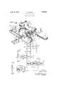
The single figure of the drawing is a diagrammatic view, partly in perspective, of the apparatus and circuit connections constituting the sending portion of a television system comprising a preferred embodimentof my invention. 7 a
The apparatus illustrated in the drawing comprises a storage reel 1, a take-up reel 2, a guiding device 3 for supporting a film 4:, and a'motor 5 for applying power to the take-up reel. The film is also given'motion longitudinally thereof by a rotating sprocket wheel 6, the teeth of which engage the marginal perforations in the film. The sprocket wheel 6 is mounted on a shaft 7 to which is affiXed-a spiral gear 8 that meshes with a spiral gear 9 mounted upon a countershaft 10 rotatably supported in suitable bearings 11.
A gear wheel 12 is also affixed to the countershaft. The gear wheel 12 meshes with a relatively long gear wheel 13 that is afiixed to the end of a main shaft 14 which extends parallel to the countershaft and is rotatably supported between aplurality of bearings 15.
Motive power is applied to the main shaft by a suitable constant-speed motor 16, preferably through a belt 17.
The guide 3, through which the film travels, is provided with a plurality of oppositely disposed transverse openings 20 and 21. Light from a source 22 is focused on the opening 20 to brightly illuminate a narrow longitudinal element of the film, as it travels past the openings. An image of the illuminated portion of the film is formed, by a lens 23 upon the face of a disc 25 that is mounted upon the main shaft 14 between the bearing 15 and the elongated gear wheel 13.
The disc is provided with a plurality of small square or sector-shape openings 26 disposed in a circular path adjacent to the perimeter thereof, the disc being so positioned that each of the openings is caused to successively traverse the film-element image where it, falls upon the face of the disc. The individual openings 26 are preferably formed in small discs 29 that overlie larger openings (not visible) in the disc itself, and are afiixed to the disc in any convenient way.
The spacing between the openings is made slightly greater than the length of the filmelement image in order that the said image may be traversed by only one opening at a time.
The countershaft 10 is slidably supported in the bearings 11 and an adjusting device 30 is provided whereby the shaft may be moved slightly in an axial direction. Such axial movement of the c'ountershaft, inasmuch as the said shaft is prevented from rotating by the engagement of the gears 12 and 13, causes the spiral gear 8 to rotate slightly in the one or the other direction, depending upon the direction in which the shaft is moved. The rotation of the spiral gear causes the filmengaging sprocket 6 to move the film slightly forward or back without interrupting the constant advance thereof.
A photo-electric cell 31, preferably of the alkaline-hydride type, is mounted rearwardly of the scanning disc 25 and is connected to the input terminals of an amplifier 32, prefera-bly of'the type comprising a plurality of thermionic'tubes and being capable of amplifying a wide range of frequencies. The purpose for which the amplifier is utilized will be hereinafter explained more fully in detail.
In order that the scanning disc shall be maintained in rotation at a constant angular velocity, the periphery thereof is so provided with a plurality of teeth 33 that the disc constitutes the rotor element of a synchronous motor. The stator element of the motor comprises a continuous winding of the type fully disclosed in my copending application, (Case 14,319) Serial No. 333,374, filed Jan. 18,
1929, and assigned to the Westinghouse Electric & Manufacturing Company.
In order that the drawing shall not be complicated, I have indicated the stator-portion of the disc-motor by a single magnetic element 34 having only two poles, it being understood that a much larger number of poles are present in the actual device. The statorwinding is energized from an amplifier 40 that, in turn, is supplied from a source 41 of oscillations.
Although I have spoken of the disc as being driven, as a synchronous motor, from the amplifier 40, it is not essential that all of the necessary torque shall be so supplied. The motors 5 and 16, therefore, are provided to take most of the load, leaving to the synchronous motor the task of maintaining constant the angular velocity of the disc.
In order to observe whether or not the disc is operating synchronously with the frequency from the source 41, a small glow tube 35, supplied from the amplifier 40, is so disposed with respect to the rotor-teeth that a stroboscopic effect is obtained thereby.
The constant-frequency source is also connected through one or more frequency multipliers 42, an intermediate amplifier 43 and a power amplifier 44 to a radiating structure preferably constituted by an antenna 45, a
tuning inductor 46 and a counterpoise or ground 47. i
The amplifier 32, associated with the photoelectric cell, energizes a modulator 48 which is connected to the intermediate amplifier just referred to and serves to impress modulating impulses thereon corresponding to variations in the photoelectric current.
The constant-frequency source 41 is connected, through a modulator 50 of any conventional type, to an oscillator 51. which energizes asecond structure, preferably comprising an antenna 52, a tuning inductor 53 and a counterpoise 54. The oscillator 51, in one successful commercial embodiment of my invention operates at a frequency of 3300 kilocycles.
The disc may be so geared to the film-advancing sprocket that the film is moved forward one frame during each revolution of the said disc, in which event each picture, or frame of the film is scanned by as many lines as there are openings in the disc. If it is desired to use a disc with a greater or less number of openings, the sixty-line scanning may still be obtained by altering the gearing.
I am not restricted to the use of sixty scanning lines per frame, however, it being obvious that the number of such lines is limited only by the speed of rotation of the disc. the total number of holes therethrough, and the gearing interposed between the disc and the film-driving sprocket.
Each scanning line, therefore, is representios ed by a series of fluctuations in the output current from the photocell, Which fluctuations are, through the instrumentality of the amplifier 32 and the modulator 4E8, impressed as modulations upon the carrier wave emitted from the antenna 45. At a receiving station, I preferably utilize a scanning device constituted by a rotatably mounted disc provided with a plurality of openings disposed in a spiral path. I also provide a suitable radio receiver tuned to the carrier frequency emitted from the antenna 45. The output current from the receiver is utilized to modulate the light given off by a glow tube of any well known type. The glow tube is supported adjacent to the rotatably mounted disc in the manner now well understood by those skilled in the art and is viewed from the opposite side thereof through a suitable lens system.
It is highly essential that the scanning disc at the transmitting end and all of the receiving discs shall be maintained in absolute rotational synchronism. This synchronism is attained by constructing the receiving disc in the form of a synchronous motor analogous to the transmitting disc, and by apply- I ing the same driving frequency to 1t as is applied to the transmitting disc. The driving frequency is obtained at the receiving sta tion by suitable radio receiving devices tuned to the 3300 kilocycle carrier emitted from the transmitting antenna 52, which carrier carries the said driving frequency as a modulation in the manner hereinbefore mentioned.
Each sending station is preferably equipped with a monitoring receiver not shown, comprising a rotating disc driven from the amplifier 40. If the image, as viewed in the monitoring receiver is out of frame, this indicates that the scanning of the separate pictures of the film does not begin at the same instant of time that the outermost hole of the spiral in the receiving disc is just starting to cross the viewing opening. When such is the case, the adjusting device 30 may be actuated to move the countershaft 10 slightly in an axial direction, thus causing the film to be moved either forward or backward a slight amount without disturbing either the motion of the scanning device or the constant forward movement of the film.
Irregularities in the angular velocity of the disc are prevented by a fly-wheel 60, loosely moiuited uppm the shaft 14 and driven therefrom through the medium of a plurality of friction elements 61 aifixed to the shaft at each side of the said wheel.
It will thus be apparent that I have by my invention provided a view-transmitting system that has many advantages. There is substantially no limit to the number of scanning lines per picture frame thatmay be utilized, although, by reason of certain limitations in photoelectric cells, as now manufactured, I prefer to limit the number of such lines to about sixty.
In addition to the value of my system in transmitting motion-picture films of the ordinary type, it will be of great value in the transmission of news-events, and the like,
since, by reason of recent improvements in the photographic art, films of any important event maybe developed and dried in an extremely short period after exposure.
When a negative film is transmitted by my improved system it can, by appropriate reversals in the connections of the receiving amplifier, be reproduced at the distant end as a positive picture on a screen, or a positive or negative film may be made at the receiving end directly from the output of the receiving scanning device.
Other advantages of my invention, as Well as numerous modifications thereof, will be apparent to. those skilled in the art to which it pertains. My invention, therefore, is not to be restricted to the specific apparatus illustrated and described herein, but is to be limited only by the prior art and by the spirit of the appended claims.
I claim as my invention: 1. In combination, a scanning device, means for actuating said scanning device at a substantially uniform rate and means. for
film, and energy-transferring means, coupling both of said actuating means, whereby the total load on said actuating means is proportionately distributed 3. In combination, a scanning device and a film, means for actuating said scanning device, independent means for actuating said film, and energy-transferring means coupling both of said actuating means, whereby the total load on said actuating means is proportionately distributed, said coupling mechanism comprising also a means for shifting the phase relationship of thefilm to the scanning device, whereby fine adjustments in the relative positions of the two might be made.
In testimony whereof, I have hereunto subscribed my name this 8th day of January,
FRANK CONRAD.
Priority Applications (1)
| Application Number | Priority Date | Filing Date | Title |
|---|---|---|---|
| US334413A US1853661A (en) | 1929-01-23 | 1929-01-23 | Television system |
Applications Claiming Priority (1)
| Application Number | Priority Date | Filing Date | Title |
|---|---|---|---|
| US334413A US1853661A (en) | 1929-01-23 | 1929-01-23 | Television system |
Publications (1)
| Publication Number | Publication Date |
|---|---|
| US1853661A true US1853661A (en) | 1932-04-12 |
Family
ID=23307093
Family Applications (1)
| Application Number | Title | Priority Date | Filing Date |
|---|---|---|---|
| US334413A Expired - Lifetime US1853661A (en) | 1929-01-23 | 1929-01-23 | Television system |
Country Status (1)
| Country | Link |
|---|---|
| US (1) | US1853661A (en) |
Cited By (1)
| Publication number | Priority date | Publication date | Assignee | Title |
|---|---|---|---|---|
| US2755163A (en) * | 1950-03-02 | 1956-07-17 | Nielsen A C Co | Recording device |
-
1929
- 1929-01-23 US US334413A patent/US1853661A/en not_active Expired - Lifetime
Cited By (1)
| Publication number | Priority date | Publication date | Assignee | Title |
|---|---|---|---|---|
| US2755163A (en) * | 1950-03-02 | 1956-07-17 | Nielsen A C Co | Recording device |
Similar Documents
| Publication | Publication Date | Title |
|---|---|---|
| US2420029A (en) | Printing telegraph transmission and reception system | |
| US1792264A (en) | Transmission of pictures | |
| US2354199A (en) | Method and means for television and other transmissions | |
| US1853661A (en) | Television system | |
| US2299738A (en) | Method of making and re-creating records | |
| US1891738A (en) | Talking movie | |
| US2000694A (en) | Television system | |
| US2409488A (en) | Facsimile communication system | |
| US2329624A (en) | Television recording apparatus | |
| US1867542A (en) | System of television | |
| US2382055A (en) | Remote control system | |
| US1690300A (en) | Transmission of pictures by electricity | |
| US2049384A (en) | System for television and sound | |
| US1884288A (en) | Facsimile transmission | |
| US1860502A (en) | Electric system for recording and reproducing sound | |
| US1885826A (en) | System of photography employing frequency modulation | |
| US1728986A (en) | Picture-transmission system | |
| US2128078A (en) | Television system | |
| US3848978A (en) | Analog information storage and retrieval system | |
| US1857451A (en) | Electric system for recording and reproducing sound | |
| US1874200A (en) | Electrooptical image producing system | |
| US1762470A (en) | Picture-transmission system | |
| US2140233A (en) | Telephotographic apparatus and the like | |
| US2164038A (en) | Facsimile transmission and reproduction | |
| US1775019A (en) | Synchronizing reproducing apparatus |