US1853625A - Fourdrinier machine - Google Patents
Fourdrinier machine Download PDFInfo
- Publication number
- US1853625A US1853625A US475724A US47572430A US1853625A US 1853625 A US1853625 A US 1853625A US 475724 A US475724 A US 475724A US 47572430 A US47572430 A US 47572430A US 1853625 A US1853625 A US 1853625A
- Authority
- US
- United States
- Prior art keywords
- sieve
- section
- breast roll
- roll
- wire
- Prior art date
- Legal status (The legal status is an assumption and is not a legal conclusion. Google has not performed a legal analysis and makes no representation as to the accuracy of the status listed.)
- Expired - Lifetime
Links
- 210000000481 breast Anatomy 0.000 description 48
- XLYOFNOQVPJJNP-UHFFFAOYSA-N water Substances O XLYOFNOQVPJJNP-UHFFFAOYSA-N 0.000 description 24
- 238000010276 construction Methods 0.000 description 6
- 239000000835 fiber Substances 0.000 description 4
- 230000007423 decrease Effects 0.000 description 2
- 241000838698 Togo Species 0.000 description 1
- 230000015572 biosynthetic process Effects 0.000 description 1
- 230000009172 bursting Effects 0.000 description 1
- 230000003247 decreasing effect Effects 0.000 description 1
- UKFTXGSXCYEAKH-UHFFFAOYSA-N dicyanomercury 1,3,5,7-tetrazatricyclo[3.3.1.13,7]decane Chemical group N#C[Hg]C#N.N#C[Hg]C#N.C1N2CN3CN1CN(C2)C3 UKFTXGSXCYEAKH-UHFFFAOYSA-N 0.000 description 1
- VJYFKVYYMZPMAB-UHFFFAOYSA-N ethoprophos Chemical compound CCCSP(=O)(OCC)SCCC VJYFKVYYMZPMAB-UHFFFAOYSA-N 0.000 description 1
- 238000005755 formation reaction Methods 0.000 description 1
- 230000005484 gravity Effects 0.000 description 1
- 230000004048 modification Effects 0.000 description 1
- 238000012986 modification Methods 0.000 description 1
- 230000000284 resting effect Effects 0.000 description 1
Images
Classifications
-
- D—TEXTILES; PAPER
- D21—PAPER-MAKING; PRODUCTION OF CELLULOSE
- D21F—PAPER-MAKING MACHINES; METHODS OF PRODUCING PAPER THEREON
- D21F9/00—Complete machines for making continuous webs of paper
- D21F9/02—Complete machines for making continuous webs of paper of the Fourdrinier type
Definitions
- the water acts as a conveyor for the pulp fibre. After the fiber is conveyed to the desired l0 place, it is necessary to get rid of the water. This is accomplished by making the stock water flow over a mechanically driven sieve or Wire.
- the meshes of this sieve are large enough to permit the water togo through but are too small to allow the pulpfibre to go through. The result is that as the water passes through the sieve, the fibres in the water settle on the sieve in the form of a web or sheet. This wire or sieve runs over a se-4 .U ries of rolls called tube or table rolls.
- the stock water is rushed by l o the head pressure over the inclined'sieve, this It is formed while therushing of the stock water causing thev fibre to form into a bulky sheet, very'important where a thick sheet and lig t weight is required.) This rushing does not continue all the way over the sieve table, but at a.' certain point along the table, as for instance lat a point one-third the distancefrom the breast this trouble and provide means whereby the making wire may be run on a steeper incline for a.
- portion of the wire is horizontal.
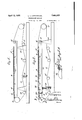
- F1 ure 1 is a diagrammatic elevation of a Fo rinier machine constructed accordlng to my invention
- Fi re 2 is a like view of Figure 1 showing an a justable form of the invention
- Figure 2a is a fragmentary elevation artl broken away of the forward end o the sleve table and a portion of the breast roll;
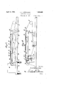
- Fi ure 3 is av hke view to Figures 1 and 2 but s owing a slightly different form of my A invention.
- Figure 4 is a diagrammatic elevation as in Figures 1 to 3 showing a still further modification of my invention.
- FIG. 1 I have illustrated diagrammaticall a Fourdrinier machine in which is provide the usual breast roll 10, the couch roll 11, the guide roll 12, tube rolls 13, the wire rolls 14 and the suction boxes 15.
- the web, sheet or wire netting 16 passes around the rolls 10 and 11 and over the rolls 12 and 13 and over and under the rolls 14 in the usual manner.
- This machine may be constructed in any suitable manner but as illustrated in Figure 1, the forward part of the wire 16 is upwardly inclined as at 17 from the breast roll for a certain distance and then is horizontall disposed from this point 18 to the guide ro 12; thus the front ortion of the wire is upwardly inclined and t e rear In this construction the inclination at 17 is fixed.
- the stock is caused to flow on an inclined making wire yat'that part of thel sieve table or wire from the breast roll to the point 18 and then the stock moves over a wire of P less inclination or a wire which is absolutely horizontal or slightly declined, thus preventing the stock water from dragging on the last part of its journey over the sieve table.
- FIG. 2 I show another form of my ⁇ invention which is preferable inasmuch as it permits the adjustment of the table as a whole as well as the separate adjustment of the first part of the wire. immediately following the breast roll.
- 19' designates the supporting beam for the rolls 13, these rolls being carried by
- the frame 20 includes a section 20a which is pivoted to the section 20 at 24 so that this section 20a may be shifted to any desired angular relation within certain limits to the section 20.
- the section 20a is held in this angularly adjusted position by means of the slotted braces 25 which are pivoted to the frame section 20a and extend down over the beam 19 and are held thereto by means of set screws 26.
- a support 27 is disposed between the axis of the breast roll 10 and the free end of the adjustable section 20a of the sieve table. It will be seen that in this case I have provided for the adjustment of the wholev sieve table so as to change its angularity and for an adjustment of the section 20a to increase or decrease its an larity with vreference to the section 20. y this means the section v20a may be independently shifted and changed without changing the inclination of the section 20 of the sieve table and that by raising ⁇ the jack 23 the main section 20 of the sieve that the breast roll is adjustable whilethe main portion of the sieve table is fixed. In
- 10 designates the breast roll, 11 the couch roll; 12 the guide roll, 13 the tube rolls, 14 the wire rolls, 15 the suction boxes, 16 the wire and 19 the beam.
- This beam is held in horizontal or in any other desired position by means of the usual supports 28.
- the main section of the sieve table 1s ⁇ designated 20 while the forward section of the sieve table is designated 20a and is hinged to the main section at 24 as previously described.
- This forward section 20a has its side frames connected to the axis of the breast roll 10. So far I have shown a construction which is the same as that shown in Figure 2. In the construction shown in Figure 3 the breast roll and the head box 29 are imacat .tion 20a of the sieve table.
- the member 27 constitutes a mere support for the free end of the sieve table. This. is not fastened to the sieve table, the freeend of the sieve table merely resting thereon. Normally the braces 25 and the supports 27 hold the weight of the sieve table, but when adjusted to the inclination of the table, the brace 25 is released by loosening theset screw 426 and under these circumstances, the vtable is supported by the support 27.
- one of the rolls 14 is to be what is known as a stretch roll adjustable so that the tension of the roll may be increased or decreased, thus permitting of a loosening on the tension of the wire 16 so as to permit of the section 20a being swung to different angles.
- the use of a rstretch roll is common in machines of this eneral character.l f
- A'Fourdrinier machine having a breast roll, a couchroll, a de roll, suction boxes,
- a breast roll In a Fourdrinier machine, a breast roll, a sieve table formed in two sections, and suction boxes at the rear end of the rear section, that section of the table adjacent the breast roll, being relatively short in comparison with the rear section and bein the rear sectionof the table an being operatively connected to the axis of the breast pivoted to roll, and means for raising or lowering the breast roll and the end of the section adjacent thereto, thus altering the inclination of the forward section 'of the sieve table.
- a breast roll and a sieve table formi-ng two sections, that j section adjacent the breast roll being relatively short being pivoted to the rear section at a point forward of the suction boxes and section of the sieve table adjacent the breast roll being relatively short and being pivoted to the rear section of the table at a distance from the forward suction box of4 the machine, and means for raising or lowering the forward end of the rear section of the table to thus change the inclination -of the forward section of the table relative to the rear section thereof.
- a breast roll In a Fourdrinier machine, a breast roll, a sieve table, and suction boxes coacting with the sieve table at a point remote from the breast roll, the table from the breast roll to a point between-the breast roll and the suction boxes being disposed at an upward and rearward inclination,'the remainder of the sieve table'extendin rearward to the suction boxes at laln angle to t e forward portion of the sieve ta e.
- a breast roll In a Fourdrinier machine, a breast roll, a sieve table, suction boxes disposed remote y'from the breast roll, the sieve table extending proximately one-third ofl the distance between the breast roll and the suction boxes and then extending rearward to the suction boxes at an angle to the forward portion of the sieve table.
- a breast roll a sieve table and suction boxes disposed remote from the breast roll, the sieve table being formed in two sections, the forward section, adjacent the breast roll, being pivoted to the rear section at a point between the suction boxes and the breast roll, this forward pivoted section being vertically adjustable, and means for adjusting the forward section into an angular relation to the rear section.
- a breast roll In a Fourdrinier machine, a breast roll, a sieve table, a member extending longitudinally beneath the sieve table, a roll supporting frame mounted upon said member and formed of a relatively short section adjacent the breast roll and a relatively long section extending rearward to the suction boxes, the
- the breast roll and a relatively' long section extending rearward to the suction boxes, the forwardv section of the table adjacent the breast roll being angularly adjustable with reference to the rear section of the table.
- a breast roll In a Fourdrinier machine, a breast roll, a sieve table formed to provide a relatively short section adjacent the breastroll and a relatively long section extending rearwardly therefrom, the two sections being hinged to each other, means for vertically shifting the forward end of the rear section of the table,
- a breast roll In a Fourdrinier machine, a breast roll, a sieve table formed to provide a relatively short section adjacent the breast roll and a relatively long section extending rearwardly therefrom, the two sections being hinged to each other, means for vertically shifting the forward end of the rear section of the table, and means for angularly adjusting the forward section of the table independently of the adjustment of the rear section including a l brace pivotally engaged with the forward section of the table.
- a breast roll In a Fourdriniermachine, a breast roll, a sieve table, the tableybeing formedin two sections, one of said lsections adjacent the breast rol l being relatively short, the other section extending rearward to the suction boxes being relatively long, the two sections ereof I hereunto aiix my.
Landscapes
- Paper (AREA)
Description
vApril l2, 1932. l, LAPEYROUSI; v FOURDRIFNIER MACHINE' Filed Aug.. 16. 195o 2 sheets-sheet 1 April 12, 1932.
| L, LAPEYRoUsE FOURDRINIEB MACHINE v Filed Aug. 16. 1930 2 Sheets-Sheet 2 Patented Apr. 12, 1932 UNITED' STATES VPA'rlazNT ori-ICE LAWRENCE L. LAPEYROUSE, F MOBILE, ALABAMA FOURDRINIER MACHINE application med August 1e, iaso. semi No. 475,724.
of paper on a Fourdrinier machine, the pulp,
is mixed with a quantity of water. The water acts as a conveyor for the pulp fibre. After the fiber is conveyed to the desired l0 place, it is necessary to get rid of the water. This is accomplished by making the stock water flow over a mechanically driven sieve or Wire. The meshes of this sieve are large enough to permit the water togo through but are too small to allow the pulpfibre to go through. The result is that as the water passes through the sieve, the fibres in the water settle on the sieve in the form of a web or sheet. This wire or sieve runs over a se-4 .U ries of rolls called tube or table rolls. These rolls which hold the sieve level are inthe form of a table and play a veryl important part in making the water go through the sieve as the water is pulled away from the sieve by 2" the slight suction or vacuum ei'ect caused by the surface of the roll pulling away (in its rotation) from contact with the sieve. On a Fourdrinier machine a sheet of paper is formed by the stock water acting as a conveyor for the fibre flowing o-ver a sieve or wire. The greatest part of the water drops or Hows through the sieve by gravity. The remaining part of the water must be forced out through the suction boxes by means of powerful vacuum pumps. The stock water does not How after it reaches the suction boxes. It is, therefore, an accepted fact lthat 4 a sheet of paper is formed befo-re i-t reaches the suction part. o sieve is traveling over the table rolls and not while it is traveling over the suction part, because when itreaches the suction part, the sheet or web, although still wet, is far too thick or heavy to allow the water to flow 5 Different formations of a sheet of paper are effected by changing the flow of thelstock water. In making board or calipered paper, the general practice is to run the sieve table on an incline. The stock water is rushed by l o the head pressure over the inclined'sieve, this It is formed while therushing of the stock water causing thev fibre to form into a bulky sheet, very'important where a thick sheet and lig t weight is required.) This rushing does not continue all the way over the sieve table, but at a.' certain point along the table, as for instance lat a point one-third the distancefrom the breast this trouble and provide means whereby the making wire may be run on a steeper incline for a. certain distance over that part of the sieve table adjacent the breast roll and then carried rearward for the remaining part of the distance either in a horizontal plane, an upwardly inclined plane, or at a declination, thus eliminating the diiiiculty experienced from dragging In this construction, the stock water will he rushed on the inclined portion of the wire but at the point where the head pressure is spent, the Wire will travel either on-a less inclined table or level table or a table which is downwardly inclined to thus prevent the stock water from dragging. In making the Fourdrinier board or calipered paper it is necessary thatsaid board or paper shall have a certain thickness'to comply with rail-road shipping requirements.
On the other hand, the paper box manufacturers vwant their board to weigh as'little as possible and at the same time have a high bursting strength. We have thus the obviouslydiiic'ult problem of combining little weight, bulk and strength all in the same sheet, and therefore it is an object of this invention to provide means whereby this light weight, bulk and strength may be secured. l
c "portion of the wire is horizontal.
Other objects will appear in the course of the following description.
My invention 1s lllustrated 1n the accompanying drawings wherein: 'n
F1 ure 1 is a diagrammatic elevation of a Fo rinier machine constructed accordlng to my invention;
Fi re 2 is a like view of Figure 1 showing an a justable form of the invention,
Figure 2a is a fragmentary elevation artl broken away of the forward end o the sleve table and a portion of the breast roll;
Fi ure 3 is av hke view toFigures 1 and 2 but s owing a slightly different form of my A invention; and
Figure 4 is a diagrammatic elevation as in Figures 1 to 3 showing a still further modification of my invention.
In Figure 1 I have illustrated diagrammaticall a Fourdrinier machine in which is provide the usual breast roll 10, the couch roll 11, the guide roll 12, tube rolls 13, the wire rolls 14 and the suction boxes 15. The web, sheet or wire netting 16 passes around the rolls 10 and 11 and over the rolls 12 and 13 and over and under the rolls 14 in the usual manner. This machine may be constructed in any suitable manner but as illustrated in Figure 1, the forward part of the wire 16 is upwardly inclined as at 17 from the breast roll for a certain distance and then is horizontall disposed from this point 18 to the guide ro 12; thus the front ortion of the wire is upwardly inclined and t e rear In this construction the inclination at 17 is fixed. I am aware of the fact that, as before stated,
in this type of paper making machine it has been proposed to have the upper flight of the wire extend at an inclination from the breast roll to the guide roll that is, to a point just in advance of the suction boxes 15 but under these circumstances the stock water is rushed by the head pressure for a part of the distance over the sieve table and then this stock water drags back tending to disrupt the sheet which is formed on the first part of the wire over the sieve table.
In the construction shown in Figure 1,
however, the stock is caused to flow on an inclined making wire yat'that part of thel sieve table or wire from the breast roll to the point 18 and then the stock moves over a wire of P less inclination or a wire which is absolutely horizontal or slightly declined, thus preventing the stock water from dragging on the last part of its journey over the sieve table.
In Figure 2 I show another form of my `invention which is preferable inasmuch as it permits the adjustment of the table as a whole as well as the separate adjustment of the first part of the wire. immediately following the breast roll. In the drawings, 19'designates the supporting beam for the rolls 13, these rolls being carried by The frame 20 includes a section 20a which is pivoted to the section 20 at 24 so that this section 20a may be shifted to any desired angular relation within certain limits to the section 20. The section 20a is held in this angularly adjusted position by means of the slotted braces 25 which are pivoted to the frame section 20a and extend down over the beam 19 and are held thereto by means of set screws 26. Thus, it will be seen that by loosening the set screws 26 and raising or lowering the free ends of the beam 19 that the inclination of the forward section 20a may be varied with reference to the rear section 20.
j A support 27 is disposed between the axis of the breast roll 10 and the free end of the adjustable section 20a of the sieve table. It will be seen that in this case I have provided for the adjustment of the wholev sieve table so as to change its angularity and for an adjustment of the section 20a to increase or decrease its an larity with vreference to the section 20. y this means the section v20a may be independently shifted and changed without changing the inclination of the section 20 of the sieve table and that by raising `the jack 23 the main section 20 of the sieve that the breast roll is adjustable whilethe main portion of the sieve table is fixed. In
these figures, 10 designates the breast roll, 11 the couch roll; 12 the guide roll, 13 the tube rolls, 14 the wire rolls, 15 the suction boxes, 16 the wire and 19 the beam. This beam is held in horizontal or in any other desired position by means of the usual suports 28. The main section of the sieve table 1s` designated 20 while the forward section of the sieve table is designated 20a and is hinged to the main section at 24 as previously described. This forward section 20a has its side frames connected to the axis of the breast roll 10. So far I have shown a construction which is the same as that shown in Figure 2. In the construction shown in Figure 3 the breast roll and the head box 29 are imacat .tion 20a of the sieve table.
In Figure 4 I haveshown a form of myr invention which is very much like that shown in Figure 2 and which therefore bears the same numerals except as hereinafter stated. In this form2 the beam 19 is pivoted at 22 as before descr bed. The forward end of the sieve table is vertically adjustable by means of the brace or braces 25, and the beam 19 Ais tiltable by means of the slotted member 32 extending down over a vertical support .33, it being engageable at anyA desired position Vwith this vertical support by means of a set screw 34 passing through a slot within the member 32.
It will be seen in all forms of my invention I have illustrated a sieve table which 1s inclined to a certain degree at a relatively steep angle for a certain distance from the breast roll but which is horizontal or declined or inclined at a lesser degree for the remainder of the table, thus enabling the stock water to be rushed up a relatively 25 .steep incline for a partof the distance over the sieve table and -on a less incline or a level or on a slight decline, thereby preventing the stock water from dragging ,on the latter part of its ourney over the sieve table.
Due to excessive dragging on the Fourdrinier machines now in use, a limited` amount of inclination of the sieve table is used. The more inclined this table is, the more dragging will take place. With my improvement it is'possible to use a much greater inclination on that part of the sieve table adjacent the breast roll without experiencing any difficulty in dragging.
While I have illustrated four separate forms of my invention, I have illustrated ,these diagrammatically and I do not wish to be limited to all details of construction. or
arrangement of parts which areshown, as obviously many changes might be made without departing from the spirit of theA invention as defined in appended claims.
It will be understood that in Figures 2y and 4, the member 27 constitutes a mere support for the free end of the sieve table. This. is not fastened to the sieve table, the freeend of the sieve table merely resting thereon. Normally the braces 25 and the supports 27 hold the weight of the sieve table, but when adjusted to the inclination of the table, the brace 25 is released by loosening theset screw 426 and under these circumstances, the vtable is supported by the support 27.
It is also to be understood that one of the rolls 14 is to be what is known as a stretch roll adjustable so that the tension of the roll may be increased or decreased, thus permitting of a loosening on the tension of the wire 16 so as to permit of the section 20a being swung to different angles. The use of a rstretch roll is common in machines of this eneral character.l f
I c aim:
1.` A'Fourdrinier machine having a breast roll, a couchroll, a de roll, suction boxes,
i a series of tube rois1 disposed between thel suction boxes and the breast roll, a sieve table -upon whichI the tube rolls are mounted, and
a wire passing over the breast roll, the tube rolls, the suction boxes, the couch rolls, and back to the breast roll that portion of the sieve table from the breast roll rearward for a certain distance less than the distance between jthe breast roll and the suction boxes being upwardly inclined, the remainder of the wire to the suction boxes being at an angle to the forward portion of the wire.
2. In a Fourdrinier machine, a breast roll, a sieve table formed in two sections, and suction boxes at the rear end of the rear section, that section of the table adjacent the breast roll, being relatively short in comparison with the rear section and bein the rear sectionof the table an being operatively connected to the axis of the breast pivoted to roll, and means for raising or lowering the breast roll and the end of the section adjacent thereto, thus altering the inclination of the forward section 'of the sieve table.
3.- In a Fourdrinier machine, a breast roll and a sieve table formi-ng two sections, that j section adjacent the breast roll being relatively short being pivoted to the rear section at a point forward of the suction boxes and section of the sieve table adjacent the breast roll being relatively short and being pivoted to the rear section of the table at a distance from the forward suction box of4 the machine, and means for raising or lowering the forward end of the rear section of the table to thus change the inclination -of the forward section of the table relative to the rear section thereof.
5. In a Fourdrinier machine, a breast roll, a sieve table, and suction boxes coacting with the sieve table at a point remote from the breast roll, the table from the breast roll to a point between-the breast roll and the suction boxes being disposed at an upward and rearward inclination,'the remainder of the sieve table'extendin rearward to the suction boxes at laln angle to t e forward portion of the sieve ta e.
6. In a Fourdrinier machine, a breast roll, a sieve table, suction boxes disposed remote y'from the breast roll, the sieve table extending proximately one-third ofl the distance between the breast roll and the suction boxes and then extending rearward to the suction boxes at an angle to the forward portion of the sieve table.
7. In a Fourdrinier machine, a breast roll, a sieve table and suction boxes disposed remote from the breast roll, the sieve table being formed in two sections, the forward section, adjacent the breast roll, being pivoted to the rear section at a point between the suction boxes and the breast roll, this forward pivoted section being vertically adjustable, and means for adjusting the forward section into an angular relation to the rear section.
8. In a Fourdrinier machine, a breast roll, a sieve table, a member extending longitudinally beneath the sieve table, a roll supporting frame mounted upon said member and formed of a relatively short section adjacent the breast roll and a relatively long section extending rearward to the suction boxes, the
bein hinged to each other a beam su port the lgear section of the brast table, t e belalirgl being pivoted at its rear end and vertically adjustable at its forward end, and means for angularly adjusting the forward section of the sieve table independently of the adjustment of the rear section including a brace `pivotally engaged with the forward section LAWRENCE L. LAPEYRoUsE.
the breast roll and a relatively' long section extending rearward to the suction boxes, the forwardv section of the table adjacent the breast roll being angularly adjustable with reference to the rear section of the table.
,10. In a Fourdrinier machine, a breast roll, a sieve table formed to provide a relatively short section adjacent the breastroll and a relatively long section extending rearwardly therefrom, the two sections being hinged to each other, means for vertically shifting the forward end of the rear section of the table,
and means for angularly adjusting the forward section of the table independently of the adjustment of the rear section.
11. In a Fourdrinier machine, a breast roll, a sieve table formed to provide a relatively short section adjacent the breast roll and a relatively long section extending rearwardly therefrom, the two sections being hinged to each other, means for vertically shifting the forward end of the rear section of the table, and means for angularly adjusting the forward section of the table independently of the adjustment of the rear section including a l brace pivotally engaged with the forward section of the table. l'
12. In a Fourdriniermachine, a breast roll, a sieve table, the tableybeing formedin two sections, one of said lsections adjacent the breast rol l being relatively short, the other section extending rearward to the suction boxes being relatively long, the two sections ereof I hereunto aiix my.
Priority Applications (1)
| Application Number | Priority Date | Filing Date | Title |
|---|---|---|---|
| US475724A US1853625A (en) | 1930-08-16 | 1930-08-16 | Fourdrinier machine |
Applications Claiming Priority (1)
| Application Number | Priority Date | Filing Date | Title |
|---|---|---|---|
| US475724A US1853625A (en) | 1930-08-16 | 1930-08-16 | Fourdrinier machine |
Publications (1)
| Publication Number | Publication Date |
|---|---|
| US1853625A true US1853625A (en) | 1932-04-12 |
Family
ID=23888843
Family Applications (1)
| Application Number | Title | Priority Date | Filing Date |
|---|---|---|---|
| US475724A Expired - Lifetime US1853625A (en) | 1930-08-16 | 1930-08-16 | Fourdrinier machine |
Country Status (1)
| Country | Link |
|---|---|
| US (1) | US1853625A (en) |
Cited By (2)
| Publication number | Priority date | Publication date | Assignee | Title |
|---|---|---|---|---|
| US2890149A (en) * | 1949-10-31 | 1959-06-09 | J M Voith G M B H Maschinenfab | Method and apparatus for making paper |
| US3230138A (en) * | 1962-06-06 | 1966-01-18 | Berges Andre Charles | Pulp dewatering apparatus |
-
1930
- 1930-08-16 US US475724A patent/US1853625A/en not_active Expired - Lifetime
Cited By (2)
| Publication number | Priority date | Publication date | Assignee | Title |
|---|---|---|---|---|
| US2890149A (en) * | 1949-10-31 | 1959-06-09 | J M Voith G M B H Maschinenfab | Method and apparatus for making paper |
| US3230138A (en) * | 1962-06-06 | 1966-01-18 | Berges Andre Charles | Pulp dewatering apparatus |
Similar Documents
| Publication | Publication Date | Title |
|---|---|---|
| NO154811B (en) | Projectile HEAD. | |
| US1853625A (en) | Fourdrinier machine | |
| US3876499A (en) | Web forming between two wires having a curved path of travel | |
| US3677305A (en) | Loom having interconnected warp let-off and cloth take-up means at back of loom | |
| US2060808A (en) | Hydraulic inlet for paper making machines | |
| US2127698A (en) | Paper making machine | |
| US2003753A (en) | Vertically adjustable tables for fourdrinier machines | |
| US1668333A (en) | High-draft speed frame for drawing, twisting, and winding textile materials | |
| US2527802A (en) | Corn picker | |
| US1906355A (en) | Paper-making machine | |
| US3135650A (en) | Flow system for paper formers | |
| US1998095A (en) | Paper making apparatus | |
| US3215594A (en) | Paper forming apparatus | |
| US1273549A (en) | Hydroaeroplane. | |
| US1466120A (en) | Paper-making machine | |
| US2104052A (en) | Apparatus for making saturated, sized, filled, or coated paper or fiberboard | |
| US1525335A (en) | Disk harrow | |
| US1697737A (en) | Textile-material drawing | |
| US1086555A (en) | Photographic plate and holder. | |
| US1536293A (en) | Brace construction for headers | |
| US1275826A (en) | Fourdriner machine. | |
| US1477020A (en) | Machine | |
| US1982349A (en) | Fourdrinier paper machine | |
| US1766733A (en) | Loom picker-rod spindle support | |
| US1549288A (en) | Spinning frame |