US1853624A - Heat control valve - Google Patents
Heat control valve Download PDFInfo
- Publication number
- US1853624A US1853624A US239374A US23937427A US1853624A US 1853624 A US1853624 A US 1853624A US 239374 A US239374 A US 239374A US 23937427 A US23937427 A US 23937427A US 1853624 A US1853624 A US 1853624A
- Authority
- US
- United States
- Prior art keywords
- ports
- exhaust
- jacket
- control valve
- heat control
- Prior art date
- Legal status (The legal status is an assumption and is not a legal conclusion. Google has not performed a legal analysis and makes no representation as to the accuracy of the status listed.)
- Expired - Lifetime
Links
- 239000007789 gas Substances 0.000 description 6
- 238000005192 partition Methods 0.000 description 4
- 238000002485 combustion reaction Methods 0.000 description 2
- 239000000446 fuel Substances 0.000 description 2
- 238000010438 heat treatment Methods 0.000 description 2
- 230000008016 vaporization Effects 0.000 description 2
- 238000010276 construction Methods 0.000 description 1
- 239000000284 extract Substances 0.000 description 1
- 230000008014 freezing Effects 0.000 description 1
- 238000007710 freezing Methods 0.000 description 1
- 238000012423 maintenance Methods 0.000 description 1
- 238000009834 vaporization Methods 0.000 description 1
Images

Classifications
-
- F—MECHANICAL ENGINEERING; LIGHTING; HEATING; WEAPONS; BLASTING
- F02—COMBUSTION ENGINES; HOT-GAS OR COMBUSTION-PRODUCT ENGINE PLANTS
- F02M—SUPPLYING COMBUSTION ENGINES IN GENERAL WITH COMBUSTIBLE MIXTURES OR CONSTITUENTS THEREOF
- F02M31/00—Apparatus for thermally treating combustion-air, fuel, or fuel-air mixture
- F02M31/02—Apparatus for thermally treating combustion-air, fuel, or fuel-air mixture for heating
- F02M31/04—Apparatus for thermally treating combustion-air, fuel, or fuel-air mixture for heating combustion-air or fuel-air mixture
- F02M31/06—Apparatus for thermally treating combustion-air, fuel, or fuel-air mixture for heating combustion-air or fuel-air mixture by hot gases, e.g. by mixing cold and hot air
- F02M31/08—Apparatus for thermally treating combustion-air, fuel, or fuel-air mixture for heating combustion-air or fuel-air mixture by hot gases, e.g. by mixing cold and hot air the gases being exhaust gases
- F02M31/081—Manual switching of the fluids directed to the heat exchange surfaces
-
- Y—GENERAL TAGGING OF NEW TECHNOLOGICAL DEVELOPMENTS; GENERAL TAGGING OF CROSS-SECTIONAL TECHNOLOGIES SPANNING OVER SEVERAL SECTIONS OF THE IPC; TECHNICAL SUBJECTS COVERED BY FORMER USPC CROSS-REFERENCE ART COLLECTIONS [XRACs] AND DIGESTS
- Y02—TECHNOLOGIES OR APPLICATIONS FOR MITIGATION OR ADAPTATION AGAINST CLIMATE CHANGE
- Y02T—CLIMATE CHANGE MITIGATION TECHNOLOGIES RELATED TO TRANSPORTATION
- Y02T10/00—Road transport of goods or passengers
- Y02T10/10—Internal combustion engine [ICE] based vehicles
- Y02T10/12—Improving ICE efficiencies
Definitions
- This invention relates to an improved form of exhaust gas bypass heating jacket for the intake manifold of an internal combustion engine.
- the vaporizing of fuel in the intake manifold at times extracts so much heat as to cause freezing of condensate on the surface of an unheated intake manifold, this frost vbeing evidence that the proper vaporization of the fuel requires a large amount of heat.
- a xed supply of heat is undesirable for the reason that a suilicient supply for one set of conditions, such as air temperature, power output, and speed, is entirely unsuited for variations in these conditions so that a readily adjustable supp-ly of heat to a jacketed manifold is a highly desirable feature which is incorporated in the present invention, which comprises a bypass jacket surrounding the uptake of the intake manifold together with a valve controlling inlet and outlet ports in the jacket and at the same time acting to bypass the exhaust gases through the jacket when the ports are open.
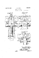
- Figure l is a fragmentary elevation lof exhaust and intake manifolds incorporating the features of this invention.
- Figure 2 is a central vertical section of Figure 1 with parts in elevation. j
- Figure 3 is a section on the line III- III of Figure 2.
- Figure 4 is asection on the line l of Figure 2.
- Figure 5 is afragmentary elevation of a modified forml of manual controlfor the bylpass valve.
- Y l As shown on the drawings: i Y
- An exhaust manifold 10 is provided rwith a flanged side opening 11 to which is bolted afbypassjacket. 12 integral with and surrounding the uptake 13 from ⁇ a carbureter connection ⁇ 14having 'a throttle valve l5.; the intake manifold also having side branches 16 extendingbeyondthe walls of the jacket.
- the jacket 12 isprovided with a central partitionj 17 extendingv nearlyy to the bottoml thereof, ports 18 and 19 opening intorthe exhaust manifold on either side of the partition so that t'he bypass path of the exhaust gases rcomprises entry at one of the ports 18 or 19, 'thence downwardly onrone side of the partition, around the lower'edge thereof,and upwardly on the other side, exiting back into the exhaust manifold through the other ofthe ports 18 or 19.
- vAn outstandingplate 22 is also carried by the disk, this ⁇ .plate 4serving to substantially block the ⁇ ex- ⁇ haust- ⁇ manifold betweenjthe bypass ⁇ por-ts 'when the ports are f ully open, thus causing a nearly complete? diversion of the Vexhaust gases through the jacket.
- a lever 23 is pinned to the'outer 'end "of .the valve shaft to partially rotate the saine, and in Figures fl andr2 this lever Ais connected to a stiff Vwire 24 incased ina flexible Ybut not extensible tube 25. ⁇ clamped adjacent .the leverby a bracket 26.'
- the other endqf the tube is attached to a guide 27 for a push and pull rod 28, the guide being mounted in a control panel or dash 29 convenient to the 95 operator.
- the combination of the wire and incasing tube is commonly termed a Bowden wire.
- the push and pull rod 28 is provided with a number of grooves 30 and a spring detent 31 is mounted in the guide 27 to en- .i100
- the modified control of Figure 5 utilizes a hand lever 32 pivoted on one of the studs 33 holding the jacket 12 against the exhaust pipe flange ll, this hand lever 32 having a link 34 extending to the valve shaft lever 23..
- a spring detent 35 in the pivoted end of the hand lever30 rides over a serrated surface within a fixed quadrant 36.
- an opening in the exhaust manifold a jacket for the intake manifold extending to and covering said opening, inlet andeutlet ports opening into the exhaust manifold, a segmentally aperturedVV disk rotatably mounted on the exhaust side of. said ports, an outstanding plate secured to said disk and adapted to substantiallyclose Ythe exhaust manifold between the ports when said disk is turned to open said ports, manually adjustable means adapted to rotate said disk, and means adapted to yieldingly maintain an adjustment when once set.
Landscapes
- Engineering & Computer Science (AREA)
- Chemical & Material Sciences (AREA)
- Combustion & Propulsion (AREA)
- Mechanical Engineering (AREA)
- General Engineering & Computer Science (AREA)
- Exhaust Silencers (AREA)
Description
April 12, 193.2. c. H. KIRBY i HEAT CONTROL VALVE Filed Dec. 1 2, 1927 2`Shees-Sheet l w .KL
April 12, 1932. c. H. KIRBY HEAT CONTROL VALVE Filed Dec. l2, 1927 2 Sheets-Sheet 2 Patented Apr. 12, 1932 UNITED STATES CHARLES H. HIRBY, or FLINT, MICHIGAN, AssIGNoItfTof MARVEL QANBUILETER CoM- PANY, or FLINT,1v11CHICAN, A CORPORATION or ILLINOIS Y HEAT CONTROL vALvE Application led December 12d, 1927. Serial No. 239,374.
This invention relates to an improved form of exhaust gas bypass heating jacket for the intake manifold of an internal combustion engine.
It is an ob-ject'of this invention to provide an improved structure of the type described comprising an adjustable heat control for bypassing varying amounts of exhaust gases through a jacket on the intake manifold in accordance with the varying conditions of operation of the engine. The vaporizing of fuel in the intake manifold at times extracts so much heat as to cause freezing of condensate on the surface of an unheated intake manifold, this frost vbeing evidence that the proper vaporization of the fuel requires a large amount of heat. However, a xed supply of heat is undesirable for the reason that a suilicient supply for one set of conditions, such as air temperature, power output, and speed, is entirely unsuited for variations in these conditions so that a readily adjustable supp-ly of heat to a jacketed manifold is a highly desirable feature which is incorporated in the present invention, which comprises a bypass jacket surrounding the uptake of the intake manifold together with a valve controlling inlet and outlet ports in the jacket and at the same time acting to bypass the exhaust gases through the jacket when the ports are open. j
It is another object of this invention to provide an improved and simplified intake manifold heater than can becheaply manufactured and installed.
Other and further important objects of this invention will be apparent from the dis-y closures in the specification and the accompanying drawings.
This invention (in a preferred form) is illustrated in the drawings and hereinafter more fully described.
On the drawings:
Figure l is a fragmentary elevation lof exhaust and intake manifolds incorporating the features of this invention.
Figure 2 is a central vertical section of Figure 1 with parts in elevation. j
Figure 3 is a section on the line III- III of Figure 2.
Figure 4 is asection on the line l of Figure 2.
Figure 5 is afragmentary elevation of a modified forml of manual controlfor the bylpass valve. Y l As shown on the drawings: i Y
An exhaust manifold 10 is provided rwith a flanged side opening 11 to which is bolted afbypassjacket. 12 integral with and surrounding the uptake 13 from `a carbureter connection `14having 'a throttle valve l5.; the intake manifold also having side branches 16 extendingbeyondthe walls of the jacket. The jacket 12 isprovided with a central partitionj 17 extendingv nearlyy to the bottoml thereof, ports 18 and 19 opening intorthe exhaust manifold on either side of the partition so that t'he bypass path of the exhaust gases rcomprises entry at one of the ports 18 or 19, 'thence downwardly onrone side of the partition, around the lower'edge thereof,and upwardly on the other side, exiting back into the exhaust manifold through the other ofthe ports 18 or 19. A segmentally apertured disk20 is carried by a shaft 21, this disk being adapted to simultaneously Cover and un= coverthe two ports 18 and 19; vAn outstandingplate 22 isalso carried by the disk, this `.plate 4serving to substantially block the `ex-` haust-` manifold betweenjthe bypass `por-ts 'when the ports are f ully open, thus causing a nearly complete? diversion of the Vexhaust gases through the jacket.
both'forms a lever 23 is pinned to the'outer 'end "of .the valve shaft to partially rotate the saine, and in Figures fl andr2 this lever Ais connected to a stiff Vwire 24 incased ina flexible Ybut not extensible tube 25.` clamped adjacent .the leverby a bracket 26.' The other endqf the tube is attached to a guide 27 for a push and pull rod 28, the guide being mounted in a control panel or dash 29 convenient to the 95 operator. The combination of the wire and incasing tube is commonly termed a Bowden wire. The push and pull rod 28 is provided with a number of grooves 30 and a spring detent 31 is mounted in the guide 27 to en- .i100
gage in one of the grooves to hold the rod in its adjusted position.
The modified control of Figure 5 utilizes a hand lever 32 pivoted on one of the studs 33 holding the jacket 12 against the exhaust pipe flange ll, this hand lever 32 having a link 34 extending to the valve shaft lever 23.. In order to assure maintenance of the adjustment a spring detent 35 in the pivoted end of the hand lever30 rides over a serrated surface within a fixed quadrant 36.
It will thus be seen that I have produced an improved and simplified manually controlled exhaust gas bypass heating jacket for intake manifolds.
I am aware that many changes may be made, and numerous details of construction may be varied through a wide range without departing from the principles-of this invention, and I therefore do not purpose limiting the patent granted hereon, otherwise than necessitated by the prior art.
I claim as my invention:
1. In combination with the exhaust and intake manifolds of an internal combustion engine, an opening in the exhaust manifold, a jacket for-the intakemanifold extending to and covering said opening, a central partition in said jacket extending nearly the full llength thereof, inlet and outlet ports on either side of said partition and opening into the exhaust manifold, a segmentally apertured disk rotatably mounted on the exhaust side of said ports, an outstanding plate secured to said disk and adapted to substantially close the exhaust manifold between the ports when said disk is turned to yopen said ports, manually adjustable means adapted to rotate said disk, and means adapted to yieldingly maintain an adjustment when once set.
2. In combination with the exhaust and intake manifolds of an internalcombustion engine, an opening in the exhaust manifold, a jacket for the intake manifold extending to and covering said opening, inlet andeutlet ports opening into the exhaust manifold, a segmentally aperturedVV disk rotatably mounted on the exhaust side of. said ports, an outstanding plate secured to said disk and adapted to substantiallyclose Ythe exhaust manifold between the ports when said disk is turned to open said ports, manually adjustable means adapted to rotate said disk, and means adapted to yieldingly maintain an adjustment when once set.
In testimony whereof I have hereunto subscribed my name.
CHARLES I-I. KIRBY.
Priority Applications (1)
| Application Number | Priority Date | Filing Date | Title |
|---|---|---|---|
| US239374A US1853624A (en) | 1927-12-12 | 1927-12-12 | Heat control valve |
Applications Claiming Priority (1)
| Application Number | Priority Date | Filing Date | Title |
|---|---|---|---|
| US239374A US1853624A (en) | 1927-12-12 | 1927-12-12 | Heat control valve |
Publications (1)
| Publication Number | Publication Date |
|---|---|
| US1853624A true US1853624A (en) | 1932-04-12 |
Family
ID=22901889
Family Applications (1)
| Application Number | Title | Priority Date | Filing Date |
|---|---|---|---|
| US239374A Expired - Lifetime US1853624A (en) | 1927-12-12 | 1927-12-12 | Heat control valve |
Country Status (1)
| Country | Link |
|---|---|
| US (1) | US1853624A (en) |
-
1927
- 1927-12-12 US US239374A patent/US1853624A/en not_active Expired - Lifetime
Similar Documents
| Publication | Publication Date | Title |
|---|---|---|
| US1761960A (en) | Butterfly-valve exhaust pipe | |
| US1448008A (en) | Heat control of mixture for internal-combustion engines | |
| US1853624A (en) | Heat control valve | |
| US1811829A (en) | A corpora | |
| US4030457A (en) | Vapor carburetor | |
| US1684599A (en) | Motor-vehicle heater | |
| US1867457A (en) | Charge forming device for internal combustion engines | |
| US1325286A (en) | Gas-engine gas-saver and carbon-decomposer | |
| US1792560A (en) | Crank-case-ventilating system for internal-combustion engines | |
| US1434445A (en) | Fuel-heating attachment for engines | |
| US2733698A (en) | voigt | |
| US1732103A (en) | Automobile heater | |
| US1815623A (en) | Crankcase ventilation | |
| US1680373A (en) | Intake manifold and heating-medium control for internal-combustion engines | |
| US1359168A (en) | Controlling mechanism for exhaust-gases of internal-combustion engines | |
| US1222548A (en) | Kerosene-vaporizer. | |
| US1800426A (en) | Heat-control apparatus for intake gases of internal-combustion engines | |
| US1540144A (en) | Charge-heating control for internal-combustion engines | |
| US1643957A (en) | Charge-heating control for internal-combustion engines | |
| US1322415A (en) | Auxiliary air-intake | |
| US1448682A (en) | Hydrocarbon motor | |
| US1800318A (en) | Method of and means for heating automobiles | |
| US1371189A (en) | Hot-air-controlling device for air-intake of carbureters | |
| US1487234A (en) | Carburetor | |
| US1655170A (en) | Intake heater |